Loading ...
Loading ...
Loading ...
PROCEDURE 4--ELECTRICAL CONNECTIONS
NOTE: See B for electrical connection of size 071.
A. Sizes 018 Through 070
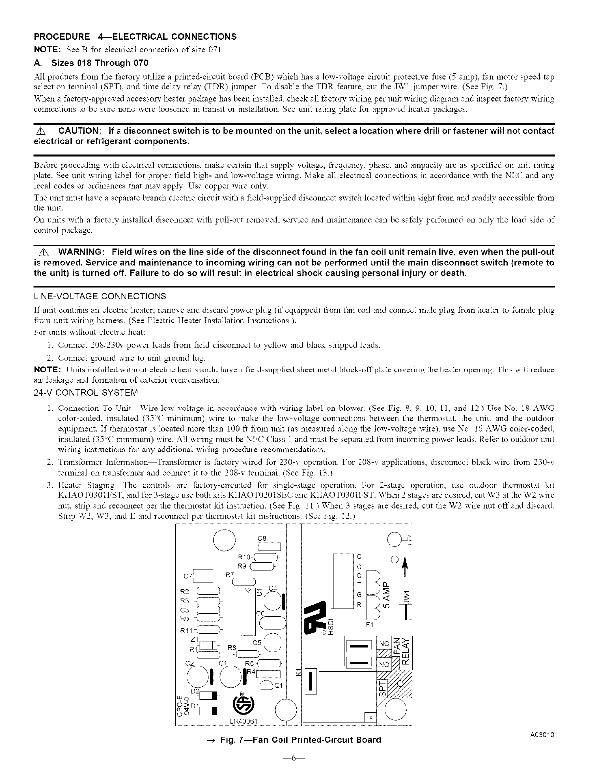
All products fi'om the factory utilize a printed-circuit board (PCB) which has a low-voltage circuit protective fuse (5 amp), fan motor speed tap
selection terminal (SPT), and time delay relay (TDR) jumper. To disable the TDR feature, cut the JWl jumper wire. (See Fig. 7.)
When a _actory-approved accessory heater package has been installed, check all factory wiring per unit wiring diagram and inspect factory wiring
connections to be sure none were loosened in transit or installation. See unit rating plate for approved heater packages.
Z_ CAUTION: If adisconnect switch is to be mounted on the unit, select a location where drill or fastener will not contact
electrical or refrigerant components.
Before proceeding with electrical connections, make certain that supply voltage, fi'equency, phase, and ampacity are as specified on unit rating
plate. See unit wiring label for proper field high- and low-voltage wiring. Make all electrical connections in accordance with the NEC and any
local codes or ordinances that may apply. Use copper wire only.
The unit nmst have a separate branch electric circuit with a field-supplied disconnect switch located within sight from and readily accessible fi'om
the unit.
On units with a factory installed disconnect with pull-out removed, service and maintenance can be safely performed on only the load side of
control package.
Z_ WARNING: Field wires on the line side of the disconnect found in the fan coil unit remain live, even when the pull-out
is removed. Service and maintenance to incoming wiring can not be performed until the main disconnect switch (remote to
the unit) is turned off. Failure to do so will result in electrical shock causing personal injury or death.
LINE-VOLTAGE CONNECTIONS
If unit contains an electric heater, remove and discard power plug (if equipped) from fan coil and connect male plug from heater to female plug
fi'om unit wiring harness. (See Electric Heater Installation Instructions.).
For units without electric heat:
i. Connect 208/230v power leads fi'om field disconnect to yellow and black stripped leads.
2. Connect ground wire to unit ground lug.
NOTE: Units installed without electric heat should have a field-supplied sheet metal bloek-offplate covering the heater opening. This will reduce
air leakage and formation of exterior condensation.
24-V CONTROL SYSTEM
i. Connection To Unit Wire low voltage in accordance with wiring label on blower. (See Fig. 8, 9, 10, ll, and 12.) Use No. 18 AWG
color-coded, insulated (35°(; minimum) wire to make the low-voltage connections between the thermostat, the unit, and the outdoor
equipment. If thermostat is located more than 100 ft from unit (as measured along the low-voltage wire), use No. 16 AWG color-coded,
insulated (35°C minimum) wire. All wiring nmst be NEC (?lass 1 and must be separated fi'om incoming power leads. Refer to outdoor unit
wiring instructions for any additional wiring procedure recommendations.
2. Transformer Inlbrmation Transformer is _actory wired for 230-v operation. For 208-v applications, disconnect black wire fi'om 230-v
terminal on transformer and connect it to the 208-v terminal. (See Fig. 13.)
3. Heater Staging The controls are factory-circuited for single-stage operation. For 2-stage operation, use outdoor thermostat kit
KHAOT0301FST, and for 3-stage use both kits KHAOT0201SEC and KHAOT0301FST. When 2stages are desired, cut W3 at the W2 wire
nut, strip and reconnect per the thermostat kit instruction. (See Fig. 11.) When 3 stages are desired, cut the W2 wire nut off and discard.
Strip W2, W3, and E and reconnect per thermostat kit instructions. (See Fig. 12.)
C8
-_ Fig. 7--Fan Coil Printed-Circuit Board A03010
6
Loading ...
Loading ...
Loading ...