Loading ...
Loading ...
Loading ...
i. Thestandard90secoffdelay(Factorysetting)at100percentairflow.
2. No delay option used for servicing unit or when a thermostat is utilized to perlbrm delay functions.
3. A 30 sec on delay with no airflow/90 sec off delay at 100 percent airflow profile is used when it is desirable to allow system coils time
to heat-up/cool-down in conjunction with the airflow.
4. ENH, enhanced selection, provides a 30 sec on delay with no airflow/plus 150 sec at 70 percent airflow/no off delay for added comfort.
This profile will minimize cold blow in heat pump operation and could enhance system efficiency.
F. CONTINUOUS FAN -- Select desired fan speed when thermostat is set on continuous fan
i. LO speed factory setting, 50% cooling mode airflow
2. MED speed move connector to MED, 65% cooling mode airflow
3. HI speed move connector of HI, 100% cooling mode airflow. (See Fig. 21, F as indicated.)
G. LOW-VOLTAGE CIRCUIT FUSING AND REFERENCE
The low-voltage circuit is fused by a board mounted 5-amp automotive fuse placed in series with the transformer SEC2 and the R circuit. The C
circuit of the transformer is referenced to chassis ground through a printed circuit run at SEC 1 connected to metal standoff marked with ground
symbol.
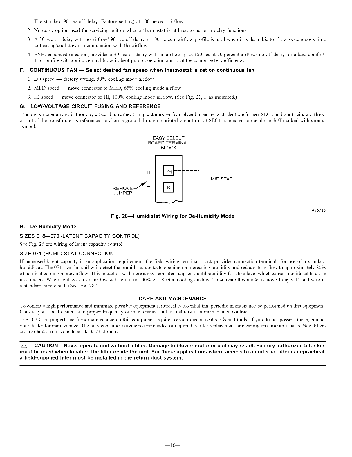
EASY SELECT
BOARD TERMINAL
BLOCK
J1
REMOVEJ
JUMPER
D ..... ] HUMIDISTAT
El- ..... J
Fig. 28--Humidistat Wiring for De-Humidify Mode
A95316
H. De-Humidify Mode
SIZES 018--070 (LATENT CAPACITY CONTROL)
See Fig. 26 for wiring of latent capacity control.
SIZE 071 (HUMIDISTAT CONNECTION)
If increased latent capacity is an application requirement, the field wiring terminal block provides connection terminals for use of a standard
humidistat. The 071 size fan coil will detect the humidistat contacts opening on increasing humidity and reduce its airflow to approximately 80%
of nominal cooling mode airflow. This reduction will increase system latent capacity until humidity falls to a level which causes humidistat to close
its contacts. When contacts close, airflow will returu to 100% of selected cooling airflow. To activate this mode, remove Jnmper J1 and wire in
a standard humidistat. (See Fig. 28.)
CARE AND MAINTENANCE
To continue high performance and minimize possible equipment failure, it is essential that periodic maintenance be performed on this equipment.
Consult your local dealer as to proper frequency of maintenance and availability of a maintenance contract.
The ability to properly perform maintenance on this equipment requires certain mechanical skills and tools. If you do not possess these, contact
your dealer for maintenance. The only consumer service recommended or required is filter replacement or cleaning on a monthly basis. New filters
are available from your local dealer distributor.
z_ CAUTION: Never operate unit without a filter. Damage to blower motor or coil may result. Factory authorized filter kits
must be used when locating the filter inside the unit. For those applications where access to an internal filter is impractical,
a field-supplied filter must be installed in the return duct system.
16
Loading ...
Loading ...
Loading ...