
V1.00.002
08-12-2020

LAUNCH
I
www.x431.com +86 755 8455 7891
Copyright Information
Copyright © 2020 by LAUNCH TECH CO., LTD. All rights reserved. No part of
this publication may be reproduced, stored in a retrieval system, or transmitted
in any form or by any means, electronic, mechanical, photocopying and
recording or otherwise, without the prior written permission of LAUNCH. The
information contained herein is designed only for the use of this unit. LAUNCH
is not responsible for any use of this information as applied to other units.
Statement: LAUNCH owns the complete intellectual property rights for the software
used by this product. For any reverse engineering or cracking actions against the
software, LAUNCH will block the use of this product and reserve the right to pursue
their legal liabilities.
Trademark Information
LAUNCH is a registered trademark of LAUNCH TECH CO., LTD. (also
called LAUNCH for short) in China and other countries. All other LAUNCH
trademarks, service marks, domain names, logos, and company names
referred to in this manual are either trademarks, registered trademarks,
service marks, domain names, logos, company names of or are otherwise
the property of LAUNCH or its affiliates. In countries where any of the
LAUNCH trademarks, service marks, domain names, logos and company
names are not registered, LAUNCH claims other rights associated with
unregistered trademarks, service marks, domain names, logos, and company
names. Other products or company names referred to in this manual may
be trademarks of their respective owners. You may not use any trademark,
service mark, domain name, logo, or company name of LAUNCH or any third
party without permission from the owner of the applicable trademark, service
mark, domain name, logo, or company name. You may contact LAUNCH by
visiting the website at www.cnlaunch.com, or writing to LAUNCH TECH. CO.,
LTD., Launch Industrial Park, North of Wuhe Avenue, Banxuegang, Bantian,
Longgang, Shenzhen, Guangdong, P.R.China, to request written permission to
use Materials on this manual for purposes or for all other questions relating to
this manual.
SAFETY PRECAUTIONS AND WARNINGS
To prevent personal injury or damage to vehicles and/or the test equipment,
please read this user’s manual rst carefully and observe the following safety
precautions at a minimum whenever working on a vehicle:
• There are no user serviceable parts. Have the device serviced by a qualied
repair person using only identical replacement parts. This will ensure that
the safety of the device is maintained. Disassembling the device will void

LAUNCH
II
www.x431.com +86 755 8455 7891
the warranty right.
• CAUTION: This tool contains an internal Lithium Polymer battery. The
battery can burst or explode, releasing hazardous chemicals. To reduce
the risk of re or burns, do not disassemble, crush, pierce or dispose of the
battery in re or water.
• This product is not a toy. Do not allow children to play with or near this item.
• Do not expose the device to rain or wet conditions.
• Do not place the device on any unstable surface.
• Never leave the device unattended during charging process. The device
must be placed on a non-ammable surface during charging.
• Handle the device with care. If the device is dropped, check for breakage
and any other conditions that my aect its operation.
• Do not operate the tool in explosive atmospheres, such as in the presence
of ammable liquids, gases, or heavy dust.
• Keep the tool dry, clean, free from oil, water or grease. Use a mild detergent
on a clean cloth to clean the outside of the device when necessary.
• People with pacemakers should consult their physician(s) before use.
Electromagnetic elds in close proximity to heart pacemaker could cause
pacemaker interference or pacemaker failure.
• Always perform automotive testing in a safe environment.
• Do not attempt to operate or observe the tool while driving a vehicle.
Operating or observing the tool will cause driver distraction and could cause
a fatal accident.
• Wear safety eye protection that meets ANSI standards.
• Keep clothing, hair, hands, tools, test equipment, etc. away from all moving
or hot engine parts.
• Operate the vehicle in a well-ventilated work area: Exhaust gases are
poisonous.
• Put blocks in front of the drive wheels and never leave the vehicle
unattended while running tests.
• Use extreme caution when working around the ignition coil, distributor
cap, ignition wires and spark plugs. These components create hazardous
voltages when the engine is running.
• Put the transmission in P (for A/T) or N (for M/T) and make sure the parking
brake is engaged.
• Keep a fire extinguisher suitable for gasoline/chemical/ electrical fires

LAUNCH
III
www.x431.com +86 755 8455 7891
nearby.
• Don’t connect or disconnect any test equipment while the ignition is on or
the engine is running.
FCC Statement
This device complies with Part 15 of the FCC Rules. Operation is subject to
the following two conditions:
(1) This device may not cause harmful interference, and
(2) This device must accept any interference received, including interference
that may cause undesired operation.

LAUNCH
IV
www.x431.com +86 755 8455 7891
Table of Contents
1. Introduction .................................................................................................1
2. General Information-About OBDII/EOBD .................................................3
2.1 On-Board Diagnostics (OBD) I ...................................................................3
2.2 On-Board Diagnostics (OBD) II ..................................................................3
2.3 Diagnostic Trouble Codes (DTCs) ..............................................................5
2.4 Location of the Data Link Connector (DLC)................................................6
2.5 OBD II Terminology ....................................................................................7
2.6 OBD II Monitors ..........................................................................................9
2.6.1 Continuous Monitors..........................................................................9
2.6.2 Non-Continuous Monitors ................................................................11
2.6.3 OBD II Reference Table ...................................................................14
2.7 DTCs and MIL Status ...............................................................................16
3. Product Descriptions ...............................................................................18
3.1 General Controls ......................................................................................18
3.2 Specications ...........................................................................................20
3.3 Accessories ..............................................................................................20
4. Initial Use...................................................................................................22
4.1 Charging & Turning On/O .......................................................................22
4.1.1 Charging ..........................................................................................22
4.1.2 Turning On/O .................................................................................22
4.2 Main Menu ................................................................................................23
4.2.1 Function modules ............................................................................23
4.2.2 Icons & Symbols ..............................................................................23
4.3 Settings ....................................................................................................24
5. TPMS Operations .....................................................................................26
5.1 Check Sensor ...........................................................................................28
5.2 Program Sensor .......................................................................................31
5.2.1 Auto create ......................................................................................31
5.2.2 Manual input ....................................................................................33

LAUNCH
V
www.x431.com +86 755 8455 7891
5.2.3 Copy ID by activation.......................................................................36
5.2.4 Program multi-sensor .....................................................................38
5.3 TPMS Service ...........................................................................................39
5.3.1 Relearn procedure ...........................................................................39
5.3.2 Part number lookup .........................................................................40
6. OBD Diagnosing ......................................................................................41
6.1 Connection ...............................................................................................41
6.2 Start OBD Diagnostics..............................................................................42
7. Help ...........................................................................................................52
7.1 DLC Location Information .........................................................................52
7.2 Tool Information ........................................................................................52
7.3 Library Version..........................................................................................53
7.4 Software Update Guide ............................................................................53
8. Register & Update ....................................................................................54
9. FAQ ............................................................................................................57

LAUNCH
1
www.x431.com +86 755 8455 7891
1. Introduction
This TPMS activation & diagnostic tool is specially developed by LAUNCH,
which enables users to trigger TPMS sensor, program TPMS sensor, perform
the relearning procedure and check sensor part number. Additionally, it also
supports all 10 modes of OBD II test for a complete diagnosis.
With built-in help menus and code denitions, diagnosing and repairing that
dreaded Check Engine Light is now easier than ever!
This tool provides the following functions:
TPMS:
• Trigger the TPMS sensor
• Program the TPMS sensor
• Provide TPMS relearning procedures and sensor OE number lookup
OBD diagnosis:
• Read dynamic data streams and MIL
• Read readiness status
• Freeze frame data
• Read DTCs
• Clear DTCs
• O
2
sensor test
• On-board monitor test
• Read vehicle information
Moreover, it can be updated via the memory card to keep synchronized with
the latest available software version.
Note: This tool may automacally reset while being disturbed by strong stac
electricity. THIS IS A NORMAL REACTION.
This tool is specially designed to work with all OBD II compliant vehicles,
including Controller Area Network (CAN). It is required by EPA that all 1996
and newer vehicles (cars and light trucks) sold in the United States must be
OBD II compliant and this includes all American, Asian and European vehicles.
A small number of 1994 and 1995 model year gasoline vehicles are OBD II
compliant. To verify if a 1994 or 1995 vehicle is OBD II compliant, check the
following:
LAUNCH
2
www.x431.com +86 755 8455 7891
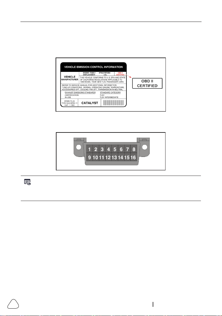
1.
Vehicle Emissions Control Information (VECI) Label
. It is located
under the hood or by the radiator of most vehicles. If the vehicle is OBD II
compliant, the label will designate “OBD II Certied”.
2. Government regulations mandate that all OBD II compliant vehicles
must
have a “common” 16-pin
Data Link Connector (DLC)
.
Note: Some 1994 and 1995 vehicles have 16-pin connectors but are not OBD II
compliant. Only those vehicles with a Vehicle Emissions Control Label stang “OBD
II Cered” are OBD II compliant.

LAUNCH
3
www.x431.com +86 755 8455 7891
2. General Information-About OBDII/EOBD
2.1 On-Board Diagnostics (OBD) I
Note: With the exception of some 1994 and 1995 vehicles, most vehicles
from 1982 to 1995 are equipped with some type of first generation On-Board
Diagnoscs.
Beginning in 1988, California’s Air Resources Board (CARB), and later the
Environmental Protection Agency (EPA) required vehicle manufacturers to
include a self-diagnostic program in their on-board computers. The program
would be capable of identifying emissions-related faults in a system. The rst
generation of Onboard Diagnostics came to be known as OBD I.
OBD I is a set of self-testing and diagnostic instructions programmed into
the vehicle’s onboard computer. The programs are specifically designed to
detect failures in the sensors, actuators, switches and wiring of the various
vehicle emissions-related systems. If the computer detects a failure in any of
these components or systems, it lights an indicator on the dashboard to alert
the driver. The indicator lights only when an emissions-related problem is
detected.
The computer also assigns a numeric code for each specic problem that it
detects, and stores these codes in its memory for later retrieval. These codes
can be retrieved from the computer’s memory with the use of a “Code Reader”
or a “Diagnostic Tool.”
2.2 On-Board Diagnostics (OBD) II
As technology evolved and the desire to improve the On-Board Diagnostic
system increased, a new generation of On-Board Diagnostic system was
developed. This second generation of On-Board Diagnostic regulations is
called “OBD II”.
In addition to performing all the functions of the OBD I System, the OBD II
System has been enhanced with new Diagnostic Programs. These programs
closely monitor the functions of various emissions-related components and
systems (as well as other systems) and make this information readily available
(with the proper equipment) to the technician for evaluation.
The California Air Resources Board (CARB) conducted studies on OBD I
equipped vehicles. The information that was gathered from these studies

LAUNCH
4
www.x431.com +86 755 8455 7891
showed the following:
• A large number of vehicles had deteriorating or degraded emissions-related
components. These components were causing an increase in emissions.
• Because OBD I systems only detect failed components, the degraded
components were not setting codes.
• Some emissions problems related to degraded components only occur
when the vehicle is being driven under a load. The emission checks
being conducted at the time were not performed under simulated driving
conditions. As a result, a significant number of vehicles with degraded
components were passing Emissions Tests.
• Codes, code denitions, diagnostic connectors, communication protocols
and emissions terminology were different for each manufacturer. This
caused confusion for the technicians working on dierent make and model
vehicles.
To address the problems made evident by this study, CARB and the EPA
passed new laws and standardization requirements. These laws required
that vehicle manufacturers to equip their new vehicles with devices capable
of meeting all of the new emissions standards and regulations. It was also
decided that an enhanced on-board diagnostic system, capable of addressing
all of these problems, was needed. This new system is known as “On-
Board Diagnostics Generation Two (OBD II/OBD 2).” The primary objective
of the OBD II system is to comply with the latest regulations and emissions
standards established by CARB and the EPA.
The Main Objectives of the OBD II System are:
• To detect degraded and/or failed emissions-related components or systems
that could cause tailpipe emissions to exceed by 1.5 times the Federal Test
Procedure (FTP) standard.
• To expand emissions-related system monitoring. This includes a set of
computer run diagnostics called Monitors. Monitors perform diagnostics
and testing to verify that all emissions-related components and/or systems
are operating correctly and within the manufacturer’s specications.
• To use a standardized Diagnostic Link Connector (DLC) in all vehicles.
(Before OBD II, DLCs were of dierent shapes and sizes.)
• To standardize the code numbers, code denitions and language used to
describe faults. (Before OBD II, each vehicle manufacturer used their own
code numbers, code denitions and language to describe the same faults.)
• To expand the operation of the Malfunction Indicator Lamp (MIL).

LAUNCH
5
www.x431.com +86 755 8455 7891
• To standardize communication procedures and protocols between the
diagnostic equipment (Diagnostic Tools, Code Readers, etc.) and the
vehicle’s on-board computer.
2.3 Diagnostic Trouble Codes (DTCs)
OBD II Diagnostic Trouble Codes are codes that are stored by the on-board
computer diagnostic system in response to a problem found in the vehicle.
These codes identify a particular problem area and are intended to provide
you with a guide as to where a fault might be occurring within a vehicle.
DO
NOT
replace parts based only on DTCs without rst consulting the vehicle’s
service manual for proper testing procedures for that particular system, circuit
or component.
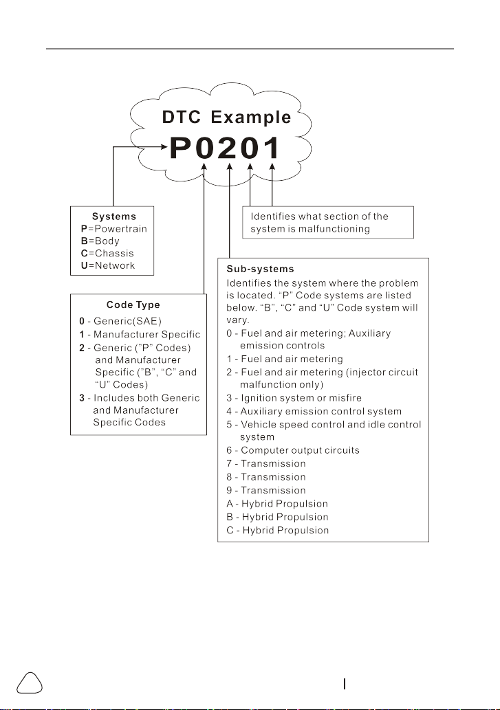
OBD II Diagnostic Trouble Codes consist of a ve-digit alphanumeric code.
• The 1st character is a
letter
(B, C, P or U). It identies the “main system”
where the fault occurred (Body, Chassis, Powertrain, or Network).
• The 2nd character is a
numeric digit
(0 thru 3). It identies the “type” of
code (Generic or Manufacturer-Specic).
Generic DTCs are codes that are used by all vehicle manufacturers. The
standards for generic DTCs, as well as their definitions, are set by the Society of
Automotive Engineers (SAE).
Manufacturer-Specific DTCs are codes that are controlled by the vehicle
manufacturers. The Federal Government does not require vehicle
manufacturers to go beyond the standardized generic DTCs in order to comply
with the new OBD II emissions standards. However, manufacturers are free
to expand beyond the standardized codes to make their systems easier to
diagnose.
• The 3rd character is a letter or a
numeric digit
(0 thru 9, A thru F). It
identies the specic system or sub-system where the problem is located.
• The 4th and 5th characters are
letters
or
numeric digits
(0 thru 9, A thru
F). They identify the section of the system that is malfunctioning.
LAUNCH
6
www.x431.com +86 755 8455 7891
P0201 - Injector circuit malfunction, Cylinder 1
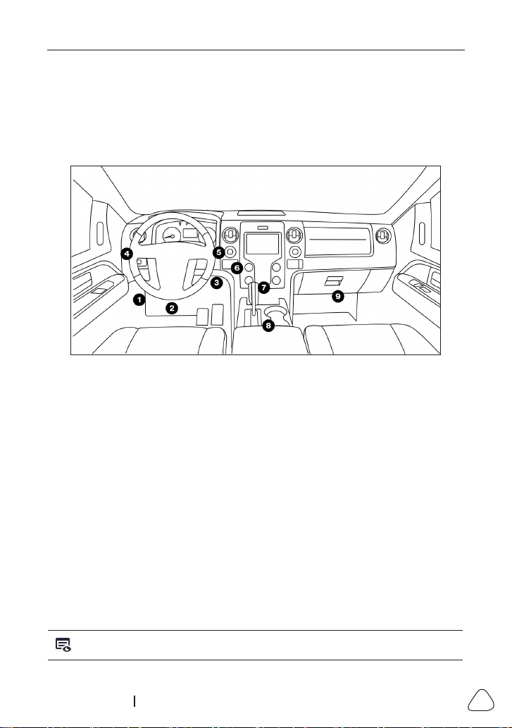
2.4 Location of the Data Link Connector (DLC)
The DLC (Data Link Connector or Diagnostic Link Connector) is the
standardized 16-cavity connector where diagnostic code readers interface with
the vehicle’s on-board computer. The DLC is usually located 12 inches from
the center of the instrument panel (dash), under or around the driver’s side for
LAUNCH
7
www.x431.com +86 755 8455 7891
most vehicles. If Data Link Connector is not located under dashboard, a label
should be there telling location. For some Asian and European vehicles, the
DLC is located behind the ashtray and the ashtray must be removed to access
the connector. If the DLC cannot be found, refer to the vehicle’s service
manual for the location.
2.5 OBD II Terminology
The following terms and their definitions are related to OBD II systems.
Read and reference this list as needed to aid in the understanding of OBD II
systems.
Powertrain Control Module (PCM)
-- The PCM is the OBD II accepted term
for the vehicle’s “on-board computer.” In addition to controlling the engine
management and emissions systems, the PCM also participates in controlling
the powertrain (transmission) operation. Most PCMs also have the ability to
communicate with other computers on the vehicle (ABS, ride control, body,
etc.).
Monitors
-- Monitors are “diagnostic routines” programmed into the PCM. The
PCM utilizes these programs to run diagnostic tests, and to monitor operation
of the vehicle’s emissions-related components or systems to ensure they
are operating correctly and within the vehicle’s manufacturer specifications.
Currently, up to fifteen Monitors are used in OBD II systems. Additional
Monitors will be added as the OBD II system is further developed.
Note: Not all vehicles support all een Monitors.

LAUNCH
8
www.x431.com +86 755 8455 7891
Enabling Criteria
-- Also termed Enabling Conditions. They are the vehicle-
specific events or conditions that must occur within the engine before the
various monitors will set, or run. Some monitors require the vehicle to follow
a prescribed “drive cycle” routine as part of the enabling criteria. Drive cycles
vary among vehicles and for each monitor in any particular vehicle. Please
refer to the vehicle’s factory service manual for specic enabling procedures.
Trip
- A Trip for a particular Monitor requires that the vehicle is being driven
in such a way that all the required “Enabling Criteria” for the Monitor to run
and complete its diagnostic testing are met. The “Trip Drive Cycle” for a
particular Monitor begins when the ignition key is turned “On.” It is successfully
completed when all the “Enabling Criteria” for the Monitor to run and complete
its diagnostic testing are met by the time the ignition key is turned “O.” Since
each of the fteen monitors is designed to run diagnostics and testing on a
dierent part of the engine or emissions system, the “Trip Drive Cycle” needed
for each individual Monitor to run and complete varies.
OBD II Drive Cycle
-- A specific mode of vehicle operation that provides
conditions required to set all the readiness monitors applicable to the vehicle
to the “ready” condition. The purpose of completing an OBD II drive cycle is
to force the vehicle to run its onboard diagnostics. Some form of a drive cycle
needs to be performed after DTCs have been erased from the PCM’s memory
or after the battery has been disconnected. Running through a vehicle’s
complete drive cycle will “set” the readiness monitors so that future faults can
be detected. Drive cycles vary depending on the vehicle and the monitor that
needs to be reset. For vehicle specic drive cycle, consult the service manual.
Note: Do not confuse a “Trip” Drive Cycle with an OBD II Drive Cycle. A “Trip”
Drive Cycle provides the “Enabling Criteria” for one specic Monitor to run and
complete its diagnostic testing. An OBD II Drive Cycle must meet the “Enabling
Criteria” for all Monitors on a particular vehicle to run and complete their
diagnosc tesng.
Warm-up Cycle
- Vehicle operation after an engine o period where engine
temperature rises at least 40°F (22°C) from its temperature before starting,
and reaches at least 160°F (70°C). The PCM uses warm-up cycles as a
counter to automatically erase a specific code and related data from its
memory. When no faults related to the original problem are detected within a
specied number of warm-up cycles, the code is erased automatically.
Fuel Trim (FT)
- Feedback adjustments to the base fuel schedule. Short-term

LAUNCH
9
www.x431.com +86 755 8455 7891
fuel trim refers to dynamic or instantaneous adjustments. Long-term fuel trim
refers to much more gradual adjustments to the fuel calibration schedule than
short-term trim adjustments. These long-term adjustments compensate for
vehicle dierences and gradual changes that occur over time.
2.6 OBD II Monitors
An important part of a vehicle’s OBD II system is the Readiness Monitors,
which are indicators used to nd out if all of the emissions components have
been evaluated by the OBD II system. They are running periodic tests on
specic systems and components to ensure that they are performing within
allowable limits.
Monitor operation is either “Continuous” or “Non-Continuous,” depending on
the specic monitor.
2.6.1 Continuous Monitors
Some of the vehicle components or systems are continuously tested by the
vehicle’s OBD II system, while others are tested only under specic vehicle
operating conditions. The continuously monitored components listed below are
always ready:
1. Misre Monitor
This Monitor continuously checks for engine misres. A misre occurs when
the air-fuel mixture in the cylinder does not ignite. The misre Monitor uses
changes in crankshaft speed to sense an engine misfire. When a cylinder
misres, it no longer contributes to the speed of the engine, and engine speed
decreases each time the affected cylinder(s) misfire. The misfire Monitor
is designed to sense engine speed fluctuations and determine from which
cylinder(s) the misre is coming, as well as how bad the misre is.
There are three types of engine misres, Types 1, 2, and 3.
• Type 1 and Type 3 misres are two-trip monitor faults. If a fault is sensed
on the rst trip, the computer temporarily saves the fault in its memory as
a Pending Code. The MIL is not commanded on at this time. If the fault is
found again on the second trip, under similar conditions of engine speed,
load and temperature, the computer commands the MIL “On,” and the code
is saved in its long term memory.
• Type 2 misres are the most severe type of misre. When a Type 2 misre
is sensed on the rst trip, the computer commands the MIL to light when
the misre is sensed. If the computer determines that a Type 2 misre is

LAUNCH
10
www.x431.com +86 755 8455 7891
severe, and may cause catalytic converter damage, it commands the MIL
to “flash” once per second as soon as the misfire is sensed. When the
misre is no longer present, the MIL reverts to steady “On” condition.
The Misfire Monitor is supported by both “spark ignition” vehicles and
“compression ignition” vehicles.
2. Fuel System Monitor
This Monitor uses a Fuel System Correction program, called Fuel Trim, inside
the on-board computer. Fuel Trim is a set of positive and negative values that
represent adding or subtracting fuel from the engine. This program is used
to correct for a lean (too much air/not enough fuel) or rich (too much fuel/not
enough air) air-fuel mixture. The program is designed to add or subtract fuel,
as needed, up to a certain percent. If the correction needed is too large and
exceeds the time and percent allowed by the program, a fault is indicated by
the computer.
The Fuel System Monitor is supported by both “spark ignition” vehicles and
“compression ignition” vehicles. The Fuel System Monitor may be a “One-Trip”
or “Two-Trip” Monitor, depending on the severity of the problem.
3. Comprehensive Components Monitor (CCM)
This Monitor continuously checks all inputs and outputs from sensors,
actuators, switches and other devices that provide a signal to the computer.
The Monitor checks for shorts, opens, out of range value, functionality and
“rationality* (
See Note
).”
Raonality: Each input signal is compared against all other inputs and against
informaon in the computer’s memory to see if it makes sense under the current
operang condions.
Example: The signal from the throttle position sensor indicates the vehicle is
in a wide-open throttle condition, but the vehicle is really at idle, and the idle
condion is conrmed by the signals from all other sensors. Based on the input
data, the computer determines that the signal from the throle posion sensor
is not raonal (does not make sense when compared to the other inputs). In this
case, the signal would fail the raonality test.
The CCM is supported by both “spark ignition” vehicles and “compression
ignition” vehicles. The CCM may be either a “One-Trip” or a “Two-Trip”
Monitor, depending on the component.

LAUNCH
11
www.x431.com +86 755 8455 7891
2.6.2 Non-Continuous Monitors
“Non-continuous” Monitors perform and complete their testing once per trip.
The “non-continuous” Monitors are:
1. O
2
Sensor Monitor
The Oxygen Sensor monitors how much oxygen is in the vehicle’s exhaust. It
generates a varying voltage of up to one volt, based on how much oxygen is
in the exhaust gas, and sends the signal to the computer. The computer uses
this signal to make corrections to the air/fuel mixture. If the exhaust gas has a
large amount of oxygen (a lean air/fuel mixture), the oxygen sensor generates
a “low” voltage signal. If the exhaust gas has very little oxygen (a rich mixture
condition), the oxygen sensor generates a “high” voltage signal. A 450mV
signal indicates the most efficient, and least polluting, air/fuel ratio of 14.7
parts of air to one part of fuel.
The oxygen sensor must reach a temperature of at least 600-650°F, and the
engine must reach normal operating temperature, for the computer to enter
into closed-loop operation.
The oxygen sensor only functions when the computer is in closed-loop. A
properly operating oxygen sensor reacts quickly to any change in oxygen
content in the exhaust stream. A faulty oxygen sensor reacts slowly, or its
voltage signal is weak or missing.
The Oxygen Sensor Monitor is supported by “spark ignition” vehicles only.
The Oxygen Sensor Monitor is a “Two-Trip” monitor. If a fault is found on the
rst trip, the computer temporarily saves the fault in its memory as a Pending
Code. The computer does not command the MIL on at this time. If the fault is
sensed again on the second trip, the computer commands the MIL “On,” and
saves the code in its long-term memory.
2. O
2
Sensor Heater Monitor
The Oxygen Sensor Heater Monitor tests the operation of the oxygen sensor’s
heater. There are two modes of operation on a computer-controlled vehicle:
“open-loop” and “closed-loop.” The vehicle operates in open-loop when the
engine is cold, before it reaches normal operating temperature. The vehicle
also goes to open-loop mode at other times, such as heavy load and full
throttle conditions. When the vehicle is running in open-loop, the oxygen
sensor signal is ignored by the computer for air/fuel mixture corrections.
Engine efficiency during open-loop operation is very low, and results in the
production of more vehicle emissions.
Closed-loop operation is the best condition for both vehicle emissions and

LAUNCH
12
www.x431.com +86 755 8455 7891
vehicle operation. When the vehicle is operating in closed-loop, the computer
uses the oxygen sensor signal for air/fuel mixture corrections.
In order for the computer to enter closed-loop operation, the oxygen sensor
must reach a temperature of at least 600°F. The oxygen sensor heater helps
the oxygen sensor reach and maintain its minimum operating temperature
(600°F) more quickly, to bring the vehicle into closed-loop operation as soon
as possible.
The Oxygen Sensor Heater Monitor is supported by “spark ignition” vehicles
only. The Oxygen Sensor Heater Monitor is a “Two-Trip” Monitor. If a fault is
found on the rst trip, the computer temporarily saves the fault in its memory
as a Pending Code. The computer does not command the MIL on at this time.
If the fault is sensed again on the second trip, the computer commands the
MIL “On,” and saves the code in its long-term memory.
3. Catalyst Monitor
The catalytic converter is a device that is installed downstream of the exhaust
manifold. It helps to oxidize (burn) the unburned fuel (hydrocarbons) and
partially burned fuel (carbon monoxide) left over from the combustion process.
To accomplish this, heat and catalyst materials inside the converter react
with the exhaust gases to burn the remaining fuel. Some materials inside
the catalytic converter also have the ability to store oxygen, and release it
as needed to oxidize hydrocarbons and carbon monoxide. In the process,
it reduces vehicle emissions by converting the polluting gases into carbon
dioxide and water.
The computer checks the eciency of the catalytic converter by monitoring the
oxygen sensors used by the system. One sensor is located before (upstream
of) the converter; the other is located after (downstream of) the converter. If
the catalytic converter loses its ability to store oxygen, the downstream sensor
signal voltage becomes almost the same as the upstream sensor signal. In
this case, the monitor fails the test.
The Catalyst Monitor is supported by “spark ignition” vehicles only. The
Catalyst Monitor is a “Two-Trip” Monitor. If a fault is found on the rst trip, the
computer temporarily saves the fault in its memory as a Pending Code. The
computer does not command the MIL on at this time. If the fault is sensed
again on the second trip, the computer commands the MIL “On” and saves the
code in its long-term memory.
4. Heated Catalyst Monitor
Operation of the “heated” catalytic converter is similar to the catalytic

LAUNCH
13
www.x431.com +86 755 8455 7891
converter. The main dierence is that a heater is added to bring the catalytic
converter to its operating temperature more quickly. This helps reduce
emissions by reducing the converter’s down time when the engine is cold. The
Heated Catalyst Monitor performs the same diagnostic tests as the catalyst
Monitor, and also tests the catalytic converter’s heater for proper operation.
The Heated Catalyst Monitor is supported by “spark ignition” vehicles only.
This Monitor is also a “Two-Trip” Monitor.
5. EGR (Exhaust Gas Recirculation) System Monitor
The Exhaust Gas Recirculation (EGR) system helps reduce the formation
of Oxides of Nitrogen during combustion. Temperatures above 2500°F
cause nitrogen and oxygen to combine and form Oxides of Nitrogen in
the combustion chamber. To reduce the formation of Oxides of Nitrogen,
combustion temperatures must be kept below 2500°F. The EGR system
recirculates small amounts of exhaust gas back into the intake manifold,
where it is mixed with the incoming air/fuel mixture. This reduces combustion
temperatures by up to 500°F. The computer determines when, for how long,
and how much exhaust gas is recirculated back to the intake manifold. The
EGR Monitor performs EGR system function tests at preset times during
vehicle operation.
The EGR Monitor is supported by both “spark ignition” vehicles and
“compression ignition” vehicles. The EGR Monitor is a “Two-Trip” Monitor. If
a fault is found on the first trip, the computer temporarily saves the fault in
its memory as a Pending Code. The computer does not command the MIL
on at this time. If the fault is sensed again on the second trip, the computer
commands the MIL “On,” and saves the code in its long-term memory.
6. EVAP System Monitor
OBD II vehicles are equipped with a fuel Evaporative system (EVAP) that
helps prevent fuel vapors from evaporating into the air. The EVAP system
carries fumes from the fuel tank to the engine where they are burned during
combustion. The EVAP system may consist of a charcoal canister, fuel tank
cap, purge solenoid, vent solenoid, ow monitor, leak detector and connecting
tubes, lines and hoses.
Fumes are carried from the fuel tank to the charcoal canister by hoses or
tubes. The fumes are stored in the charcoal canister. The computer controls
the ow of fuel vapors from the charcoal canister to the engine via a purge
solenoid. The computer energizes or deenergizes the purge solenoid
(depending on solenoid design). The purge solenoid opens a valve to allow

LAUNCH
14
www.x431.com +86 755 8455 7891
engine vacuum to draw the fuel vapors from the canister into the engine where
the vapors are burned. The EVAP Monitor checks for proper fuel vapor ow to
the engine, and pressurizes the system to test for leaks. The computer runs
this Monitor once per trip.
The EVAP Monitor is supported by “spark ignition” vehicles only. The EVAP
Monitor is a “Two-Trip” Monitor. If a fault is found on the rst trip, the computer
temporarily saves the fault in its memory as a Pending Code. The computer
does not command the MIL on at this time. If the fault is sensed again on the
second trip, the PCM commands the MIL “On,” and saves the code in its long-
term memory.
7. Secondary Air System Monitor
When a cold engine is rst started, it runs in open-loop mode. During open-
loop operation, the engine usually runs rich. A vehicle running rich wastes
fuel and creates increased emissions, such as carbon monoxide and some
hydrocarbons. A Secondary Air System injects air into the exhaust stream to
aid catalytic converter operation:
• It supplies the catalytic converter with the oxygen it needs to oxidize the
carbon monoxide and hydrocarbons left over from the combustion process
during engine warmup.
• The extra oxygen injected into the exhaust stream also helps the catalytic
converter reach operating temperature more quickly during warm-up
periods. The catalytic converter must heat to operating temperature to work
properly.
The Secondary Air System Monitor checks for component integrity and system
operation, and tests for faults in the system. The computer runs this Monitor
once per trip.
The Secondary Air System Monitor is a “Two-Trip” monitor. If a fault is found
on the rst trip, the computer temporarily saves this fault in its memory as a
Pending Code. The computer does not command the MIL on at this time. If the
fault is sensed again on the second trip, the computer commands the MIL “On,”
and saves the code in its long-term memory.
2.6.3 OBD II Reference Table
The table below lists current OBD II Monitors, and indicates the following for
each Monitor:
A. Monitor Type (how often does the Monitor run; Continuous or Once per
trip).

LAUNCH
15
www.x431.com +86 755 8455 7891
B. Number of trips needed, with a fault present, to set a pending DTC.
C. Number of consecutive trips needed, with a fault present, to command the
MIL “On” and store a DTC.
D. Number of trips needed, with no faults present, to erase a Pending DTC.
E. Number and type of trips or drive cycles needed, with no faults present, to
turn o the MIL.
F. Number of warm-up periods needed to erase the DTC from the computer’s
memory after the MIL is turned o.
Name of
Monitor
A B C D E F
CCM Continuous 1 2 1 3 40
Misre Monitor
(Type 1 and 3)
Continuous 1 2 1
3 - similar
conditions
80
Misre Monitor
(Type 2)
Continuous 1 1 1
3 - similar
conditions
80
Fuel System
Monitor
Continuous 1 1 or 2 1
3 - similar
conditions
80
Catalytic
Converter
Monitor
Once per trip 1 2 1 3 trips 40
O
2
Sensor
Monitor
Once per trip 1 2 1 3 trips 40
O
2
Sensor
Heater Monitor
Once per trip 1 2 1 3 trips 40
EGR Monitor Once per trip 1 2 1 3 trips 40
EVAP system
Monitor
Once per trip 1 2 1 3 trips 40
Secondary Air
System
Monitor
Once per trip 1 2 1 3 trips 40

LAUNCH
16
www.x431.com +86 755 8455 7891
2.7 DTCs and MIL Status
When the vehicle’s on-board computer detects a failure in an emissions-
related component or system, the computer’s internal diagnostic program
assigns a diagnostic trouble code (DTC) that points to the system (and
subsystem) where the fault was found. The diagnostic program saves the code
in the computer’s memory. It records a “Freeze Frame” of conditions present
when the fault was found, and lights the Malfunction Indicator Lamp (MIL).
Some faults require detection for two trips in a row before the MIL is turned on.
Note: The “Malfunction Indicator Lamp” (MIL) is the accepted term used
to describe the lamp on the dashboard that lights to warn the driver that an
emissions-related fault has been found. Some manufacturers may still call this
lamp a “Check Engine” or “Service Engine Soon” light.
There are two types of DTCs used for emissions-related faults: Type “A” and
Type “B.” Type “A” codes are “One-Trip” codes; Type “B” DTCs are usually
Two-Trip DTCs.
When a
Type “A”
DTC is found on the First Trip, the following events take
place:
• The computer commands the MIL “On” when the failure is rst found.
• If the failure causes a severe misfire that may cause damage to the
catalytic converter, the MIL “ashes”
once per second
. The MIL continues
to ash as long as the condition exists. If the condition that caused the MIL
to ash is no longer present, the MIL will light “steady” On.
• A DTC is saved in the computer’s memory for later retrieval.
• A “Freeze Frame” of the conditions present in the engine or emissions
system when the MIL was ordered “On” is saved in the computer’s memory
for later retrieval. This information shows fuel system status (closed loop or
open loop), engine load, coolant temperature, fuel trim value, MAP vacuum,
engine RPM and DTC priority.
When a
Type “B”
DTC is found on the First Trip, the following events take
place:
• The computer sets a Pending DTC, but the MIL is not ordered “On.”
“Freeze Frame” data may or may not be saved at this time depending on
manufacturer. The Pending DTC is saved in the computer’s memory for
later retrieval.
• If the failure is found on the second consecutive trip, the MIL is ordered “On.”
“Freeze Frame” data is saved in the computer’s memory.

LAUNCH
17
www.x431.com +86 755 8455 7891
• If the failure is not found on the second Trip, the Pending DTC is erased
from the computer’s memory.
The MIL will stay lit for both Type “A” and Type “B” codes until one of the
following conditions occurs:
• If the conditions that caused the MIL to light are no longer present for the
next three trips in a row, the computer automatically turns the MIL “O” if no
other emissions-related faults are present. However, the DTCs remain in
the computer’s memory as a history code for 40 warm-up cycles (80 warm-
up cycles for fuel and misre faults). The DTCs are automatically erased if
the fault that caused them to be set is not detected again during that period.
• Misfire and fuel system faults require three trips with “similar conditions”
before the MIL is turned “O.” These are trips where the engine load, RPM
and temperature are similar to the conditions present when the fault was
rst found.
Note: Aer the MIL has been turned o, DTCs and Freeze Frame data stay
in the computer’s memory.
• Erasing the DTCs from the computer’s memory can also turn o the MIL. If
a Diagnostic Tool or Scan Tool is used to erase the codes, Freeze Frame
data will also be erased.
LAUNCH
18
www.x431.com +86 755 8455 7891
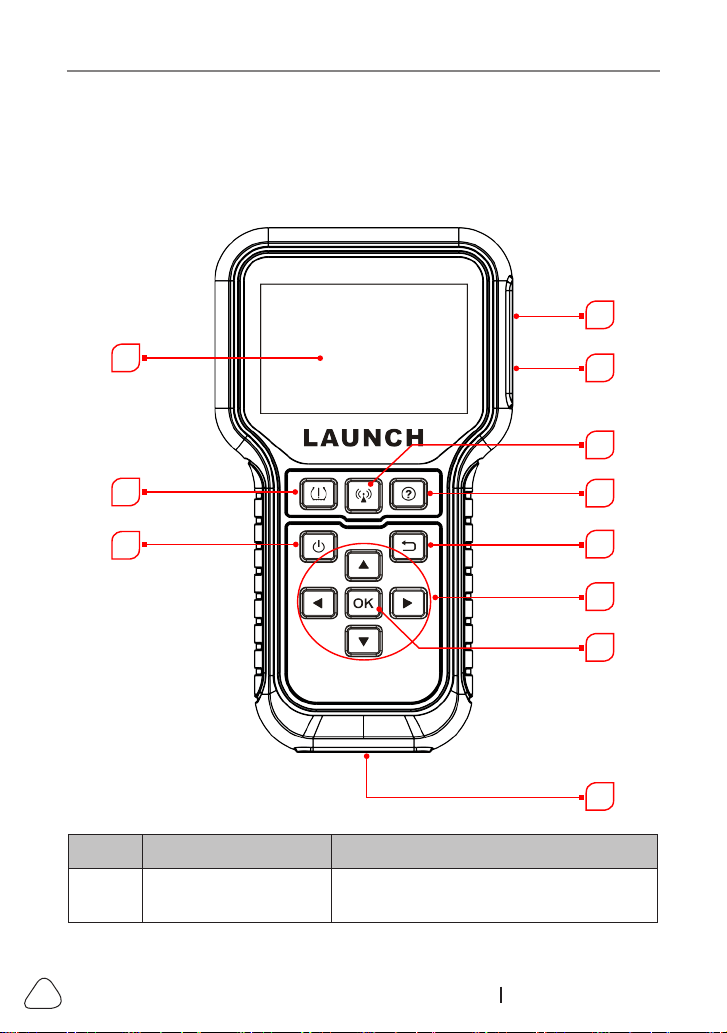
3. Product Descriptions
3.1 General Controls
8
1
2
3
4
5
6
7
9
10
11
No. Name Notes
1
Charging / Data I/O
PORT
Connects the tool to computer via
charging/data cable for upgrade.
LAUNCH
19
www.x431.com +86 755 8455 7891
2
MEMORY CARD
SLOT
Insert the memory card into it to read or
write the data/le stored in the memory
card.
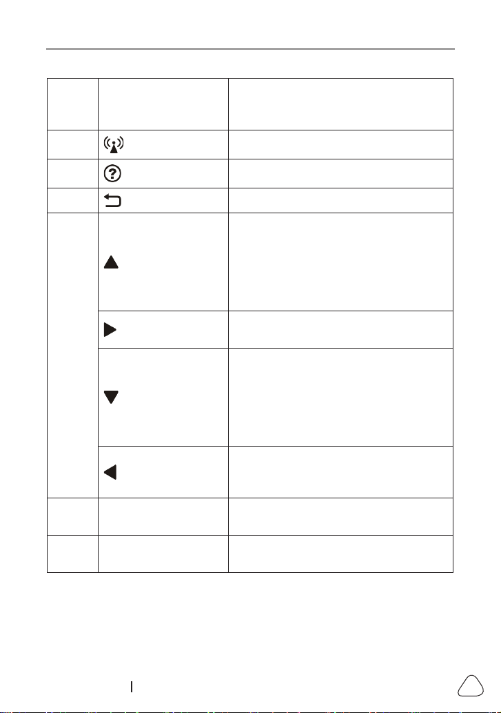
3
BUTTON
Press it to trigger the vehicle sensor.
4
BUTTON
Quick access to Help function.
5
BUTTON
Returns to previous menu.
6
BUTTON
• When in MENU mode, scroll UP
through the menu and submenu line
by line.
• When in DATA VIEW mode, scroll
through the screen data to the
PREVIOUS page.
BUTTON
When in MENU/DATA VIEW mode, scroll
through the screen to the NEXT page.
BUTTON
• When in MENU mode, scroll DOWN
through the menu and submenu line
by line.
• When in DATA VIEW mode, scroll
through the screen data to the NEXT
page.
BUTTON
When in MENU/DATA VIEW mode, scroll
through the screen to the PREVIOUS
page.
7 OK BUTTON
Conrms a selection (or action) from a
MENU list.
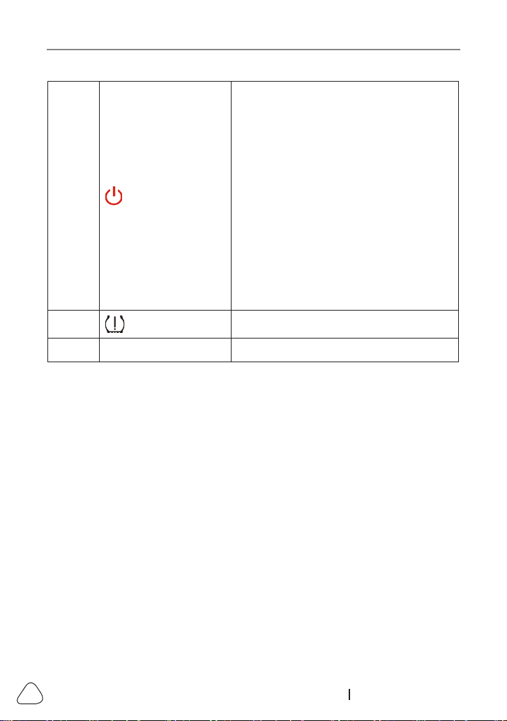
8
DB-15 DIAGNOSTIC
CONNECTOR
Connects the tool to the vehicle’s Data
Link Connector (DLC).
LAUNCH
20
www.x431.com +86 755 8455 7891
9 BUTTON
Press it for about 3 seconds to turn it on.
• Screen On: Press it once to enter
hibernate mode.
• If the tool is not charged and there
is no operation made for the preset
auto power-o interval, it will
automatically power o.
• If the device is charging and there
is no operation made for 5 minutes,
it will automatically enter hibernate
mode to conserve battery power.
• Screen Off (hibernate): Press it once
to wake it up.
Press it for about 8 seconds to turn it o.
10 BUTTON
Quick access to TPMS function.
11 LCD SCREEN
Indicates test results.
3.2 Specications
• Screen: 3.5” LCD display with a resolution of 320*480 pixels
• Input voltage: 9 ~ 18V via OBD diagnostic port / 5V via USB cable
• Operating temperature: 32°F~122°F / 0°C~50°C
• Storage temperature: -4°F~158°F / -20°C ~70°C @ RH60%
• Size: 200*115*35 mm
• Weight: <450g
3.3 Accessories
The following accessory items are only for reference. For dierent destinations,
the accessories may vary. For details, please consult from the local dealers.
1) TPMS Activation & Diagnostic Tool
2) Diagnostic Cable
3) Memory Card
4) Memory Card Adaptor
5) Charging Cable & Power Adaptor

LAUNCH
21
www.x431.com +86 755 8455 7891
6) User Manual
7) Sensors (Optional)

LAUNCH
22
www.x431.com +86 755 8455 7891
4. Initial Use
4.1 Charging & Turning On/O
4.1.1 Charging
There are three methods available for charging the tool.
1. Via AC outlet
Connect one end of the charging cable to the charging port of the tool, and
other end to the power adaptor. Plug the power adaptor into a AC outlet to
start charging.
When charging is finished the charging complete symbol
replaces the
charging symbol. Unplug the power adaptor from the AC outlet and disconnect
the charging cable from the tool.
2. Via Computer
Connect one end of the charging cable to the charging port of the tool, and
other end to a USB port on the computer to start charging.
When charging is finished the charging complete symbol
replaces
the charging symbol. Disconnect the charging cable from the tool and the
computer.
3. Via OBD Diagnostic Port (Not recommended)
If the tool is properly connected to the vehicle’s DLC(Data Link Connector)
port, it will be charged automatically.
Note: Attempting to charge the tool via OBD diagnostic port will consume
vehicle’s baery power. You are not recommended to charge the tool in this way
except for OBD diagnosis operaons.
4.1.2 Turning On/O
Press for about 3 seconds to turn it on.
Press for about 8 seconds to turn it o.
LAUNCH
23
www.x431.com +86 755 8455 7891
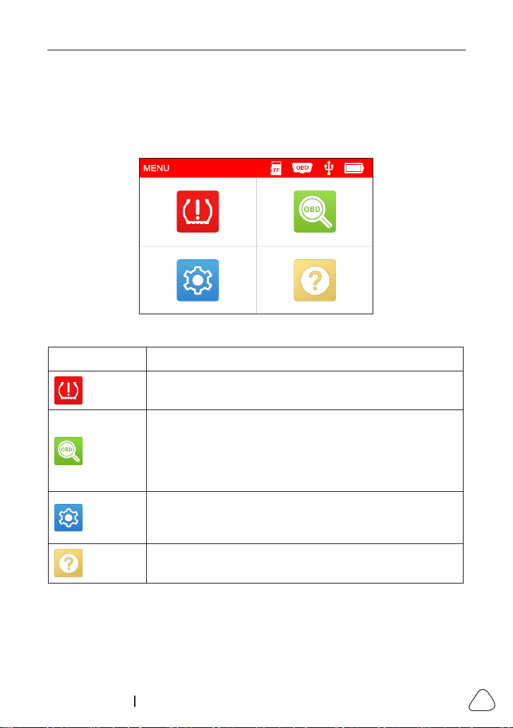
4.2 Main Menu
4.2.1 Function modules
The main menu screen includes the following function modules:
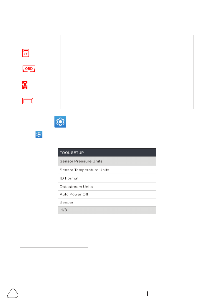
Figure 4-1
Modules Descriptions
TPMS
This function allows you to perform the TPMS sensor
activation, programming and relearning functions.
OBD
This option presents a quick way to check for DTCs,
isolate the cause of the illuminated Malfunction Indicator
Lamp (MIL), check monitor status prior to emissions
certication testing, verify repairs, and perform a number
of other services that are emission-related.
SETUP
Displays the tool setup menu, which lets you make
several adjustments and settings to congure the tool to
your particular needs.
HELP
Helps you have a general knowledge of the DLC location,
tool information etc.
4.2.2 Icons & Symbols
The table below lists some possible on-screen icons and symbols and the
denitions.
LAUNCH
24
www.x431.com +86 755 8455 7891
Icon Descriptions
The memory card is ejected or removed from the memory
card slot.
It appears when the tool is connected to the vehicle’s
DLC port via the diagnostic cable.
It appears when the tool is connected to the PC via the
charging cable.
Battery level indicator
4.3 Settings
Select
on the main menu screen and press [OK], the system will enter the
following screen:
Figure 4-2
1) Sensor Pressure Units
Set the air pressure units of the sensors (kPa, PSI or Bar).
2) Sensor Temperature Units
Set the temperature units of the sensors (C° or F°).
3) ID Format
Change the format of the sensor ID display (Auto, Decimal or Hexadecimal).

LAUNCH
25
www.x431.com +86 755 8455 7891
4) Datastream Units
Set the measurement units of the datastream items (Metric or Imperial).
5) Auto Power O
This option enables you to set the time to turn o the tool automatically after
not being operated.
If the “Disable” option is selected, it will disable this auto power-o function.
6) Beeper
Turn the buzzer to On/O.
7) Region
Set the desired vehicle region when accessing the TPMS module.
8) Language
Congure the system language of the tool to your preference language.
LAUNCH
26
www.x431.com +86 755 8455 7891
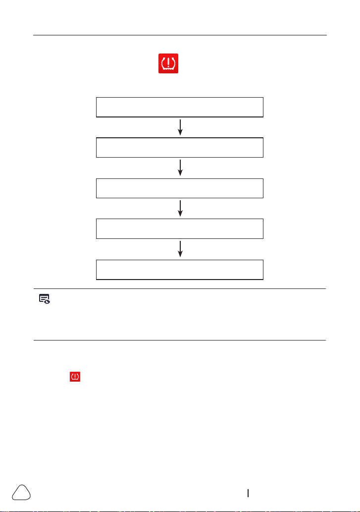
5. TPMS Operations
For initial use, please follow the ow chart below to start using it.
Enter TPMS
Select vehicle manufacturer
Select vehicle model
Select vehicle year
Select the TPMS function
(See *Note)
Note: For indirect TPMS vehicle, only the Relearning function is supported.
For vehicle using Direct TPMS, it generally includes: Acvaon, Programming and
Relearning. The available TPMS functions may vary for different vehicles being
serviced.
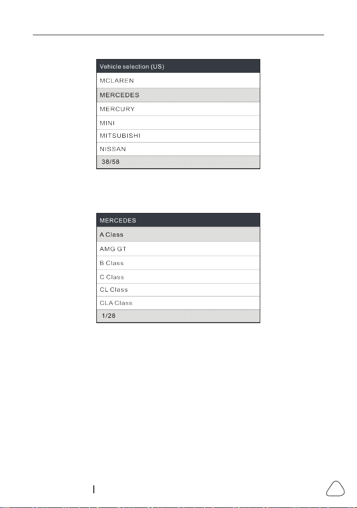
Take
Mercedes Benz
for example to demonstrate how to perform the TPMS
functions.
1. Select on the main menu screen and press the
OK
button to enter the
vehicle selection screen.
LAUNCH
27
www.x431.com +86 755 8455 7891
Figure 5-1 (Select
MERCEDES
)
2. Select
B Class
and press the
OK
button to enter the vehicle year selection
screen.
Figure 5-2 (Select
B Class
)
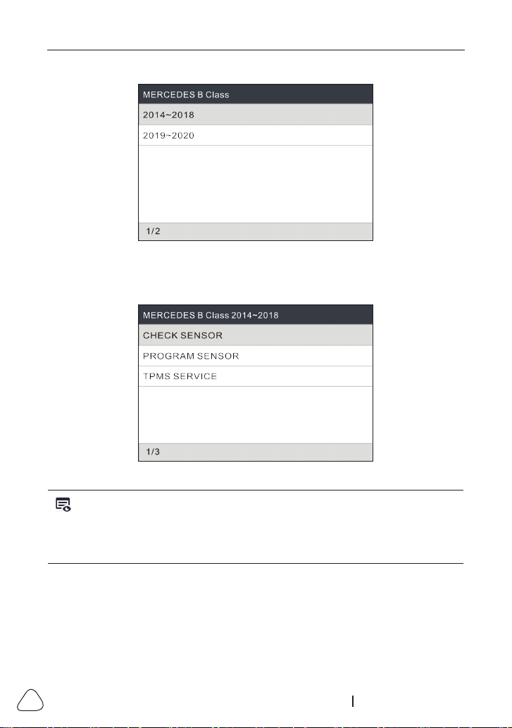
3. Select
2014~2018
and press the
OK
button to enter the TPMS function
selection screen.
LAUNCH
28
www.x431.com +86 755 8455 7891
Figure 5-3 (Select
2014~2018
)
4. Select
2014~2018
and press the
OK
button to enter the TPMS function
selection screen.
Figure 5-4
Note: For indirect TPMS vehicle, only the Learning funcon is supported. For
vehicle using Direct TPMS, it generally includes: Activation, Programming and
Relearning. The available TPMS functions may vary for different vehicles being
serviced.
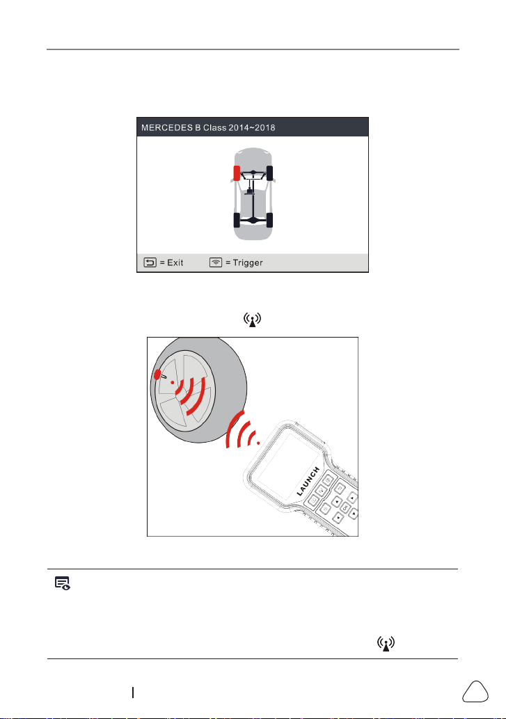
5.1 Check Sensor
This function allows users to activate TPMS sensor to view sensor data
such as sensor ID, tire pressure, tire frequency, tire temperature and battery
condition.
LAUNCH
29
www.x431.com +86 755 8455 7891
1. Select
CHECK SENSOR
and press the
OK
button to enter the following
screen.
Figure 5-5
2. For universal sensors, place the tool alongside the valve stem, point toward
the sensor location, and press the button.
Figure 5-6
Notes:
1. For early magnet-acvated sensors, place the magnet over the stem and then
place the tool alongside the valve stem.
2. If the TPMS sensor requires re deaon (of the order of 10PSI), then deate
the re and place the tool alongside the stem while pressing the buon.
LAUNCH
30
www.x431.com +86 755 8455 7891
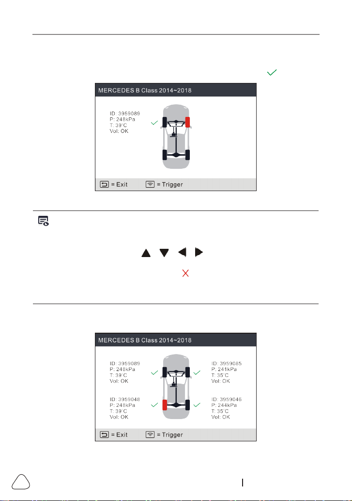
Once the sensor is successfully activated and decoded, the tool will sound
a beep and the screen will display the sensor data with a tick .
Figure 5-7
Notes:
1. The tool will do TPMS test in a sequence of FL (Front Left), FR (Front Right),
RR (Rear Right), LR (Rear Le) and SPARE, if the vehicle has the opon for the
spare. Or, you can use the
/
/
/
button to move to the desired
wheel for tesng.
2. If the sensor fails to be triggered, the icon will appear next to the wheel
posion.
3. If the sensor data is abnormal, it will be displayed in red.
3. Repeat Step 2 for other vehicle sensors. After all sensors are successfully
activated, the following screen will appear:
Figure 5-8
LAUNCH
31
www.x431.com +86 755 8455 7891
*ID
: indicates the sensor ID.
*P
: indicates the tire pressure.
*T
: indicates the tire temperature.
Vol
: indicates the battery power level.
Note: The sensor ID format, the measurement units of the re pressure and
temperature can be set to your preference in the module.
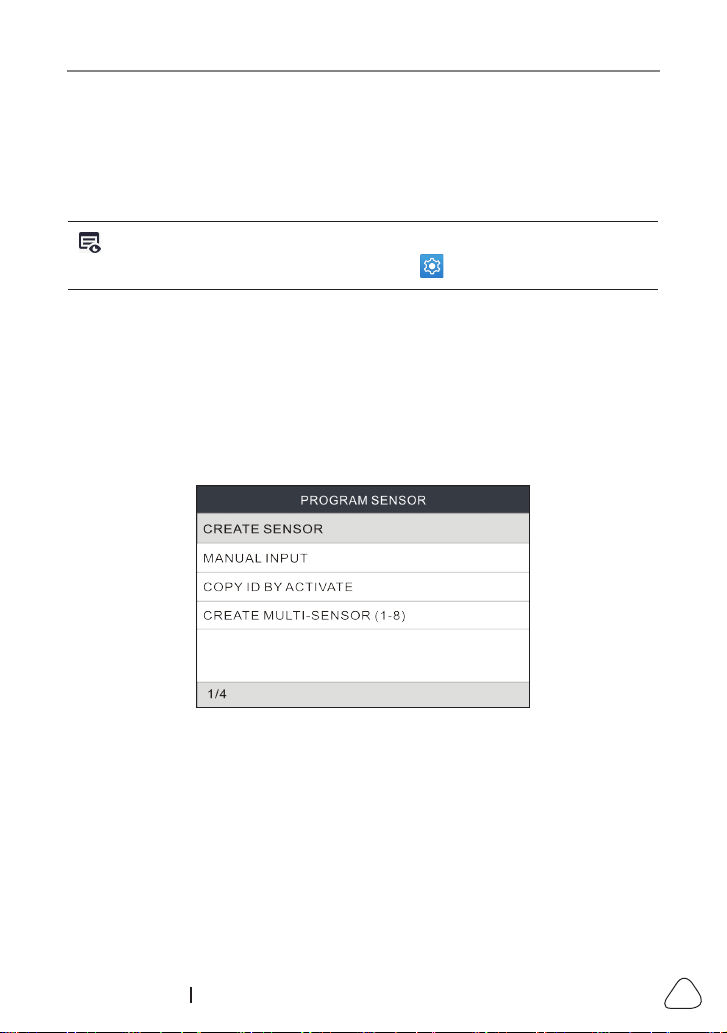
5.2 Program Sensor
This function allows users to program the sensor data to the LAUNCH-sensor
and replace faulty sensor with low battery life or one that is not functioning.
The following options are available for programming LAUNCH-sensor: Auto
Create, Manual Create, Copy ID by Activation and Create Multi-sensor (1-8).
Select
PROGRAM SENSOR
and press the
OK
button to enter the following
screen.
Figure 5-9
5.2.1 Auto create
This function is designed to program the LAUNCH-sensor by applying random
IDs created according to the test vehicle when it is unable to obtain the original
sensor ID.
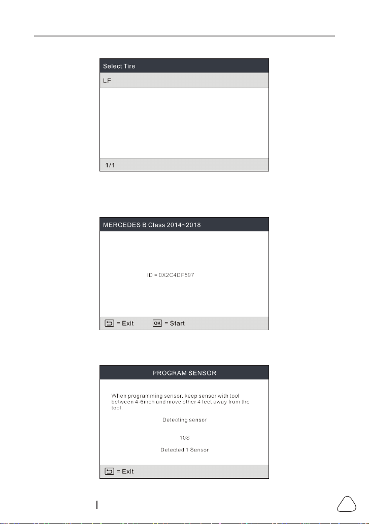
Select the wheel which needs to be programmed on the tool, place a
LAUNCH-sensor close to the TPMS antenna of the tool, and select
CREATE
SENSOR
to create a new random sensor ID.
LAUNCH
32
www.x431.com +86 755 8455 7891
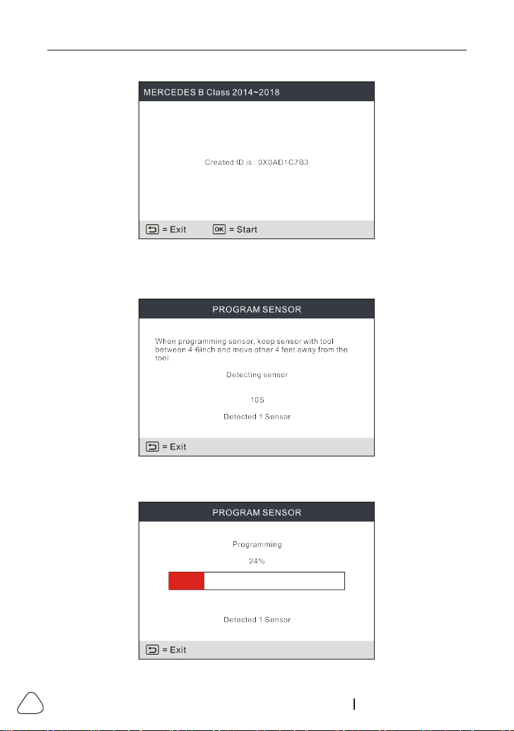
Figure 5-10
Press the
OK
button to start detecting the sensor and writing the new created
sensor ID to the LAUNCH-sensor.
Figure 5-11
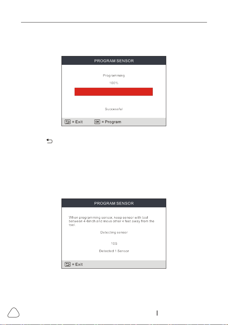
A progress bar will appear on the screen indicating the programming process.
LAUNCH
33
www.x431.com +86 755 8455 7891
Figure 5-12
Once the sensor is successfully programmed, the following screen will appear.
Figure 5-13
Press the button to return to the previous screen. Press the
OK
button to
continue programming other sensors.
Note:If Auto Create is selected, the TPMS Relearn operation needs to be
performed aer programming all required LAUNCH-sensor.
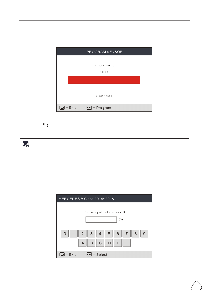
5.2.2 Manual input
This function allows users to manually enter sensor ID. Users can enter the
random ID or the original sensor ID, if it is available.
Select
MANUAL INPUT
to enter the following screen.
Figure 5-14
LAUNCH
34
www.x431.com +86 755 8455 7891
Use the on-screen virtual keypad to input a random or original (if available)
sensor ID and press
OK
.
Figure 5-15
Note: Do not enter the same ID for each sensor.
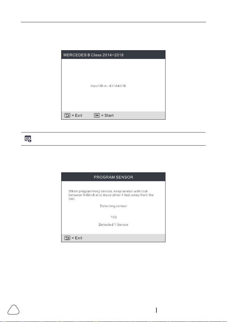
Select the wheel which needs to be programmed on the tool, place a
LAUNCH-sensor close to the TPMS antenna of the tool. Press the
OK
button
to start writing the new sensor ID to the LAUNCH-sensor.
Figure 5-16
A progress bar will appear on the screen indicating the programming process.
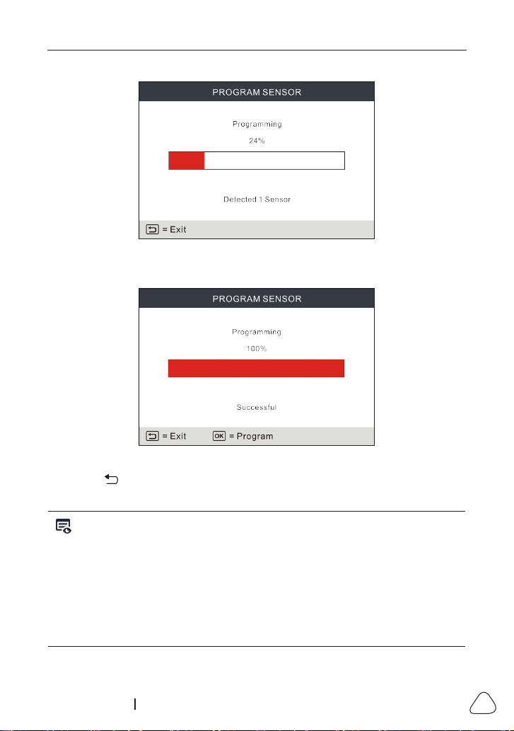
LAUNCH
35
www.x431.com +86 755 8455 7891
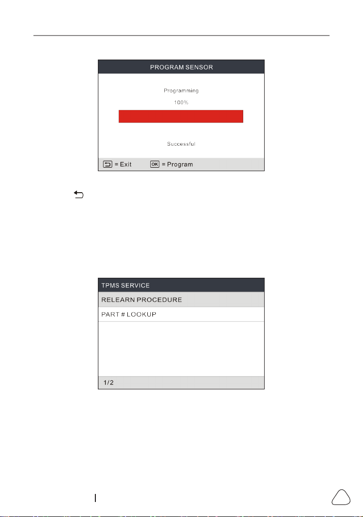
Figure 5-17
After the sensor is successfully programmed, the following screen will appear.
Figure 5-18
Press the button to return to the previous screen. Press the
OK
button to
continue programming other sensors.
Notes:
1. If a random ID is entered, please perform the TPMS Relearn function after
programming is finished. If the original ID is entered, there is no need to
perform Relearn funcon.
2. If a vehicle does not support relearn funcon, please select the Manual Input
opon to enter the original sensor ID manually, or trigger the original sensor at
the acvaon screen to get its informaon, before programming the LAUNCH-
sensor.
LAUNCH
36
www.x431.com +86 755 8455 7891
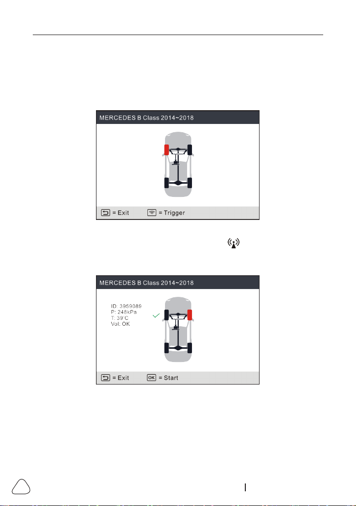
5.2.3 Copy ID by activation
This function allows users to write in the retrieved original sensor data to the
LAUNCH-sensor. It is used after the original sensor is triggered.
Select
COPY ID BY ACTIVATE
and press the
OK
button to enter.
Figure 5-20
Select the specific wheel position and press the button to trigger the
original sensor. After the information is retrieved, it will be displayed on the
screen.
Figure 5-21
Press the
OK
button to continue.
LAUNCH
37
www.x431.com +86 755 8455 7891
Figure 5-22
Select the specic wheel position and press the
OK
button to create a sensor
ID.
Figure 5-23
Press the
OK
button to start writing the new sensor ID to the LAUNCH-sensor.
LAUNCH
38
www.x431.com +86 755 8455 7891
Figure 5-24
After the sensor is successfully programmed, the following screen will appear.
Figure 5-25
Press the button to return to the previous screen. Press the
OK
button to
continue programming other sensors.
5.2.4 Program multi-sensor
This function allows users to program multiple sensors simultaneously. Up to 8
sensors can be programmed at the same time.
Stack up multiple sensors, select
CREATE MULTI-SENSOR (1-8)
to start
programming.
Figure 5-26
After the sensors were successfully programmed, the following screen will
appear.
LAUNCH
39
www.x431.com +86 755 8455 7891
Figure 5-27
Press the button to return to the previous screen. Press the
OK
button to
continue programming other sensors.
5.3 TPMS Service
This function includes two modules: Relearn Procedure and Part Number
Lookup.
Select
TPMS SERVICE
and press the
OK
button to enter the following screen.
Figure 5-28
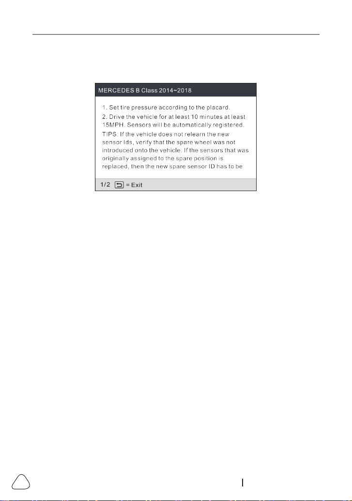
5.3.1 Relearn procedure
This function allows you to check and view the detailed TPMS sensor relearn
procedures.
Relearn operation applies only when the newly programmed sensor IDs are
dierent from the original sensor IDs stored in the vehicle’s ECU. Relearn is
LAUNCH
40
www.x431.com +86 755 8455 7891
used to write the newly programmed sensor IDs into the vehicle’s ECU for
sensor recognition.
Figure 5-29
5.3.2 Part number lookup
This function allows you to check the OE number of the sensors.
LAUNCH
41
www.x431.com +86 755 8455 7891
6. OBD Diagnosing
This option presents a quick way to check for DTCs, isolate the cause of the
illuminated Malfunction Indicator Lamp (MIL), check monitor status prior to
emissions certication testing, verify repairs, and perform a number of other
services that are emission-related.
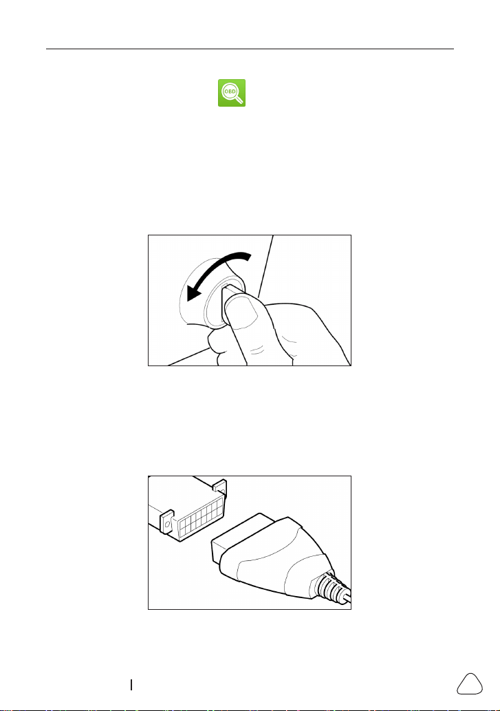
6.1 Connection
1). Turn the ignition o.
Figure 6-1
2). Locate the vehicle’s 16-pin Data Link Connector (DLC). Refer to Chapter
2.4.
3). Plug one end of the diagnostic cable into the vehicle’s DLC(Data Link
Connector) port, and the other end to the DB-15 diagnostic connector of
the tool, and then tighten the captive screws.
Figure 6-2
LAUNCH
42
www.x431.com +86 755 8455 7891
Notes:
• A plasc DLC cover may be found for some vehicles and you need to remove it
before plugging the diagnosc cable.
• The cable connector is keyed and will only t one way. If you have problems
connecng the cable connector to the DLC, rotate the connector 180
o
and try
again.
4). Turn the ignition on. Engine can be o or running.
CAUTION: Don’t connect or disconnect any test equipment with the ignion
on or engine running.
5). The system automatically turns on and navigates to the main menu screen.
6.2 Start OBD Diagnostics
After the tool is properly connected to the vehicle’s DLC, select on the
main menu screen and press
OK
. The tool will automatically start a check of
the vehicle’s computer to determine which type of communication protocol it
is using. When the tool identies the computer’s communication protocol, a
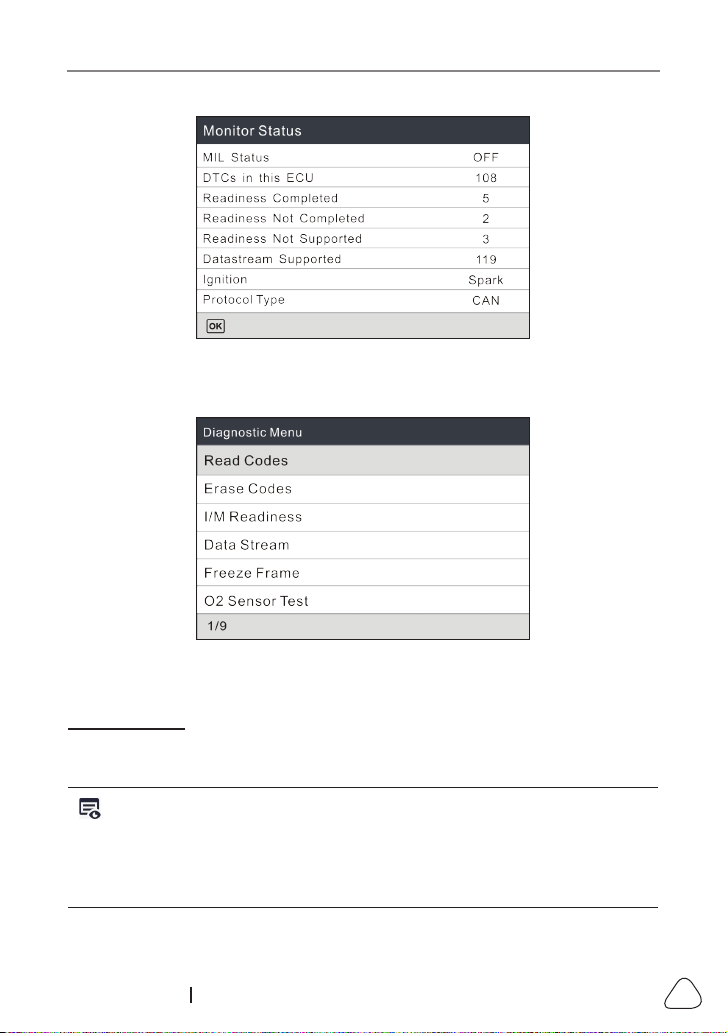
communication link is established and then the screen will display the Monitor
Status.
Note: A PROTOCOL is a set of rules and procedures for regulating data
transmission between computers, and between tesng equipment and computers.
Now ve dierent types of protocols (ISO 9141, Keyword 2000, J1850 PWM, J1850
VPW and CAN) are in use by vehicle manufacturers.
LAUNCH
43
www.x431.com +86 755 8455 7891
Figure 6-3
Press
OK
, the following screen will appear:
Figure 6-4
It mainly includes the following functions:
1. Read Codes
This function allows you to view the Diagnostic Trouble Codes (DTCs)
retrieved from the vehicle’s on-board computer.
Note: Never replace a part based only on the DTC definition. Each DTC has
a set of testing procedures, instructions and flow charts that must be followed
to conrm the locaon of the problem. This informaon is found in the vehicle’s
service manual. Always refer to the vehicle’s service manual for detailed tesng
instrucons.
Select
Read Codes
from the Diagnostic Menu and press
OK
. The system will
LAUNCH
44
www.x431.com +86 755 8455 7891
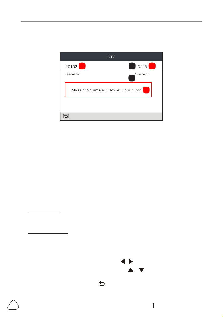
automatically read the SAE-standard DTCs and a screen similar to Figure 6-5
will appear.
A B C
D
E
Figure 6-5
In Figure 6-3,
• A - DTC
: Displays the Diagnostic Trouble Code (DTC) number. Each fault
is assigned a code number that is specic to that fault.
• B - Code Number Sequence
: The tool assigns a sequence number to
each DTC that is present in the computer’s memory, starting with “1.” This
number indicates which code is currently displayed.
• C - Code Enumerator
: Indicates the total number of codes retrieved from
the vehicle’s computer.
• D - Code Type
: Indicates the type of code being displayed: Generic
Current, Generic Pending, Generic Permanent, etc.
Pending DTC: A code recorded on the “rst trip” for a “two-trip” code. If the
fault that caused the code to be set is not detected on the second trip, the
code is automatically erased.
Permanent DTC: It indicates there is a problem in one or more of the
vehicle’s systems. In this case, the Malfunction Indicator (“Check Engine”)
lamp on the vehicle’s instrument panel will light steady on.
• E - Test Data Display Area
: Displays DTC denitions.
If more than one DTC was retrieved, press / to view dierent DTCs.
In the case of long code definitions, use / to view the additional
information.
After viewing all the codes, press to return to Diagnostic Menu.
LAUNCH
45
www.x431.com +86 755 8455 7891
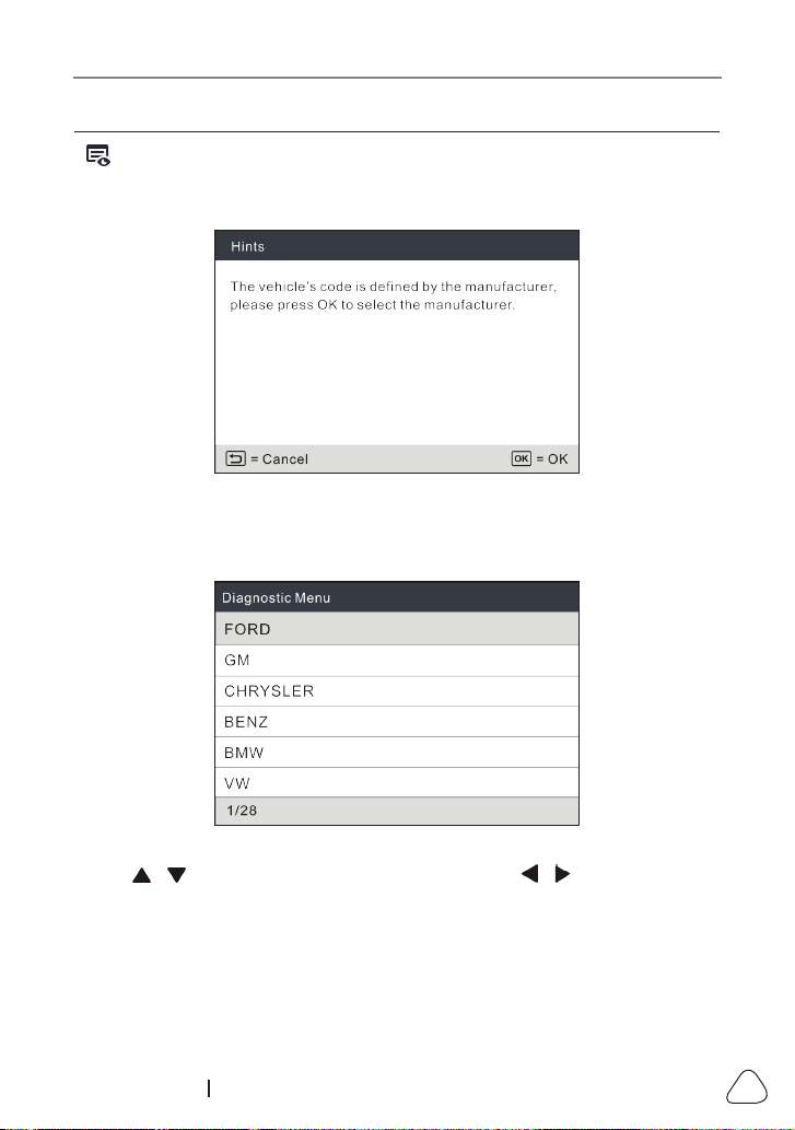
Note: In case the diagnosc codes are manufacturer-specic, users need to
select the manufacturer manually and the following prompt message will appear
on the screen.
Figure 6-6
Press OK to enter to select the manufacturer. Figure 6-7 will be shown on the
screen.
Figure 6-7
Press
/
to select dierent manufacturer; press the
/
buon to turn to
next or previous page. Aer selecng the desired one, press OK to conrm.
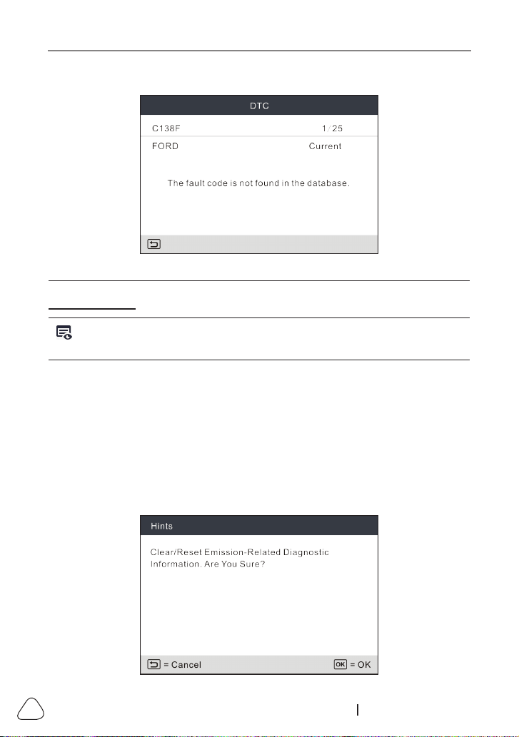
• If some DTCs are found, the screen will display the DTCs (Refer to Figure 6-5).
• If the DTC can not be found, a screen similar to the following gure will appear:
LAUNCH
46
www.x431.com +86 755 8455 7891
Figure 6-8
2. Erase Codes
Note: When this funcon is used to erase DTCs from the vehicle’s on-board
computer, “Freeze Frame” data is erased and “Permanent” DTCs ARE NOT erased.
If you plan to take the vehicle to a Service Center for repair,
DO NOT
erase
the codes from the vehicle’s computer. If data is erased, valuable information
that might help the technician troubleshoot the problem will also be erased.
After reading the retrieved codes from the vehicle and certain repairs have
been carried out, you can use this function to erase the codes from the
vehicle. Before performing this function, please be sure the vehicle’s ignition
key is in the ON position with the engine o.
Select
Erase Codes
from the Diagnostic Menu and press
OK
, the following
screen will appear:
LAUNCH
47
www.x431.com +86 755 8455 7891
Figure 6-9
Press
OK
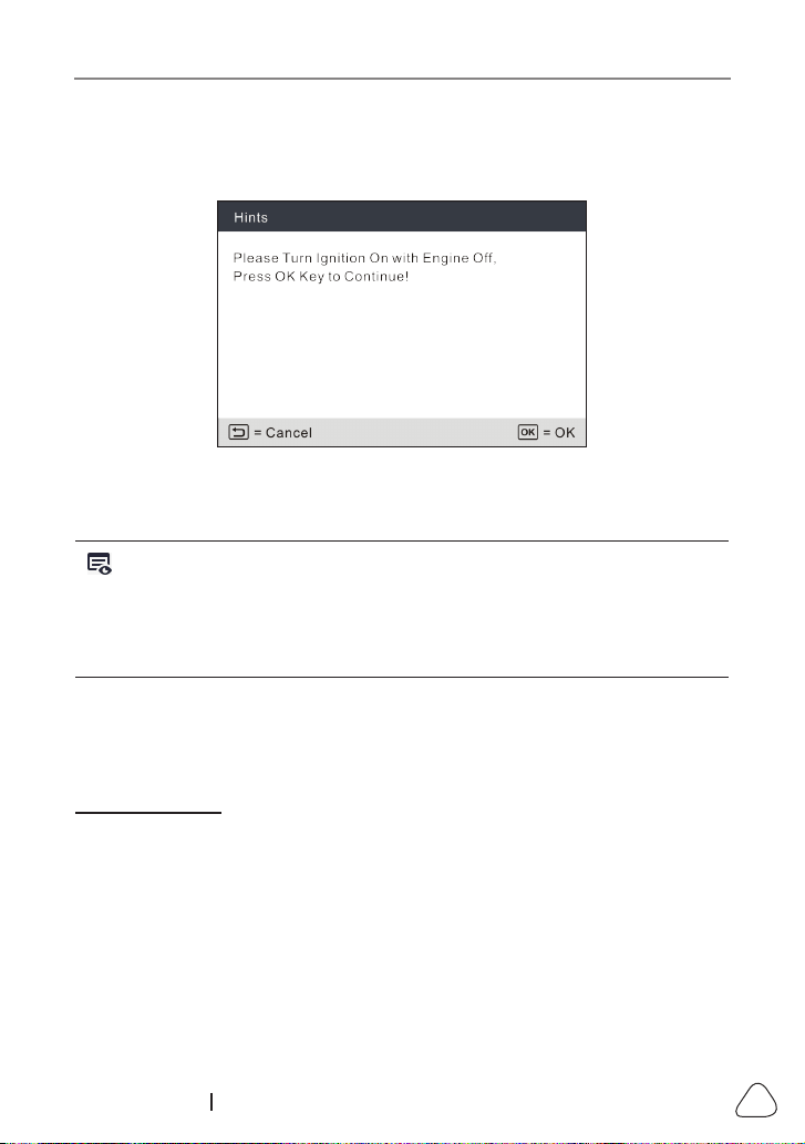
to erase DTCs, and the following screen will appear:
Figure 6-10
Follow the on-screen prompts to turn the ignition on with engine o, press
OK
to clear the DTCs.
Note: When data is erased from the vehicle’s computer memory, the I/M
Readiness Monitor Status program resets the status of all Monitors to a “Not
Completed” status. To set all of the Monitors to a “Completed” status, an OBD
II Drive Cycle must be performed. Refer to your vehicle’s service manual for
informaon on how to perform an OBD II Drive Cycle for the vehicle under test.
After clearing, you should retrieve trouble codes once more or turn ignition on
and retrieve codes again. If there are still some trouble codes in the system,
please troubleshoot the code using a factory diagnosis guide, then clear the
code and recheck.
3. I/M Readiness
I/M refers to Inspection and Maintenance that is legislated by the Government
to meet federal clean-air standards. I/M Readiness indicates whether or not
the various emissions-related systems on the vehicle are operating properly
and are ready for Inspection and Maintenance testing.
The purpose of the I/M Readiness Monitor Status is to indicate which of the
vehicle’s Monitors have run and completed their diagnosis and testing, and
which ones have not yet run and completed testing and diagnosis of their
designated sections of the vehicle’s emissions system.
The I/M Readiness Monitor Status function also can be used (after repair of
LAUNCH
48
www.x431.com +86 755 8455 7891
a fault has been performed) to confirm that the repair has been performed
correctly, and/or to check for Monitor Run Status.
Select
I/M Readiness
from the Diagnostic Menu and press
OK
, the screen will
display the I/M readiness result.
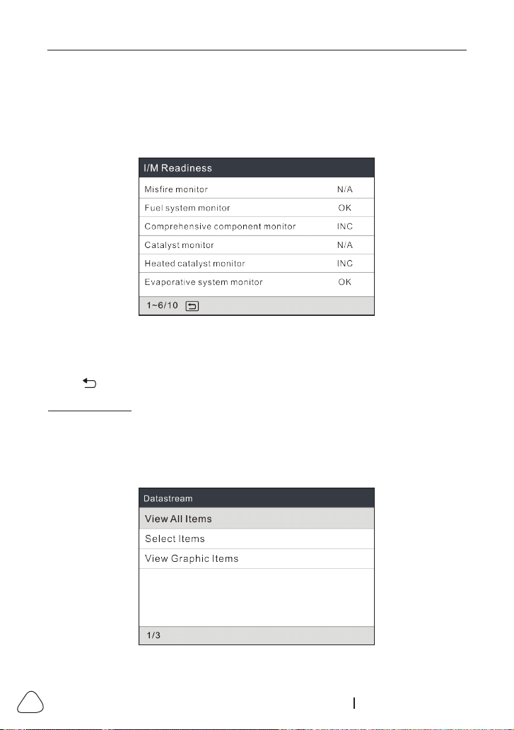
Figure 6-11
N/A means not available on this vehicle, INC means incomplete or not ready,
OK means Completed or Monitor OK.
Press to return to Diagnostic Menu.
4. Data Stream
This option retrieves and displays live data and parameters from the vehicle’s
ECU.
Select
Data Stream
from the Diagnostic Menu and press
OK
, the following
screen will appear.
Figure 6-12
LAUNCH
49
www.x431.com +86 755 8455 7891
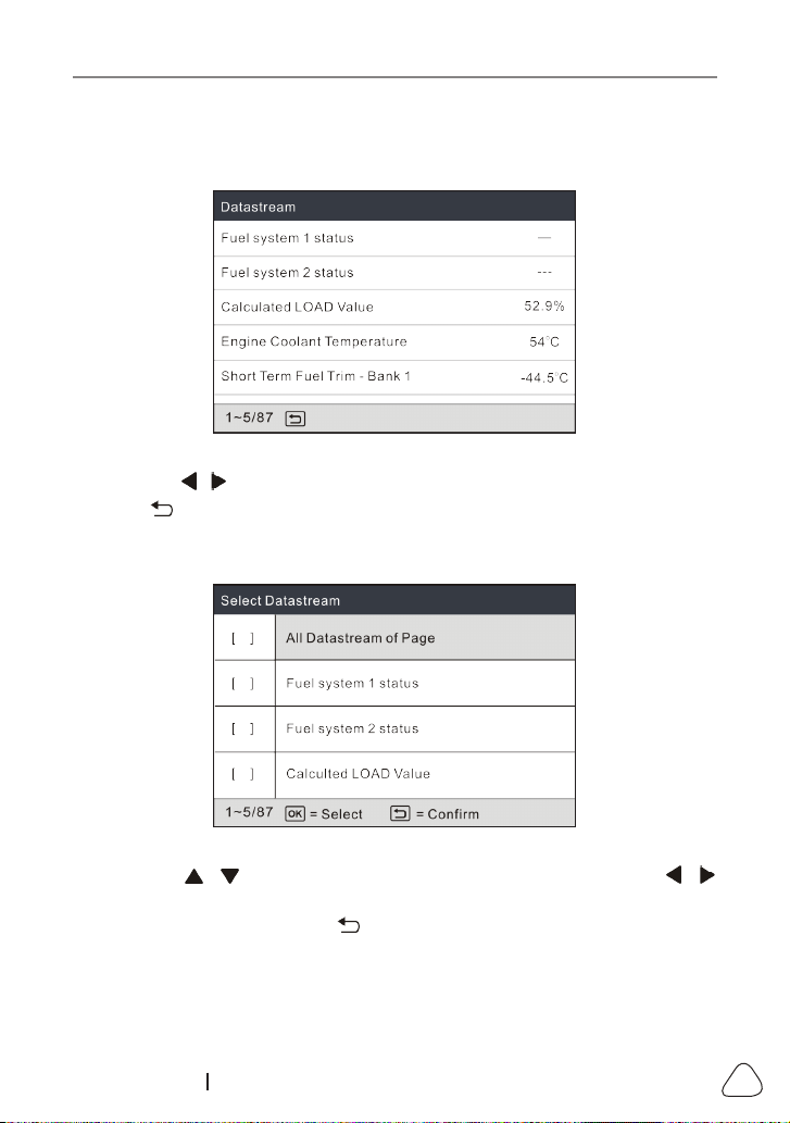
• Select
View All Items
and press
OK
, the screen will display the dynamic
data of all data stream items:
Figure 6-13
Press the / button to turn page to view other data streams.
Press to return to Diagnostic Menu.
• Select
Select Items
in Data stream menu and press
OK
, the following
screen will appear:
Figure 6-14
Press the / button to check data stream items, and press the /
button to turn page.
After selecting items, press , the screen will display the selected data
stream items.
To select all data stream of the current page, check the option “All
Datastream of Page” and press
OK
, √ will appear before all items. To
deselect all, just press
OK
again.

LAUNCH
50
www.x431.com +86 755 8455 7891
• If
View Graphic Items
is selected in Data stream menu and press
OK
to
enter the graphic items selection screen.
Press the / button to select single data stream items, and press
OK
button, the screen will display the selected items of live graphic data.
Press to return to Diagnostic Menu..
5. View Freeze Frame
When an emission-related fault occurs, certain vehicle conditions are recorded
by the on-board computer. This information is referred to as freeze frame
data. Freeze Data is a snapshot of the operating conditions at the time of an
emission-related fault.
Note: if DTCs were erased, Freeze Data may not be stored in vehicle memory
depending on vehicle.
6. O
2
sensor test
OBD II regulations require that applicable vehicles monitor and test operation
of the oxygen (O
2
) sensors to identify problems that can aect fuel eciency
and vehicle emissions. These tests are performed automatically when engine
operating conditions are within predefined limits. Results of these tests are
stored in the on-board computer’s memory.
The O
2
Sensor Test function lets you retrieve and view O
2
sensor monitor test
results for the most recently completed tests from your vehicle’s on-board
computer.
7. On-board monitor test
This function can be utilized to read the results of on-board diagnostic
monitoring tests for specic components/systems.
8. EVAP System Test
The EVAP test function lets you initiate a leak test for the vehicle’s EVAP
system. This tool does not perform the leak test, but signals to vehicle’s on-
board computer to initiate the test. The vehicle manufacturer determines the
criteria and method for stopping the test once it has been started. Before
using the system test function, refer to the vehicle’s service repair manual to
determine the procedures necessary to stop the test.
9. Vehicle Info
Select
Vehicle Info
from the Diagnostic Menu and press
OK
, the tool will

LAUNCH
51
www.x431.com +86 755 8455 7891
retrieve a list of information (provided by the vehicle manufacturer) from the
vehicle’s on-board computer. This information may include:
• VIN
(Vehicle identication Number). It is applicable to model year 2000 and
newer OBD II-compliant vehicles.
• CID
(Calibration ID). These IDs uniquely identify the software version(s) for
the vehicle’s control module(s).
• CVN
(Calibration Verification Number). CVNs are used to determine if
emission-related calibrations for the vehicle under test have been changed.
One or more CVNs may be returned by the vehicle’s computer.
LAUNCH
52
www.x431.com +86 755 8455 7891
7. Help
This menu enables you to view device information and OBD introduction.
On the main menu screen, select and press
OK
to enter the following
screen.
Figure 7-1
7.1 DLC Location Information
This option helps you to nd the location of the vehicle’s DLC.
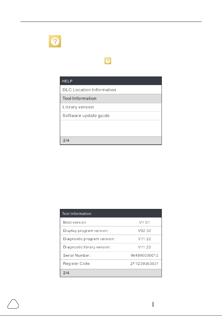
7.2 Tool Information
In Figure 7-1, select
Tool Information
and press
OK
to view the related
information of the tool.
Figure 7-2

LAUNCH
53
www.x431.com +86 755 8455 7891
Note: You are strongly recommended to note down the Serial Number and
Register Code in Figure 7-2 since these 2 pieces of informaon are required while
registering your tool.
Press to return to the previous screen.
7.3 Library Version
This option allows you to view the database and relearn procedure version.
7.4 Software Update Guide
This option introduces brief operation steps on how to update the diagnostic
software.
LAUNCH
54
www.x431.com +86 755 8455 7891
8. Register & Update
Prerequisite conditions:
1. Go to http://www.x431.com/CRT511 to download the update tool and install
it on the computer.
2. System requirements: Windows XP, 7, 8 or Windows 10.
The tool can be updated via memory card.
1. Note down the Serial Number and Register code.
1). Connect one end of the USB cable to your tool, and the other end on the
computer.
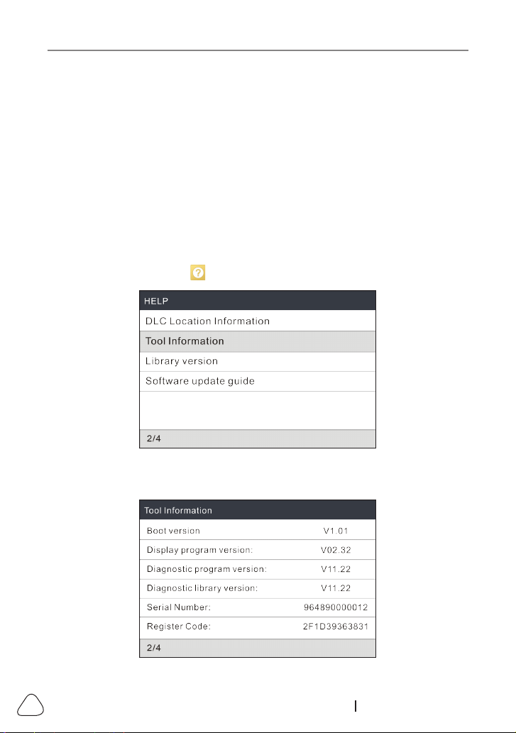
2). After the tool has powered up and entered the main menu screen, move
the highlight bar on the icon and press
OK
.
Figure 8-1
3). Highlight the
Tool Information
and press
OK
.
LAUNCH
55
www.x431.com +86 755 8455 7891
Figure 8-2
4). Write down the Serial Number and Register code for later use.
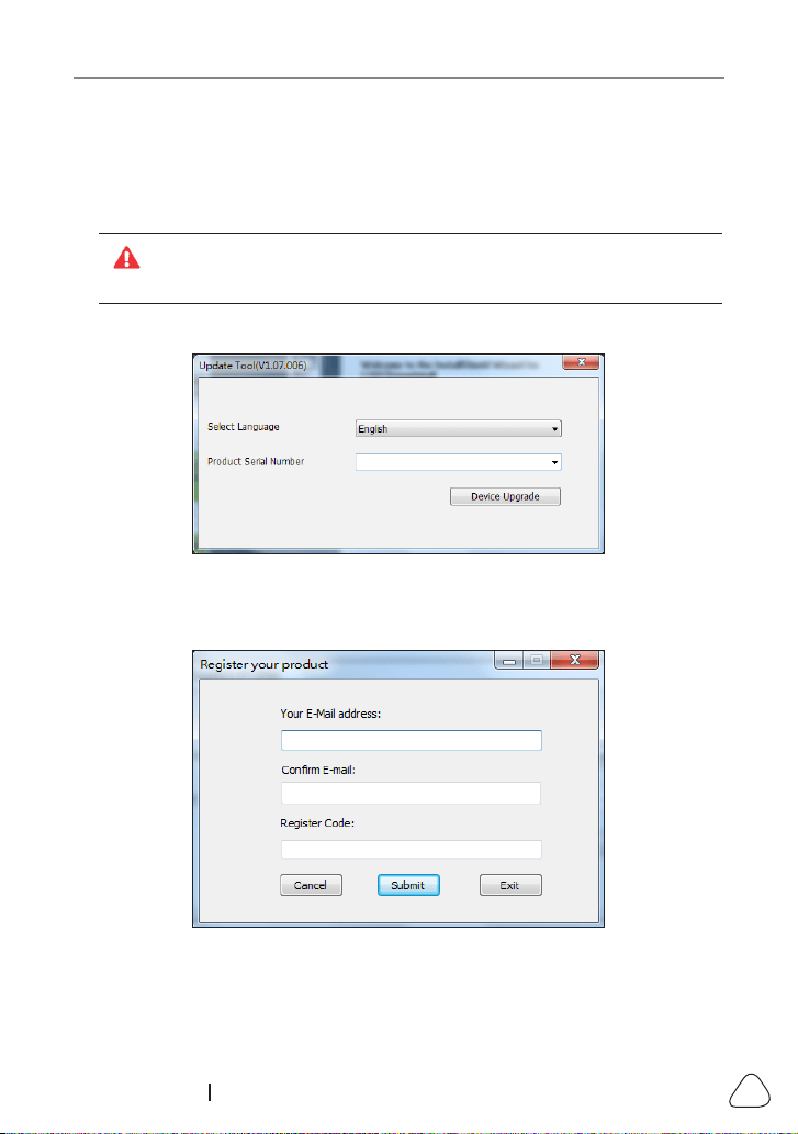
2. Register the scanner on the update tool .
For beer experience, it is recommended to register and upgrade the tool
rst. But if not, the tool can also be used normally.
1). Launch the update tool, the following screen will appear:
Figure 8-3
2). Select the target language and enter the Serial Number, click
Device
Upgrade
, the following screen will appear.
Figure 8-4
3). Enter the required E-mail address and Register Code, click
Submit
to nish
the sign-up.

LAUNCH
56
www.x431.com +86 755 8455 7891
Note: For inial update, user needs to go through a registraon process.
Once you nished it, the registraon screen will not appear again each me
you click the Device Upgrade buon in the future.
3. Copy the update package into the memory card.
1). Install the memory card from the tool into the supplied memory card
adaptor and insert it into the USB port of the computer.
2). Reopen the update tool, select the updates you would like to perform or
click
Select All
, and then click
Download
to start downloading the update
package into the memory card.
4. Reinsert the memory card into the tool and start update.
1).Once all steps are complete, reinsert the memory card into the tool and
power up the tool via USB cable.
2). The tool starts verifying the consistence of the local les with the les in the
memory card. If dierence exists, the tool will automatically start updating
and a green update progress bar will appear on the bottom of the screen.
Be patient to wait until the update is completely nished.

LAUNCH
57
www.x431.com +86 755 8455 7891
9. FAQ
Here we list some frequently asked questions and answers relating to this tool.
Question
: System halts when reading data stream. What is the reason?
Answer
: It may be caused by a slackened connector. Please turn o the tool,
rmly connect the connector, and switch it on again.
Question
: What to do when encountering screen flickering or font damage
during use?
Answer
: This bug can be xed ONLY by doing the following:
1. Keep the memory card inserted into the tool and then connect the tool to
the PC via USB cable.
2. The system will automatically upgrade the rmware and then reboot.
Note: Although the tool can get power from vehicle’s OBD II port via the
diagnosc cable, it only allows users to perform vehicle diagnoscs. It does not
apply to soware update or rmware x operaon.
Do not aempt to connect the tool to the vehicle’s OBD II port to x this bug.
Question
: Screen of main unit ashes at engine ignition start.
Answer
: Caused by electromagnetic disturbing, and this is normal
phenomenon.
Question
: There is no response when communicating with on-board
computer.
Answer
: Please conrm the proper voltage of power supply and check if the
throttle has been closed, the transmission is in the neutral position, and the
water is in proper temperature.
Question
: Why are there so many fault codes?
Answer
: Usually, it’s caused by poor connection or fault circuit grounding.
Question
: What to do if the tool fails to boot up?
Answer
: Please connect the tool to the USB port of a computer to fix the
rmware.

LAUNCH
58
www.x431.com +86 755 8455 7891
Warranty
THIS WARRANTY IS EXPRESSLY LIMITED TO PERSONS WHO
PURCHASE LAUNCH PRODUCTS FOR PURPOSES OF RESALE OR USE
IN THE ORDINARY COURSE OF THE BUYER’S BUSINESS.
LAUNCH electronic product is warranted against defects in materials and
workmanship for one year (12 months) from date of delivery to the user.
This warranty does not cover any part that has been abused, altered, used
for a purpose other than for which it was intended, or used in a manner
inconsistent with instructions regarding use. The exclusive remedy for any
automotive meter found to be defective is repair or replacement, and LAUNCH
shall not be liable for any consequential or incidental damages.
Final determination of defects shall be made by LAUNCH in accordance with
procedures established by LAUNCH. No agent, employee, or representative of
LAUNCH has any authority to bind LAUNCH to any armation, representation,
or warranty concerning LAUNCH automotive meters, except as stated herein.
Order Information
Replaceable and optional parts can be ordered directly from your LAUNCH
authorized tool supplier. Your order should include the following information:
1. Quantity
2. Part number
3. Item description
Customer Service
If you have any questions on the operation of the unit, please contact local
dealer, or contact LAUNCH TECH. CO., LTD:
Tel: +86-755-84527891
E-mail: [email protected]
