
i
LAUNCH Series User Manual
WARNING
Study, understand and follow all instructions provided with this product. Read
these instructions carefully before installing, operating, servicing or repairing
this tool. Keep these instructions in a safe, accessible place.
Caution: To help prevent personal injury,
• Never use this tool for any application other than for which it was
designed.
• Never alter or modify this tool in any way. Improper operation and / or
maintenance of the tool, or modication of the tool could result in serious
injury or death.
• Always perform automotive testing in a safe environment.
• Do not attempt to operate or observe the tool while driving a vehicle.
Operating or observing the tool will cause driver distraction and could
cause a fatal accident.
• Wear safety eye protection that meets ANSI standards.
• Keep clothing, hair, hands, tools, test equipment, etc. away from all
moving or hot engine parts.
• Operate the vehicle in a well-ventilated work area: Exhaust gases are
poisonous.
• Put blocks in front of the drive wheels and never leave the vehicle
unattended while running tests.
• Use extreme caution when working around the ignition coil, distributor
cap, ignition wires and spark plugs. These components create hazardous
voltages when the engine is running.
• Put the transmission in P (for A/T) or N (for M/T), and make sure the
parking brake is engaged.
• Keep a re extinguisher suitable for gasoline / chemical / electrical res
nearby.
• Don’t connect or disconnect any test equipment while the ignition is on or
the engine is running.
• Keep this tool dry, clean, free from oil / water or grease. Use a mild
detergent on a clean cloth to clean the outside of the tool, when necessary.

ii
LAUNCH Series User Manual
FCC STATEMENT
Any Changes or modications not expressly approved by the party
responsible for compliance could void the user’s authority to operate the
equipment.
This device complies with part 15 of the FCC Rules. Operation is subject
to the following two conditions: (1) This device may not cause harmful
interference, and (2) this device must accept any interference received,
including interference that may cause undesired operation.
Note: This equipment has been tested and found to comply with the limits for
a Class B digital device, pursuant to Part 15 of the FCC Rules. These limits
are designed to provide reasonable protection against harmful interference in
a residential installation.
This equipment generates, uses, and can radiate radio frequency energy,
and if not installed and used in accordance with the instructions, may cause
harmful interference to radio communications. However, there is no guarantee
that interference will not occur in a particular installation. If this equipment
does cause harmful interference to radio or television reception, which can be
determined by turning the equipment o and on, the user is encouraged to try
to correct the interference by one or more of the following measures:
- Reorient or relocate the receiving antenna.
- Increase the separation between the equipment and receiver.
- Connect the equipment into an outlet on a circuit dierent from that to
which the receiver is connected.
- Consult the dealer or an experienced radio / TV technician for help.

iii
LAUNCH Series User Manual
Table of Contents
1. Introduction .................................................................................................... 1
2. General Information ...................................................................................... 3
2.1 On-Board Diagnostics (OBD) II ..................................................................... 3
2.2 Diagnostic Trouble Codes (DTCs) ................................................................. 3
2.3 Location of the Data Link Connector (DLC)................................................... 4
2.4 OBD II Readiness Monitors ........................................................................... 5
2.5 OBD II Monitor Readiness Status.................................................................. 6
2.6 OBD II Denitions .......................................................................................... 6
3. Product Descriptions .................................................................................... 8
3.1 Components & Controls ................................................................................ 8
3.2 Technical Specications ................................................................................ 9
3.3 Accessories Checklist .................................................................................... 9
4. Initial Use...................................................................................................... 10
4.1 Powering Up The Tool ................................................................................. 10
4.2 Getting Started ............................................................................................ 10
4.3 Job Menu ......................................................................................................11
5. Diagnose ...................................................................................................... 13
5.1 Connection .................................................................................................. 13
5.2 System Diagnosing...................................................................................... 14
5.2.1 Smart Diagnosis (Auto-Detect) ................................................................. 14
5.2.2 Manual Diagnosis ..................................................................................... 15
5.3 OBDII Diagnosis .......................................................................................... 23
5.4 History ......................................................................................................... 25
5.5 Reset (Special Functions) .......................................................................... 26
5.5.1 Download reset software .................................................................... 26
5.5.2 How to perform reset procedures? ..................................................... 27
6. Upgrade ........................................................................................................ 28
7. Mall................................................................................................................ 29
8. Settings ........................................................................................................ 30
8.1 Units of measurement ................................................................................. 30

iv
LAUNCH Series User Manual
8.2 Automatic detection on connect................................................................... 30
8.3 Brightness.................................................................................................... 30
8.4 Sound .......................................................................................................... 30
8.5 Network ....................................................................................................... 30
8.6 Time Zone.................................................................................................... 30
8.7 Language..................................................................................................... 30
8.8 Workshop information .................................................................................. 31
8.9 Recovery ..................................................................................................... 31
8.10 Clean Up.................................................................................................... 31
8.11 Screen Capture .......................................................................................... 31
8.12 About ......................................................................................................... 31
8.13 Data ........................................................................................................... 31
8.13.1 Diagnostic Record ............................................................................ 31
8.13.2 Diagnostic Report ............................................................................. 32
8.13.3 DTC Library ...................................................................................... 32
8.13.4 DLC (Data Link Connector) Location................................................ 33
8.13.5 Image................................................................................................ 33
8.13.6 Feedback .......................................................................................... 33
8.13.7 Firmware Fix ..................................................................................... 34
8.13.8 User Manual ..................................................................................... 34
9. FAQ ............................................................................................................... 35

1
LAUNCH Series User Manual
1. Introduction
Creader Elite 300/302/305/310 is an evolutionary smart code reader for
professional technicians or DIYers. It only applies to the passenger cars with 12V
battery voltage.
It has the following functions and advantages:
• Smart(Auto-Detect) Diagnosis: Once the tool and the vehicle are properly
connected, the system starts auto-detect process. Once the whole process is
successfully nished, a diagnostic report will be automatically generated.
• Manual Diagnosis: If Auto-Detect failure occurs, manual diagnosis is also
available. Diagnosis functions include: Version Information, Read DTCs,
Clear DTCs and Read Data Stream (supports 3 display modes: Value, Graph
and Merged).
• OBD II Diagnosis: 10 modes of OBD II test are supported, including EVAP,
O2 Sensor, I/M Readiness, MIL Status, VIN Info, and On-board monitors
testing etc.
• Reset: This function allows you to perform dierent kinds of common special
functions.
• One-Click Update: Let you update your diagnostic software and APK online.
• Mall: This function allows you to purchase more diagnostic software with full
system and full functions that are not pre-installed on this tool.
• Diagnostic History: This function provides a quick access to the tested
vehicles and users can choose to view the test report or resume from the last
operation, without starting from scratch.
• Diagnostic Feedback: Use this option to submit the vehicle issue to us for
analysis and troubleshooting.
• DTC Library: Allows you to retrieve the definition of the diagnostic trouble
code from the abundant DTC database.
• Displays battery real-time voltage once properly connected to the vehicle.
This tool is specially designed to work with all OBD II compliant vehicles,
including Controller Area Network (CAN). It is required by EPA that all 1996 and
newer vehicles (cars and light trucks) sold in the United States must be OBD II
compliant and this includes all American, Asian and European vehicles.
A small number of 1994 and 1995 model year gasoline vehicles are OBD II
compliant. To verify if a 1994 or 1995 vehicle is OBD II compliant, check the
following:
1. Vehicle Emissions Control Information (VECI) Label. It is located under the
hood or by the radiator of most vehicles. If the vehicle is OBD II compliant,
2
LAUNCH Series User Manual
the label will designate “OBD II Certied”.
2. Government regulations mandate that all OBD II compliant vehicles must
have a “common” 16-pin Data Link Connector (DLC).
Note: Some 1994 and 1995 vehicles have 16-pin connectors but are not OBD
II compliant. Only those vehicles with a Vehicle Emissions Control Label stating
“OBD II Certied” are OBD II compliant.

3
LAUNCH Series User Manual
2. General Information
2.1 On-Board Diagnostics (OBD) II
The first generation of On-Board Diagnostics (OBD I) was developed by the
California Air Resources Board (ARB) and implemented in 1988 to monitor some
of the emission control components on vehicles. As technology evolved and the
desire to improve the On-Board Diagnostic system increased, a new generation
of On-Board Diagnostic system was developed. This second generation of On-
Board Diagnostic regulations is called “OBD II”.
The OBD II system is designed to monitor emission control systems and key
engine components by performing either continuous or periodic tests of specic
components and vehicle conditions. When a problem is detected, the OBD II
system turns on a warning lamp (MIL) on the vehicle instrument panel to alert
the driver typically by the phrase of “Check Engine” or “Service Engine Soon”.
The system will also store important information about the detected malfunction
so that a technician can accurately nd and x the problem. Here below follow
three pieces of such valuable information:
1) Whether the Malfunction Indicator Light (MIL) is commanded ‘on’ or ‘o’;
2) Which, if any, Diagnostic Trouble Codes (DTCs) are stored;
3) Readiness Monitor status.
2.2 Diagnostic Trouble Codes (DTCs)
OBD II Diagnostic Trouble Codes are codes that are stored by the on-board
computer diagnostic system in response to a problem found in the vehicle. These
codes identify a particular problem area and are intended to provide you with a
guide as to where a fault might be occurring within a vehicle. OBD II Diagnostic
Trouble Codes consist of a five-digit alphanumeric code. The first character,
a letter, identifies which control system sets the code. The second character,
a number, 0-3; other three characters, a hex character, 0-9 or A-F provide
additional information on where the DTC originated and the operating conditions
that caused it to set. Here below is an example to illustrate the structure of the
digits:

4
LAUNCH Series User Manual
Figure 2-1 (P0201 - Injector circuit malfunction, Cylinder 1)
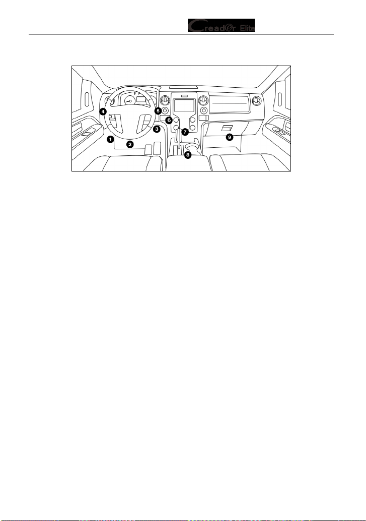
2.3 Location of the Data Link Connector (DLC)
The DLC (Data Link Connector or Diagnostic Link Connector) is typically a 16-
pin connector where diagnostic code readers interface with the vehicle’s on-
board computer. The DLC is usually located 12 inches from the center of the
instrument panel (dash), under or around the driver’s side for most vehicles. If
Data Link Connector is not located under dashboard, a label should be there
telling location. For some Asian and European vehicles, the DLC is located
behind the ashtray and the ashtray must be removed to access the connector. If
5
LAUNCH Series User Manual
the DLC cannot be found, refer to the vehicle’s service manual for the location.
Figure 2-2
2.4 OBD II Readiness Monitors
An important part of a vehicle’s OBD II system is the Readiness Monitors, which
are indicators used to find out if all of the emissions components have been
evaluated by the OBD II system. They are running periodic tests on specific
systems and components to ensure that they are performing within allowable
limits.
Currently, there are eleven OBD II Readiness Monitors (or I/M Monitors) dened
by the U.S. Environmental Protection Agency (EPA). Not all monitors are
supported in every vehicles and the exact number of monitors in any vehicle
depends on the motor vehicle manufacturer’s emissions control strategy.
Continuous Monitors -- Some of the vehicle components or systems are
continuously tested by the vehicle’s OBD II system, while others are tested
only under specific vehicle operating conditions. The continuously monitored
components listed below are always ready:
1. Misre
2. Fuel System
3. Comprehensive Components (CCM)
Once the vehicle is running, the OBD II system is continuously checking the
above components, monitoring key engine sensors, watching for engine misre,
and monitoring fuel demands.
Non-Continuous Monitors -- Unlike the continuous monitors, many emissions
and engine system components require the vehicle to be operated under
specic conditions before the monitor is ready. These monitors are termed non-
continuous monitors and are listed below:
1) EGR System

6
LAUNCH Series User Manual
2) O2 Sensors
3) Catalyst
4) Evaporative System
5) O2 Sensor Heater
6) Secondary Air Injection
7) Heated Catalyst
8) A/C system
2.5 OBD II Monitor Readiness Status
OBD II systems must indicate whether or not the vehicle’s PCM’s monitor
system has completed testing on each component. Components that have been
tested will be reported as “Ready”, or “Complete”, meaning they have been
tested by the OBD II system. The purpose of recording readiness status is to
allow inspectors to determine if the vehicle’s OBD II system has tested all the
components and / or systems.
The Powertrain Control Module (PCM) sets a monitor to “Ready” or “Complete”
after an appropriate drive cycle has been performed. The drive cycle that
enables a monitor and sets readiness codes to “Ready” varies for each
individual monitor. Once a monitor is set as “Ready” or “Complete”, it will remain
in this state. A number of factors, including erasing of Diagnostic Trouble Codes
(DTCs) with a code reader or a disconnected battery, can result in Readiness
Monitors being set to “Not Ready”. Since the three continuous monitors are
constantly evaluating, they will be reported as “Ready” all of the time. If testing
of a particular supported non-continuous monitor has not been completed, the
monitor status will be reported as “Not Complete” or “Not Ready.”
In order for the OBD monitor system to become ready, the vehicle should be
driven under a variety of normal operating conditions. These operating conditions
may include a mix of highway driving and stop and go, city type driving, and at
least one overnight-o period. For specic information on getting your vehicle’s
OBD monitor system ready, please consult your vehicle owner’s manual.
2.6 OBD II Denitions
Powertrain Control Module (PCM) -- OBD II terminology for the on-board
computer that controls engine and drive train.
Malfunction Indicator Light (MIL) -- Malfunction Indicator Light (Service Engine
Soon, Check Engine) is a term used for the light on the instrument panel. It
is to alert the driver and / or the repair technician that there is a problem with
one or more of vehicle’s systems and may cause emissions to exceed federal

7
LAUNCH Series User Manual
standards. If the MIL illuminates with a steady light, it indicates that a problem
has been detected and the vehicle should be serviced as soon as possible.
Under certain conditions, the dashboard light will blink or ash. This indicates a
severe problem and flashing is intended to discourage vehicle operation. The
vehicle onboard diagnostic system cannot turn the MIL o until the necessary
repairs are completed or the condition no longer exists.
DTC -- Diagnostic Trouble Codes (DTC) that identifies which section of the
emission control system has malfunctioned.
Enabling Criteria -- Also termed Enabling Conditions. They are the vehicle-
specic events or conditions that must occur within the engine before the various
monitors will set, or run. Some monitors require the vehicle to follow a prescribed
“drive cycle” routine as part of the enabling criteria. Drive cycles vary among
vehicles and for each monitor in any particular vehicle. Please refer to the
vehicle’s factory service manual for specic enabling procedures.
OBD II Drive Cycle -- A specific mode of vehicle operation that provides
conditions required to set all the readiness monitors applicable to the vehicle to
the “ready” condition. The purpose of completing an OBD II drive cycle is to force
the vehicle to run its onboard diagnostics. Some form of a drive cycle needs to
be performed after DTCs have been erased from the PCM’s memory or after
the battery has been disconnected. Running through a vehicle’s complete drive
cycle will “set” the readiness monitors so that future faults can be detected. Drive
cycles vary depending on the vehicle and the monitor that needs to be reset. For
vehicle specic drive cycle, consult the service manual.
Freeze Frame Data -- When an emissions related fault occurs, the OBD II
system not only sets a code but also records a snapshot of the vehicle operating
parameters to help in identifying the problem. This set of values is referred to
as Freeze Frame Data and may include important engine parameters such as
engine RPM, vehicle speed, air ow, engine load, fuel pressure, fuel trim value,
engine coolant temperature, ignition timing advance, or closed loop status.
Fuel Trim (FT) - Feedback adjustments to the base fuel schedule. Short-term
fuel trim refers to dynamic or instantaneous adjustments. Long-term fuel trim
refers to much more gradual adjustments to the fuel calibration schedule than
short-term trim adjustments. These long-term adjustments compensate for
vehicle dierences and gradual changes that occur over time.
8
LAUNCH Series User Manual
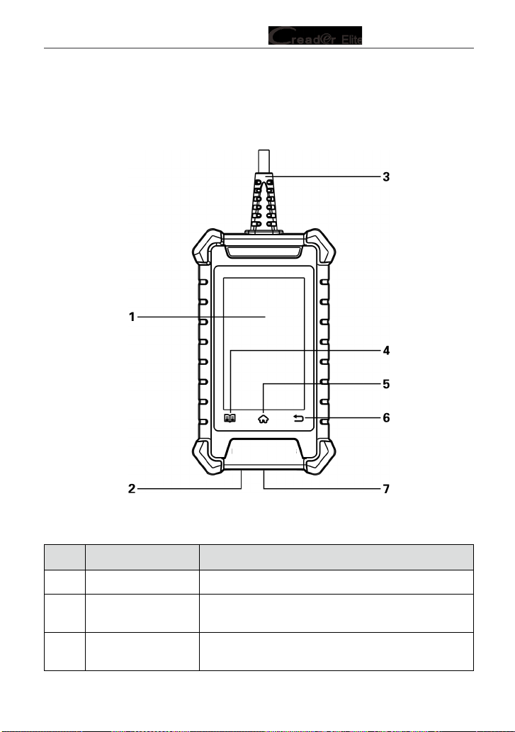
3. Product Descriptions
3.1 Components & Controls
Figure 3-1
No. Name Descriptions
1 Touch screen Indicates the test results.
2 Charging port
Connects it to the PC via the data cable to get
power.
3 Diagnostic cable
Connects it to the vehicle's DLC port to power up
the tool.

9
LAUNCH Series User Manual
4 Settings button Quick dial to the Settings module.
5
HOME button Press to the home (Job menu) screen.
6
BACK button
Exit the current program or return to the previous
screen.
7 Memory card slot
Current disabled and only reserved for future
use.
3.2 Technical Specications
• Screen: 4” touch screen with a resolution of 480*800
• CPU: 4-core 1.3GHz processor
• RAM: 1GB
• ROM: 16GB
• WiFi: 802.11b/g/n 2.4GHz
• USB: TYPE C
• OBD II input voltage range: 9~18V
• Power up via:
• DC 5V data cable or
• Diagnostic cable through connection to vehicle’s DLC
• Working temperature: -10 to 50°C (14 to 122 F°)
• Storage temperature: -20 to 70°C (-4 to 158 F°)
3.3 Accessories Checklist
For detailed accessory items, please consult from the local agency.
1. Creader Elite 300/302/305/310 tool
2. Data cable
3. User manual
4. Quick Start Guide

10
LAUNCH Series User Manual
4. Initial Use
4.1 Powering Up The Tool
There are two methods available for powering up the tool:
Via Data Cable: Plug one end of the included data cable into the charging port of
the tool, and the other end to the PC.
Via Diagnostic Cable: Insert the diagnostic cable into the vehicle’s DLC port.
When the tool is powered on, the screen will automatically light up.
4.2 Getting Started
If it is the first time you have used this tool, you need to make some system
settings.
1. Power on the tool. The screen displays a welcome page. Tap “Start” to go to
next step.
2. Choose the desired system language, and tap “Next”.
3. Choose the desired time zone, and tap “Next” to enter the WLAN setup
screen.
4. Slide the switch to ON, the system starts searching for all available wireless
LANs. Choose the desired WLAN access point / network,
Fig. 4-1
• If the network you chose is open, you can connect directly.
• If the selected network is encrypted, you have to enter the right security
11
LAUNCH Series User Manual
key (network password).
Note: If you choose “Ignore” in WLAN setup, it will go into the date setting
page. If the tool has been properly connected to the Internet, the system will
automatically obtain the correct network date and time and navigate to step 5.
5. After the network connection is done, tap “Next Step” to congure workshop
information. Input the required information, and tap “Next Step” to go to next
step.
Note: After you congured it, the system will append it on the report every time
a report is successfully generated.
6. Carefully read all terms and conditions of the user agreement, check the box
before the “Agree to all the above terms”, and tap “OK” finish the sign-up
process and navigate to Job Menu.
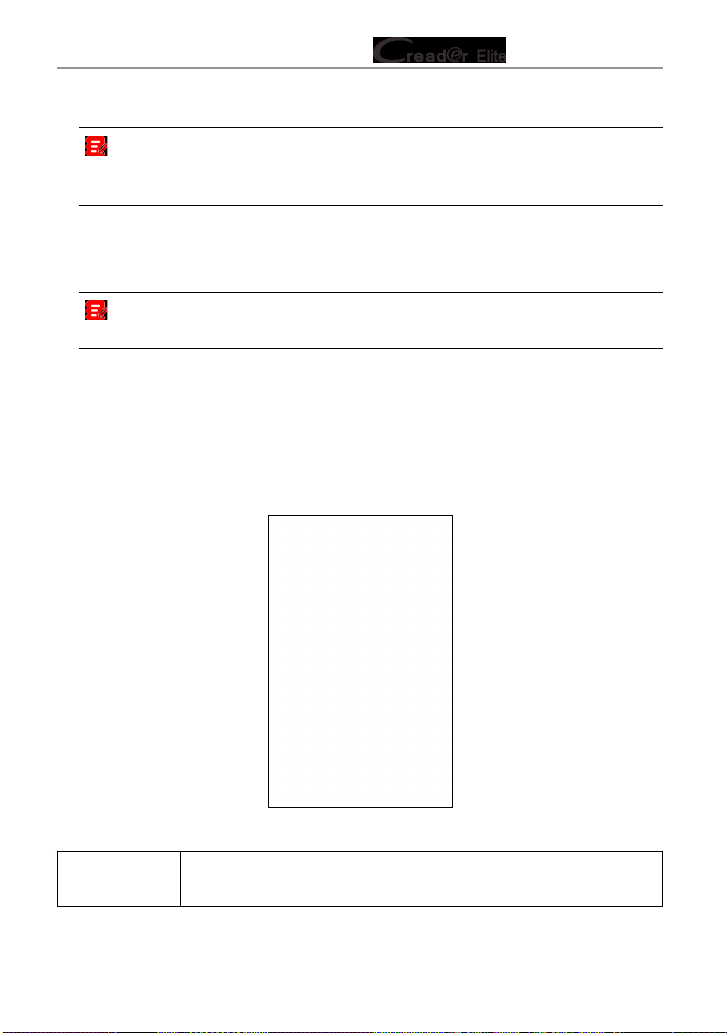
4.3 Job Menu
It mainly includes the following function modules.
Fig. 4-2
Diagnose
Configures the tool to operate as a professional diagnostic
tool.
12
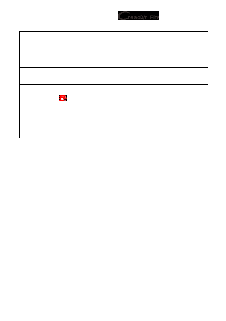
LAUNCH Series User Manual
OBD II
This option presents a quick way to check for DTCs, isolate
the cause of the illuminated Malfunction Indicator Lamp (MIL),
check monitor status prior to emissions certification testing,
verify repairs, and perform a number of other services that are
emission-related.
Reset
This function allows you to perform dierent kinds of common
special functions. Refer to Chapter 5.5 for details.
Upgrade
To update vehicle diagnostic software and APK.
Note: This function requires a stable network connection.
Mall
To subscribe extra vehicle diagnostic software or reset (special
function) software that are not included within the tool.
Settings
To manage data and make some system settings, including
Network setup, Workshop information and Brightness etc.
13
LAUNCH Series User Manual
5. Diagnose
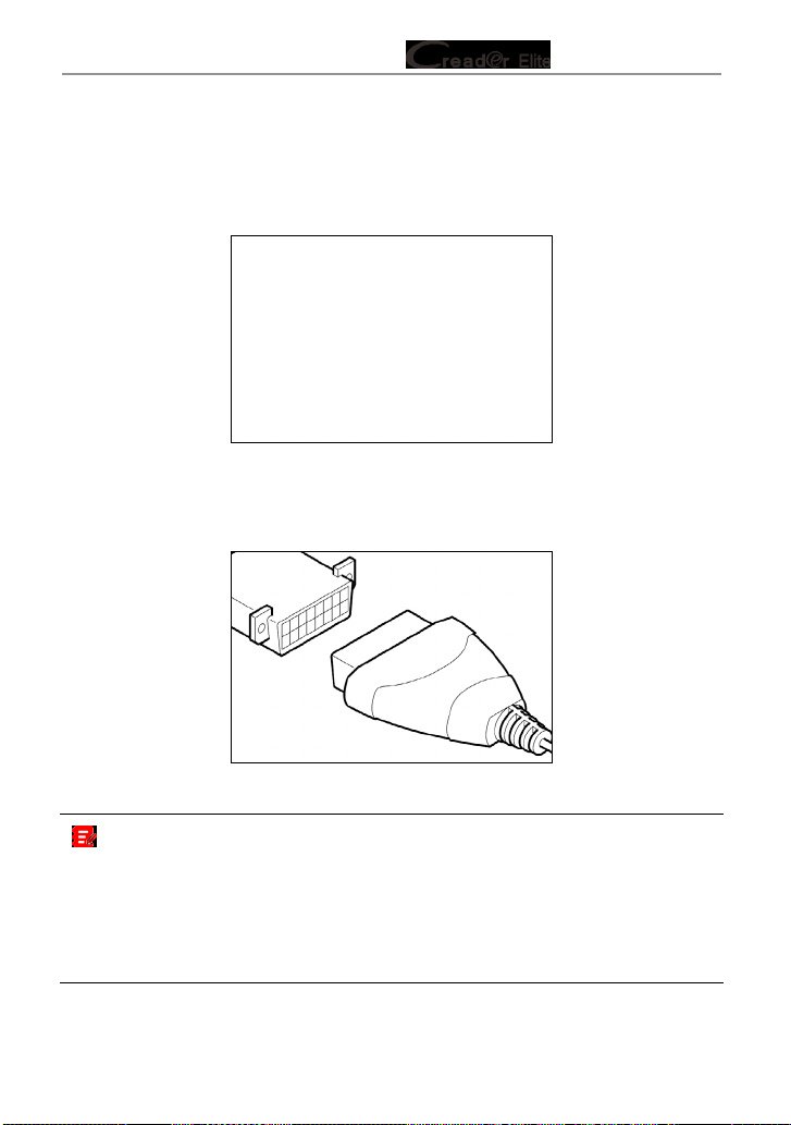
5.1 Connection
1. Turn the ignition o.
Figure 5-1
2. Locate vehicle’s DLC port. See Figure 2-2 for possible DLC location.
3. Plug the diagnostic cable into the vehicle’s DLC port.
Figure 5-2
Notes:
• A plastic DLC cover may be found for some vehicles and you need to remove it
before plugging the diagnostic cable.
• The cable connector is keyed and will only fit one way. If you have problems
connecting the cable connector to the DLC, rotate the connector 180
o
and try
again.
14
LAUNCH Series User Manual
5.2 System Diagnosing
This function is specially designed to diagnose electronic control systems of
single vehicle model.
The following vehicle systems are supported:
• ABS (Anti-lock Braking System)
• SRS (Supplemental Inatable Restraint System)
• Engine
5.2.1 Smart Diagnosis (Auto-Detect)
After connection, turn the ignition key on and the system enters auto-detect
mode
(
Note: Please make sure the “Automatic detection on connect” in “Settings” is
set as ON).
Note: To detect more and accurate VINs, a stable network connection is highly
recommended for this function.
CAUTION: Don’t connect or disconnect any test equipment with ignition on or
engine running.
A. Once the system successfully obtains the VIN (Vehicle Identication Number)
information of the currently identified vehicle, it will continue scanning the
vehicle systems. After the scanning is complete, a diagnostic report will be
automatically generated in the Settings -> Data -> Diagnostic Report.
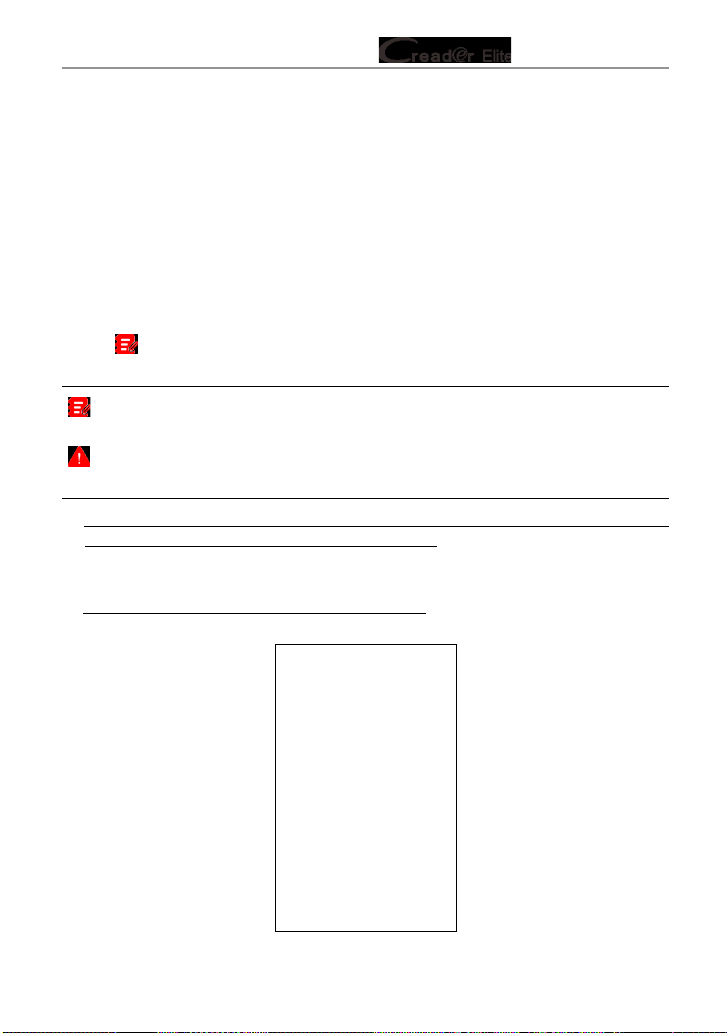
B. If the tool failed to access the VIN information, the following popup will appear
on the screen:
Fig. 5-3

15
LAUNCH Series User Manual
Input the VIN, and tap “OK”, the system will automatically identify the vehicle
model. If the vehicle VIN is successfully decoded, it will perform auto-
diagnosis until a diagnostic report is automatically output. Otherwise it will
enter manual diagnosis mode. For details on manual diagnosis, see Chapter
5.2.2.
Notes:
• The most recognizable location for this number is in the top left corner on the
vehicle’s dashboard. Other locations include the driver’s door or post, and the
rewall under the hood.
• In general, vehicle identification numbers are standardized - all contain 17
characters. VIN characters may be capital letters A through Z and numbers
1 through 0; however, the letters I, O and Q are never used in order to avoid
mistakes of misreading. No signs or spaces are allowed in the VIN.
5.2.2 Manual Diagnosis
If the tool can not obtain the VIN information, you can also perform vehicle
diagnosis manually. In this mode, you need to execute the menu-driven
command and then follow the on-screen instruction to proceed.
Fig. 5-4
Note: For vehicles manufactured by different vendors, it is possible that it has
dierent diagnostic menus. For details, please follow the instructions on the screen to
proceed.
16
LAUNCH Series User Manual
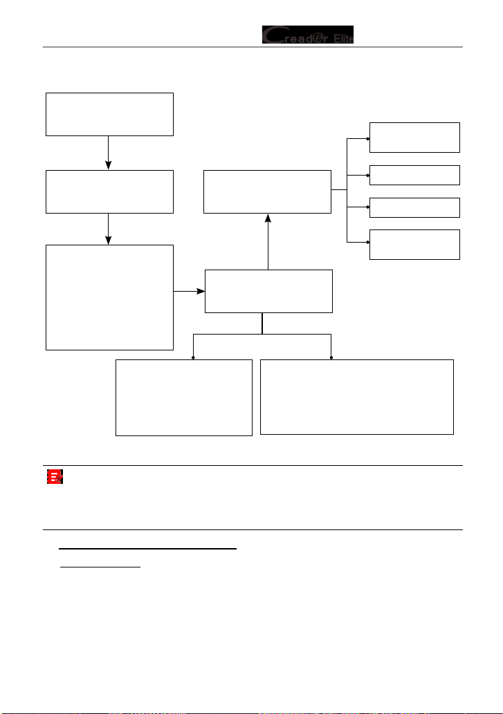
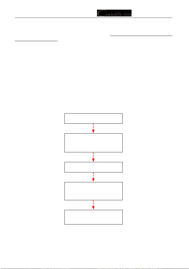
Refer to the owchart illustrated as below to diagnose a vehicle manually:
Select “Diagnose”
Automatic
(Note: This mode allows
your tool to scan the
vehicle test system
automatically)
Manual Select
(Note: In this case, you need to choose
the desired system manually. Just
follow the on-screen instructions to
proceed.)
Select test system
Select test function
Select Vehicle Model
(Note: For different
vehicles, vehicle make
selection may differ.
Generally, we can choose
a vehicle via make year.
But for BENZ, we need to
choose it via chassis.)
Select Vehicle
Manufacturer
Read version
information
Read fault code
Clear fault code
Read data
stream
Take Audi as an example to demonstrate how to diagnose a vehicle.
Note: Illustrations used in this manual are samples, the actual testing screen may
vary for each vehicle being tested. The following illustrations are based on the Audi
with full systems. Vehicle diagnostic software with full systems and full functions can
be purchased in the Mall.
1). Select diagnostic software version: Tap “Audi” to go to Step 2.
2). Select test item: Select the desired test item to proceed.

17
LAUNCH Series User Manual
Fig. 5-5
5.2.2.1 Health Report (Quick Test)
This function varies from vehicle to vehicle. It enables you to quickly access all
the electronic control units of the vehicle and generate a detailed report about
vehicle health.
Tap “Health Report”, the system starts scanning the ECUs. Once the scanning is
complete, the following screen will appear:
Fig. 5-6
In above gure, the tested system with fault code appears in red and the system
with OK displays in black (normally).
18
LAUNCH Series User Manual
On-Screen Buttons:
: Tap to display the details of DTCs existing in the current system. Tap to
hide it.
Enter: Tap to select other test functions. For detailed operations, refer to Chapter
5.2.2.2 “System Selection”.
Report: Tap to save the diagnostic result as a report.
Clear DTC: Tap to clear the existing diagnostic trouble codes.
5.2.2.2 System Selection
This option allows you manually select the test system and function step by step.
In Fig. 5-5, tap “System Selection”, and tap the desired system (take “ABS” for
example) to jump to the test function page.
Fig. 5-7
Note: Dierent vehicle has dierent diagnostic menus.
A. Version Information
This function is used to read the version information of system mode, vehicle
VIN, software and ECU.
B. Read Fault Code
This function displays the detailed information of DTC records retrieved from the
vehicle’s control system.
In Fig. 5-7, tap “Read Fault Code”, the screen will display the diagnostic result.
19
LAUNCH Series User Manual
Fig. 5-8
Note: Retrieving and using DTCs for troubleshooting vehicle operation is only
one part of an overall diagnostic strategy. Never replace a part based only on the DTC
denition. Each DTC has a set of testing procedures, instructions and ow charts that
must be followed to conrm the location of the problem. This information can be found
in the vehicle’s service manual.
On-Screen Buttons:
Help: Tap to view the help information.
Code Search: Tap it to search for more information about the current DTC online.
Report: To save the current data in text format. All diagnostic reports can be
accessed from Settings -> Data -> Diagnostic Report.
C. Clear Fault Code
After reading the retrieved codes from the vehicle and certain repairs have been
carried out, you can use this function to erase the codes from the vehicle. Before
performing this function, please be sure the vehicle’s ignition key is in the ON
position with the engine o.

20
LAUNCH Series User Manual
Notes:
1. If you plan to take the vehicle to a Service Center for repair, DO NOT erase the
codes from the vehicle’s computer. If data is erased, valuable information that might
help the technician troubleshoot the problem will also be erased.
2. Clearing DTCs does not x the problem(s) that caused the code(s) to be set. If proper
repairs to correct the problem that caused the code(s) to be set are not made, the
code(s) will appear again and the check engine light will illuminate as soon as the
problem that cause the DTC to set manifests itself.
D. Read Data Stream
This option retrieves and displays live data and parameters from the vehicle’s
ECU.
In Fig. 5-7, tap “Read Data Stream”, the system will display data stream items.
Fig. 5-9
On-Screen Buttons:
Select All: Tap it to select all items of the current page. To select certain data
stream item, just check the box before the item name.
Unselect: Tap it to deselect all data stream items.
OK: Tap it to conrm and jump to the next step.
After selecting the desired items, tap “OK” to enter the data stream reading
page.
21
LAUNCH Series User Manual
Fig. 5-10
Notes:
1. If the value of the data stream item is out of the range of the standard (reference)
value, the whole line will display in red. If it complies with the reference value, it
displays in blue (normal mode).
2. The indicator 1/X shown on the bottom of the screen stands for the current page /
total page number. Swipe the screen from the right / left to advance /return to the
next / previous page.
There are 3 types of display modes available for data viewing, allowing you to
view various types of parameters in the most suitable way.
• Value – this is the default mode which displays the parameters in texts and
shows in list format.
• Graph – displays the parameters in waveform graphs.
• Combine – this option is mostly used in graph merge status for data
comparison. In this case, dierent items are marked in dierent colors.
On-Screen Buttons:
: Tap it to view the waveform graph of the current data stream item.

22
LAUNCH Series User Manual
Fig. 5-11
Combine: Tap it, a pull-down list of the data stream items appears on the screen.
Select the necessary items (Max. 4 items can be selected at the same time) and
the screen will display the waveforms corresponding to these items immediately.
Fig. 5-12
Report: Tap to save the current data as a diagnostic report. All diagnostic reports
can be accessed from Settings -> Data -> Diagnostic Report. The tool logs the
Date of Report (the date and time at which the report was created) and assigns
a unique Report #.
Record: Tap to record and save Live Data. Recorded Live Data can serve as

23
LAUNCH Series User Manual
valuable information to help you in troubleshooting and diagnosing vehicle
problems. The saved le follows the naming rule: It begins with vehicle type, and
then the record starting time and ends with .x431 (To dierentiate between les,
please congure the accurate system time). All diagnostic records can be viewed
by tapping Settings -> Data -> Diagnostic Record.
5.3 OBDII Diagnosis
This option presents a quick way to check for DTCs, isolate the cause of the
illuminated Malfunction Indicator Lamp (MIL), check monitor status prior to
emissions certification testing, verify repairs, and perform a number of other
services that are emission-related.
On the Job menu, press [OBD II] to enter system, the screen will automatically
navigate to the Monitor status screen.
Tap [OK], the following function list appears.
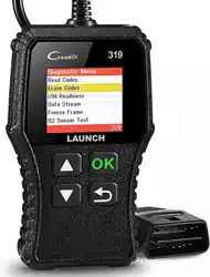
1. Read Codes
This option is used to identify which section of the emission control system has
malfunctioned.
2. Erase Codes
After reading the retrieved codes from the vehicle and certain repairs have been
carried out, you can use this function to erase the codes from the vehicle. Before
performing this function, please be sure the vehicle’s ignition key is in the ON
position with the engine o.
Notes:
• Before performing this function, make sure to retrieve and record the trouble codes.
• After clearing, you should retrieve trouble codes once more or turn ignition on
and retrieve codes again. If there are still some trouble codes in the system, please
troubleshoot the code using a factory diagnosis guide, then clear the code and
recheck.
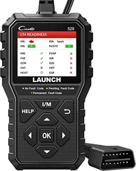
3. I/M Readiness
An important part of a vehicle’s OBD II system is the Readiness Monitors, which
are indicators used to find out if all of the emissions components have been
evaluated by the OBD II system. They are running periodic tests on specific
systems and components to ensure that they are performing within allowable
limits.
Currently, there are eleven OBD II Readiness Monitors (or I/M Monitors) dened

24
LAUNCH Series User Manual
by the U.S. Environmental Protection Agency (EPA). Not all monitors are
supported in every vehicles and the exact number of monitors in any vehicle
depends on the motor vehicle manufacturer’s emissions control strategy.
Continuous Monitors -- Some of the vehicle components or systems are
continuously tested by the vehicle’s OBD II system, while others are tested
only under specific vehicle operating conditions. The continuously monitored
components listed below are always ready:
1. Misre
2. Fuel System
3. Comprehensive Components (CCM)
Once the vehicle is running, the OBD II system is continuously checking the
above components, monitoring key engine sensors, watching for engine misre,
and monitoring fuel demands.
Non-Continuous Monitors -- Unlike the continuous monitors, many emissions
and engine system components require the vehicle to be operated under
specic conditions before the monitor is ready. These monitors are termed non-
continuous monitors and are listed below:
1) EGR System
2) O2 Sensors
3) Catalyst
4) Evaporative System
5) O2 Sensor Heater
6) Secondary air Injection
7) Heated Catalyst
8) A/C system
I/M refers to Inspection and Maintenance that is legislated by the Government
to meet federal clean-air standards. I/M Readiness indicates whether or not the
various emissions-related systems on the vehicle are operating properly and are
ready for Inspection and Maintenance testing.
The purpose of the I/M Readiness Monitor Status is to indicate which of the
vehicle’s Monitors have run and completed their diagnosis and testing, and
which ones have not yet run and completed testing and diagnosis of their
designated sections of the vehicle’s emissions system.
The I/M Readiness Monitor Status function also can be used (after repair of
a fault has been performed) to confirm that the repair has been performed
correctly, and / or to check for Monitor Run Status.

25
LAUNCH Series User Manual
This function can also be done by tapping [I/M Readiness] directly on the Job
Menu.
4. Data Stream
This option retrieves and displays live data and parameters from the vehicle’s
ECU.
5. View Freeze Frame
When an emission-related fault occurs, certain vehicle conditions are recorded
by the on-board computer. This information is referred to as freeze frame data.
Freeze Data is a snapshot of the operating conditions at the time of an emission-
related fault.
Note: If DTCs were erased, Freeze Data may not be stored in vehicle memory
depending on vehicle.
6. O2 sensor test
The results of O2 sensor test are not live values but instead the results of the
ECU’s last O2 sensor test. For live O2 sensor readings, refer to any of the live
sensor screens such as Graph Screen.
Not all test values are applicable to all vehicles. Therefore, the list generated
will vary depending on vehicle. In addition, not all vehicles support the Oxygen
Sensors screen.
7. On-board monitor test
This function can be utilized to read the results of on-board diagnostic monitoring
tests for specic components / systems.
8. EVAP System Test
The EVAP test function lets you initiate a leak test for the vehicle’s EVAP
system. The tool does not perform the leak test, but signals to vehicle’s on-board
computer to initiate the test. Before using the system test function, refer to the
vehicle’s service repair manual to determine the procedures necessary to stop
the test.
9. Vehicle Info
This option displays the vehicle information, such as VIN (Vehicle Identication
Number), CID (Calibration ID) and CVN (Calibration Verication Number).
5.4 History
Generally once a vehicle diagnosis is performed, the tool will record the every

26
LAUNCH Series User Manual
details of diagnostic session. The History function provides direct access to the
previously tested vehicles and users can resume from the last operation, without
the necessity of starting from scratch.
Tap “History” on the Diagnose main menu screen, all diagnostic records will be
listed on the screen in date sequence.
Fig. 5-13
• Tap certain vehicle model to view the details of the last diagnostic report.
• To delete certain diagnostic history, select it and then tap “Delete”. To delete
all historical records, tap “Select All” and then tap “Delete”.
• Tap “Quick access” to directly navigate to the function selection page of last
diagnostic operation. Choose the desired option to proceed.
5.5 Reset (Special Functions)
5.5.1 Download reset software
For initial use, user needs to select and download the desired reset software.
The available reset software depends on your product conguration.
For Creader Elite 300, no special function software packages are preset for
download and use. Go to “Mall” on the Job menu to purchase it if necessary.
For Creader Elite 302, total two selectable special function software is available
for download and use free of charge.
For Creader Elite 305, total ve selectable special function software is available
for download and use free of charge.
For Creader Elite 310, total 10 specic special function software is available for
27
LAUNCH Series User Manual
download and use free of charge.
To subscribe other special function software for Creader Elite 302/Creader Elite
305/Creader Elite 310, go to “Mall” on the Job menu to purchase it.
Tap “Reset”, all available reset software will be listed on the screen. Select the
desired reset software and tap “OK”, the system will navigate to the update
center to download.
5.5.2 How to perform reset procedures?
There are two methods to reset service lamp: Manual Reset or Auto Reset.
Auto Reset follows the principle of sending command from the tool to vehicle’s
ECU to do resetting. While using Manual Reset, users just follow the on-screen
instructions to select appropriate execution options, enter correct data or values,
and perform necessary actions, the system will guide you through the complete
performance for various service operations.
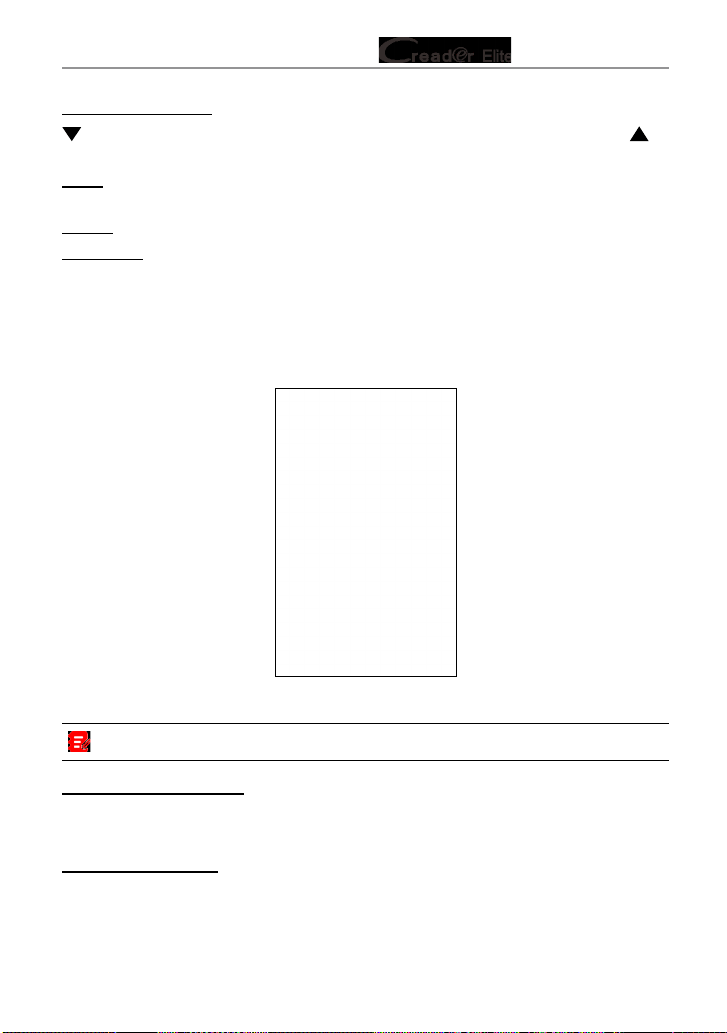
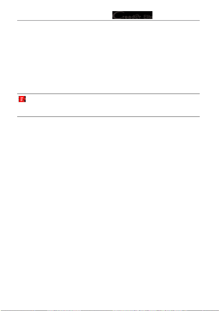
Follow the owchart shown as below to perform resetting.
Select "Reset"
Choose the desired service
function (e.g. oil lamp reset
etc.)
Select the desired car brand
Select the reset mode (The
available mode varies from
vehicle to vehicle)
Follow the on-screen
instructions to proceed

28
LAUNCH Series User Manual
6. Upgrade
This function allows you to update the diagnostic app and software. All software
is updated periodically.
It is recommended to check regularly for updates and install the latest software
version for the best service, functions and experience.
Note: Make sure the Wi-Fi connection is strong and stable while updating.
Tap “Upgrade” on the Job menu to enter the update center.
Fig. 6-1
By default, all diagnostic software is selected.
To deselect certain software, tap “Unselect”, and then check the box next to
vehicle model.
Tap “Update” to start downloading. It may take several minutes to nish, please
be patient.
Once download is nished, the software packages will be installed automatically.
29
LAUNCH Series User Manual
7. Mall
This function allows you to subscribe other vehicle diagnostic software and reset
software that are not pre-installed on the tool.
All diagnostic software in the mall covers full systems and full functions
(excluding online programming and coding etc). Dierent vehicle software is
tagged with dierent price.
Tap “Mall” to open the online software mall. Select the target software and follow
the on-screen instructions to nish the transaction.
Note: The software service belongs to the virtual goods. It becomes immediately
eective from the date of the successful transaction and it does not accept the refund.
When making payment, please double check the order information.
The subscribed software can be free to use for one year. After it expires, it will
become disabled and user needs to renew the subscription to activate it.
30
LAUNCH Series User Manual
8. Settings
8.1 Units of measurement
It is designed to set the measurement unit. Metric System and English System
are available.
8.2 Automatic detection on connect
This option enables you to determine whether to start an automatic VIN detection
once the tool is properly connected to the vehicle’s DLC.
8.3 Brightness
This item allows you to set the screen brightness.
Note: Reducing the brightness of the screen is helpful to conserve the power of the
tool.
8.4 Sound
This option lets you adjust the volume and other sound settings.
8.5 Network
Note: Once WLAN is set as ON, the tool will consume more power. While it keeps
unused, please set it o to save power. While WLAN keeps unused, please turn it o
to conserve battery power.
The tool has built-in WLAN module that can be used to get online. Once you’re
online, you can register your tool and update diagnostic software & APK.
Slide the switch to ON, the system starts searching for all available wireless
LANs. Choose the desired WLAN access point / network to connect.
8.6 Time Zone
This option allows you to set the time zone.
8.7 Language
The tool supports multiple languages. You can use this option to change the
system language to the target language.
31
LAUNCH Series User Manual
8.8 Workshop information
This option allows you to add a personalized tag on the diagnostic reports.
Note: After you congured it, the system will append it on the report every time a
report is successfully generated.
8.9 Recovery
Use this item to reset this tool to the default factory setting.
Warning: Resetting may cause data loss. Before doing so, please be careful to
perform this operation.
8.10 Clean Up
This option allows user to clear some cache files and free up some storage
space. After clearn up, the tool will reboot automatically.
8.11 Screen Capture
When set as ON, a oating screenshot icon will appear on the screen. Tap it to
capture the current screen. All screenshots are saved under Settings -> Data ->
Image.
8.12 About
This option displays the hardware configuration information of the tool and
license agreement.
8.13 Data
8.13.1 Diagnostic Record
If a user records the running parameters or waveform graphs while reading data
stream, it will be saved as diagnostic records and appear under this tab.
Tap “Diagnostic Record” to enter and select the desired data stream items, and
tap “OK” to jump to the playback page.
On-Screen Buttons:
Graph – displays the parameters in waveform graphs.
Combine – this option is mostly used in graph merge status for data comparison.
In this case, dierent items are marked in dierent colors.

32
LAUNCH Series User Manual
Value – this is the default mode which displays the parameters in texts and
shows in list format.
Frame Playback – plays back the recorded data stream items frame by frame.
Once it is in frame playback mode, this button changes into “Auto Playback”.
8.13.2 Diagnostic Report
This module stores all diagnostic reports generated in process of vehicle
diagnosis.
All the diagnostic reports are sorted by Date and Make. If there are too many
reports stored, tap
(Search) to lter and quickly locate it.
Fig. 7-1
• To select a certain report, just check the box at the right lower corner of the
report. To select all reports, tap “Select All”. To deselect all, tap “Unselect”.
• Tap it to view its details.
• Select the desired report and then tap “Delete” to delete it.
8.13.3 DTC Library
This option enables you to retrieve the detailed description of certain DTC from
the local DTC database.

33
LAUNCH Series User Manual
Fig. 7-2
Swipe the screen upwards / downwards to alter the value, then press [OK]
button, the screen will display denition of the DTC.
8.13.4 DLC (Data Link Connector) Location
This option helps you to nd the location of the vehicle’s DLC.
8.13.5 Image
This option allows you to view and manage all screenshots.
8.13.6 Feedback
This item allows you to feedback your diagnostic problems to us for analysis and
troubleshooting.
Tap “Feedback”, the following 3 options will be displayed on the screen.
A. Feedback
Tap a tested vehicle model to enter the feedback screen.
1) Tap “Choose File” to open the target folder and choose the desired diagnostic
logs.
2) Choose the failure type and ll in the detailed failure description in the blank
text box and telephone or email address. After inputting, tap “Submit Result”
to send it to us.
B. History
Tap it to view all diagnostic feedback records. Different process states are

34
LAUNCH Series User Manual
marked with dierent colors.
C. Oine list
Tap it to display all diagnostic feedback logs which have not been submitted
successfully due to network failure. Once the tool gets a stable network signal, it
will be uploaded to the remote server automatically.
8.13.7 Firmware Fix
Use this item to upgrade and x diagnostic rmware. During xing, please do not
cut power or switch to other interfaces.
8.13.8 User Manual
The user manual is integrated on the tool for your easier check and reference.

35
LAUNCH Series User Manual
9. FAQ
Here we list some frequently asked questions and answers related to this tool.
1
System halts when reading data stream. What is the reason?
It may be caused by a slackened connector. Please turn this tool off, firmly
connect the connector, and switch it on again.
2
Screen of the tool ashes at engine ignition start.
Caused by electromagnetic disturbing, and this is normal phenomenon.
3
There is no response when communicating with on-board computer.
Please confirm the proper voltage of power supply and check if the throttle
has been closed, the transmission is in the neutral position, and the water is in
proper temperature.
4
What to do if the system fails to start auto VIN detection?
Please check the following possible reasons:
• Whether the tool is properly connected to the vehicle’s DLC port.
• Whether the “Automatic detection on Connect” switch is OFF. If yes, slide it to
ON.
5
Why are there so many fault codes?
Usually, it’s caused by poor connection or fault circuit grounding.
6
How to upgrade the system?
1. Switch the tool on and ensure a stable internet connection.
2. Tap “Settings” on the Job Menu, select “About” -> “Version”, and tap “Detect
the System Version” to enter the system upgrading page.
3. Follow the on-screen instructions step by step to finish the process. It may
take several minutes depending on the internet speed, please be patient. After
upgrade is successfully nished, the tool will automatically restart and enters
the Job menu.

36
LAUNCH Series User Manual
If you have any questions on the operation of the unit, please contact customer
service number: +86-755-84557891.
Statement:
We reserve the rights to make any change to product designs and specications without
notice. The actual object may differ a little from the descriptions in the manual in
physical appearance, color and configuration. We have tried our best to make the
descriptions and illustrations in the manual as accurate as possible, and defects are
inevitable, if you have any question, please contact local dealer or after-sale service
center, we shall not bear any responsibility arising from misunderstandings.