
Loading ...
Loading ...
Loading ...
© Xiamen RGBlink Science & Technology Co., Ltd.
Ph: +86 592 5771197 | support@rgblink.com | www.rgblink.com
9
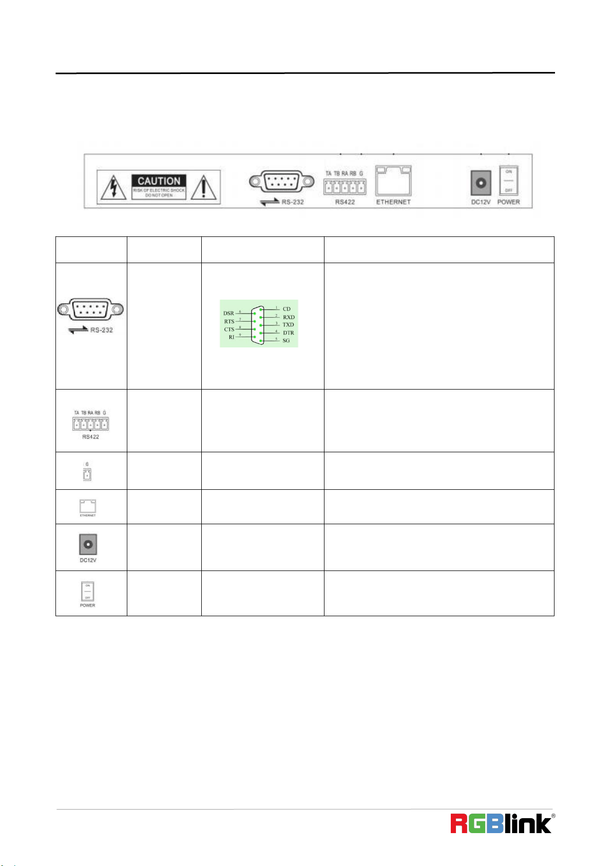
2.1.4 Terminal Description of Back Panel Interfaces
Back Panel Details: RS422, RS232, DC-12V, Ethernet, Power Switch
Number
Label
Physical interface
Description
RS 232
Pin 1 : Received Line Signal Detector
Pin 2 : Received Data
Pin 3 : Transmit Data
Pin 4 : Data Terminal Ready
Pin 5 : Signal Ground
Pin 6 : Data Set Ready
Pin 7 : Request To Send
Pin 8 : Clear To Send
Pin 9 : Ring Indicator
RS422
Control Output
(TA, TB, RA, RB)
Connect to RS422 bus of the camera: TA to
camera RA; TB to camera RB; RA to camera TA; RB
to camera TB.
Ground
Control line ground (G)
Control signal Line ground
ETHERNET
Ethernet port
Network connection
DC- 12V
Power input
DC 12V Power input
POWER
Power switch
Power on/ off
2.2 Local Settings (SETUP)
2.2.1 Basic Settings
Move the joystick up and down to switch 1 to 2, and 2 to 3 settings; Move the joystick left and right to switch on
and off the button sound prompts, confirm with ENTER button.
(1) Network Type: dynamic and static
(2) Button sound prompt: on and off
Loading ...
Loading ...
Loading ...