Loading ...
Loading ...
Loading ...
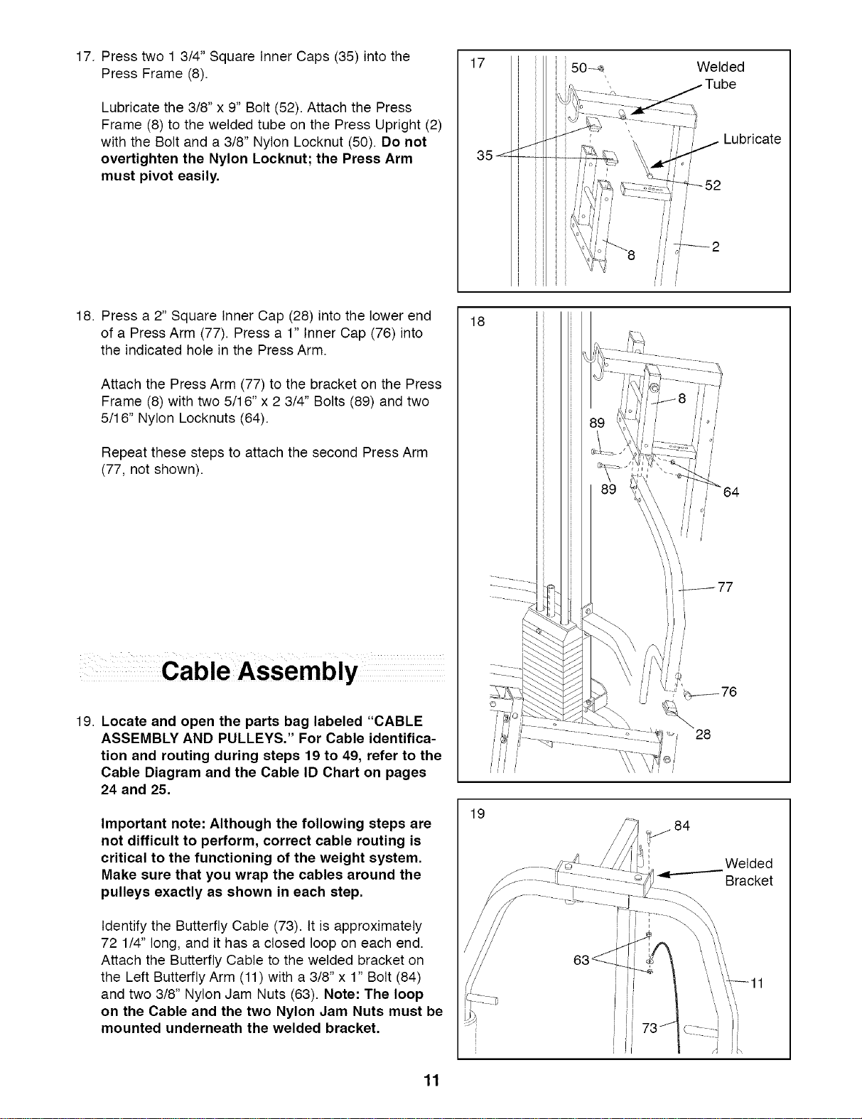
17. Press two 1 3/4" Square Inner Caps (35) into the
Press Frame (8).
Lubricate the 3/8" x 9" Bolt (52). Attach the Press
Frame (8) to the welded tube on the Press Upright (2)
with the Bolt and a 3/8" Nylon Locknut (50). Do not
overtighten the Nylon Locknut; the Press Arm
must pivot easily.
18. Press a 2" Square Inner Cap (28) into the lower end
of a Press Arm (77). Press a 1" Inner Cap (76) into
the indicated hole in the Press Arm.
Attach the Press Arm (77) to the bracket on the Press
Frame (8) with two 5/16" x 2 3/4" Bolts (89) and two
5/16" Nylon Locknuts (64).
Repeat these steps to attach the second Press Arm
(77, not shown).
19. Locate and open the parts bag labeled "CABLE
ASSEMBLY AND PULLEYS." For Cable identifica-
tion and routing during steps 19 to 49, refer to the
Cable Diagram and the Cable ID Chart on pages
24 and 25.
Important note: Although the following steps are
not difficult to perform, correct cable routing is
critical to the functioning of the weight system.
Make sure that you wrap the cables around the
pulleys exactly as shown in each step.
Identify the Butterfly Cable (73). It is approximately
72 1/4" long, and it has a closed loop on each end.
Attach the Butterfly Cable to the welded bracket on
the Left Butterfly Arm (11) with a 3/8" x 1" Bolt (84)
and two 3/8" Nylon Jam Nuts (63). Note: The loop
on the Cable and the two Nylon Jam Nuts must be
mounted underneath the welded bracket.
17
18
19
ii50
Welded
Lubricate
o/
_-_52
28
_ 84
Welded
Bracket
\ \,\
11
Loading ...
Loading ...
Loading ...