Patent Pending
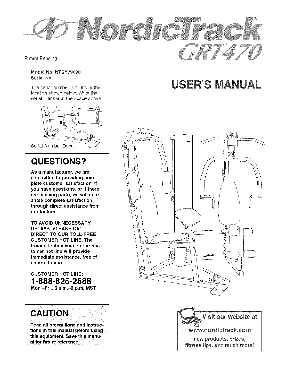
Model No. NTSY73690
Serial No.
The seda! number is found in the
location shown below. Write the
serial number in the space above.
Serial Number Decal
QUESTIONS?
As a manufacturer, we are
committed to providing com-
plete customer satisfaction. If
you have questions, or if there
are missing parts, we will guar-
antee complete satisfaction
through direct assistance from
our factory.
TO AVOID UNNECESSARY
DELAYS, PLEASE CALL
DIRECT TO OUR TOLL-FREE
CUSTOMER HOT LINE. The
trained technicians on our cus-
tomer hot line will provide
immediate assistance, free of
charge to you.
CUSTOMER HOT LINE:
1-888-825-2588
Mon.-Fri., 6 a.m.-6 p.m. MST
CAUTION
Read all precautions and instruc-
tions in this manual before using
this equipment. Save this manu-
al for future reference.
®
_-Visit cur website at
www.nordictraek.com
new products, prizes,
fitness tips, and much more!
Important Precautions ................................................................... 2
Before You Begin ...................................................................... 3
Assembly ............................................................................ 4
Weight Resistance Chart ................................................................ 23
Cable Diagrams ...................................................................... 24
Adjustment .......................................................................... 26
Trouble-shooting and Maintenance ........................................................ 27
Ordering Replacement Parts ...................................................... Back Cover
Limited Warranty ............................................................... Back Cover
Note: A Part List/Exploded Drawing and a Part Identification Chart are attached in the center of this manual.
WARNING: To reduce the risk of serious injury, read the following important precautions
before using the home gym.
1. It is the responsibility of the owner to ensure 10. Always wear athletic shoes for foot protec-
that all users of the home gym are adequately tion when exercising.
informed of all precautions.
11. Never release the press arms, butterfly arms.
2. Read all instructions in this manual and in leg lever, lat bar. row bar, or ab strap while
the accompanying literature before using the weights are raised. The weights will fall with
home gym. great force.
3. The home gym is intended for home use only. 12. If you feel pain or dizziness while exercising,
Do not use the home gym in a commercial.
rental or institutional setting.
4. Use the home gym only on a level surface.
Cover the floor or carpet beneath the home
gym for protection.
5. Inspect and tighten all parts often. Replace
any worn parts immediately.
6. Make sure that the cables remain on the pul-
leys at all times. If the cables bind while you
are exercising, stop immediately and make
sure the cables are on all of the pulleys.
7. Always stand on the foot plate when perform-
ing an exercise that could cause the home
gym to tip.
8. Keep hands and feet away from moving parts.
9. Keep children under the age of 12 and pets
away from the home gym at all times.
stop immediately and begin cooling down.
13. Always disconnect the lot bar. row bar. or ab
strap from the home qym when performinq
exercises that do not use these attachments.
14. The decal shown
at the right has
been attached to
the home gym in
the two locations
shown on page 3.
If a decal is miss-
ing or illegible,
please call toll-free
1-888-825-2588 to
order a free
replacement deca I.
Apply the decal in
the location
shown.
•Misuseofthisoroduc_
mayresumtnserious
Injury.
•Readuser'smanual
andfoHHowallwarnings
andoperatinginstruc-
tionsuriortouse.
oDonotaHIowchildren
onoraroundmachine,
oReoHacelabeHif
damaged HHegibHe,or
removed.
WARNING: Before beginning this or any exercise program, consult your physician. Th is is especially
important for persons over the age of 35 or persons with pre-existing health problems. Read all
instructions before using. ICON assumes no responsibility for personal injury or property damage
sustained by or through the use of this product.
2
Thank you for selecting the innovative and versatile
NordicTrack '_;GRT470 home gym. The NordicTrack
GRT470 offers a large selection of weight stations
designed to develop every major muscle group of the
body. Whether your goal is to tone your body, build
dramatic muscle size and strength, or improve your
cardiovascular system, the NordicTrack GRT470 will
help you to achieve the results you want.
For your benefit, read this manual carefully before
using the Nordictrack GRT470, If you have addition-
al questions, please call our Customer Service
Department toll-free at 1-888-825-2588, Monday
through Friday, 6 a.m. until 6 p.m. Mountain Time
(excluding holidays). To help us assist you, please
note the product model number and serial number
before calling. The model number is NTSY73690. The
serial number can be found on a decal attached to the
home gym (see the front cover of this manual).
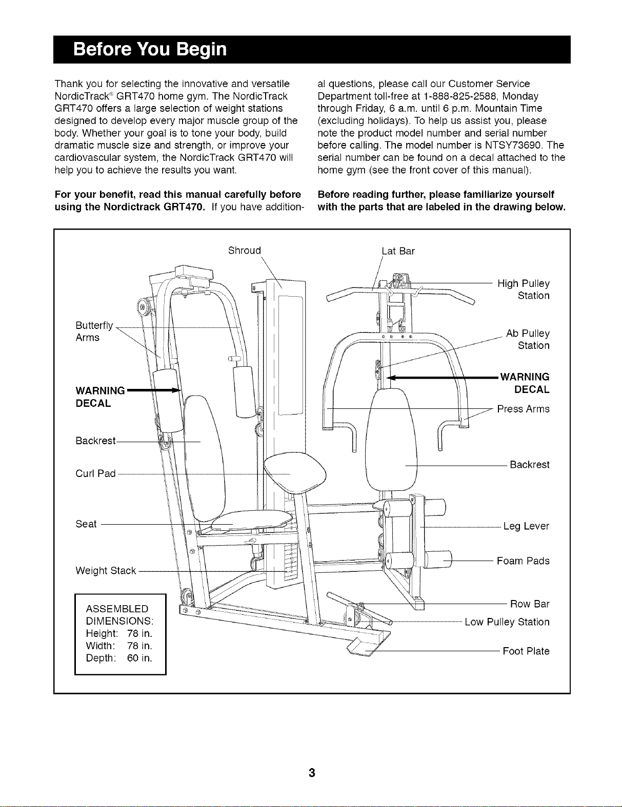
Before reading further, please familiarize yourself
with the parts that are labeled in the drawing below,
Shroud Lat Bar
Arms
DECAL
Backrest--
Curl Pad
High Pulley
Station
Ab Pulley
Station
DECAL
Press Arms
Backrest
Seat
Weight Stack
Leg Lever
Foam Pads
ASSEMBLED
DIMENSIONS:
Height: 78 in.
Width: 78 in.
Depth: 60 in.
Row Bar
Low Pulley Station
Foot Plate
3
Make Assembly Easier for Yourself!
Everything in this manual isdesigned to
ensure that the home gym can be assembled
successfully by anyone. Before beginning
assembly, make sure to read the informa-
tion on this page; this brief introduction
will save you much more time than it takes
to read it!
Assembly Requires Two Persons
For your convenience and safety, assemble the
home gym with the help of another person.
Set Aside Enough Time
Due to the many features of the home gym, the
assembly process will require about six hours. By
setting aside plenty of time and by deciding to
make the task enjoyable, assembly will go smoothly.
You may want to assemble the home gym over a
couple of evenings.
Select a Location for the Home Gym
Because of its weight and size, the home gym
should be assembled in the location where it will be
used. Make sure that there is enough room to walk
around the home gym as you assemble it.
How to Unpack the Box
To make assembly as easy as possible, we have
divided the assembly process into four stages. The
parts needed for each stage are found in individual
bags. Important: Wait until you begin each stage
to open the part bag for that stage. Place all
parts of the home gym in a cleared area and
remove the packing materials. Do not dispose of
the packing materials until assembly is completed.
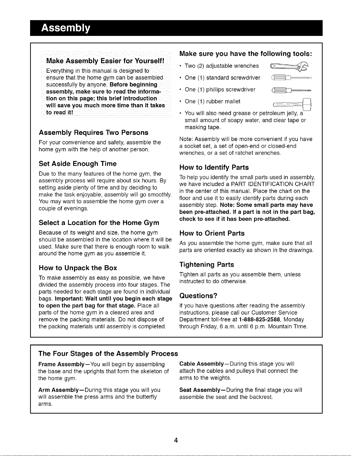
Make sure you have the following tools:
• Two (2) adjustable wrenches
• One (1) standard screwdriver
• One (1) phillips screwdriver
• One (1) rubber mallet
• You will also need grease or petroleum jelly, a
small amount of soapy water, and clear tape or
masking tape.
Note: Assembly will be more convenient if you have
a socket set, a set of open-end or closed-end
wrenches, or a set of ratchet wrenches.
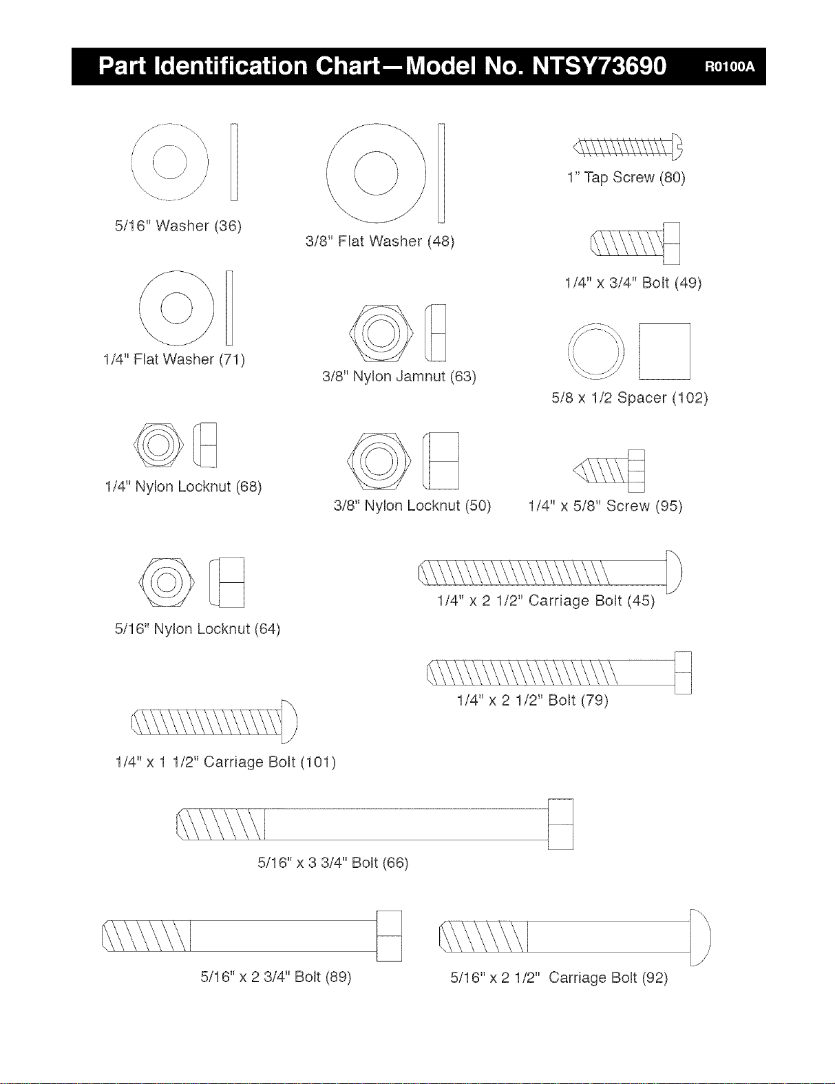
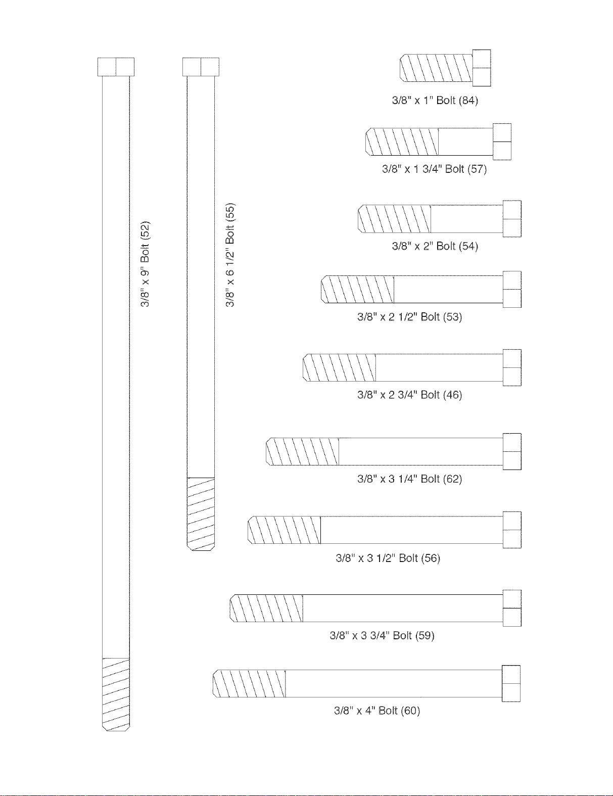
How to Identify Parts
To help you identify the small parts used in assembly,
we have included a PART IDENTIFICATION CHART
in the center of this manual. Place the chart on the
floor and use it to easily identify parts during each
assembly step. Note: Some small parts may have
been pre-attached. If a part is not in the part bag,
check to see if it has been pre-attached,
How to Orient Parts
As you assemble the home gym, make sure that all
parts are oriented exactly as shown in the drawings.
Tightening Parts
Tighten all parts as you assemble them, unless
instructed to do otherwise.
Questions?
If you have questions after reading the assembly
instructions, please call our Customer Service
Department toll-free at 1-888-825-2588, Monday
through Friday, 6 a.m. until 6 p.m. Mountain Time.
The Four Stages of the Assembly Process
Frame Assembly--You will begin by assembling Cable Assembly--During this stage you will
the base and the uprights that form the skeleton of attach the cables and pulleys that connect the
the home gym. arms to the weights.
Arm Assembly--During this stage you will you
will assemble the press arms and the butterfly
arms.
Seat Assembly--During the final stage you will
assemble the seat and the backrest.
4
1a ,i_ 28
1,
2,
Before you begin this step, make sure that
you have read all of the information on page
4. This introduction wi!l save you much more
time than it takes to read it!
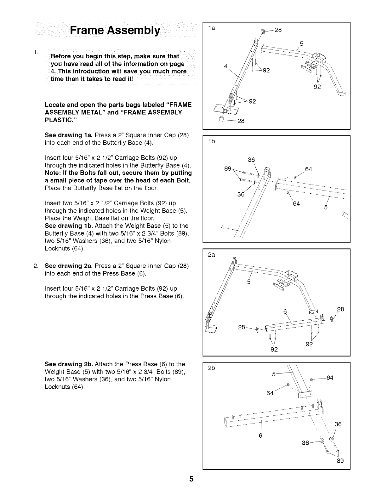
Locate and open the parts bags labeled "FRAME
ASSEMBLY METAL" and "FRAME ASSEMBLY
PLASTIC."
See drawing la. Press a 2" Square Inner Cap (28)
into each end of the Butterfly Base (4).
Insert four 5/16"x 2 1/2" Carriage Bolts (92) up
through the indicated holes in the Butterfly Base (4).
Note: If the Bolts fall out, secure them by putting
a small piece of tape over the head of each Bolt.
Place the Butterfly Base flat on the floor.
Insert two 5/16" x 2 1/2" Carriage Bolts (92) up
through the indicated holes in the Weight Base (5).
Place the Weight Base flat on the floor.
See drawing lb, Attach the Weight Base (5) to the
Butterfly Base (4) with two 5/16" x 2 3/4" Bolts (89),
two 5/16" Washers (36), and two 5/16" Nylon
Locknuts (64).
See drawing 2a. Press a 2" Square Inner Cap (28)
into each end of the Press Base (6).
Insert four 5/16" x 2 1/2" Carriage Bolts (92) up
through the indicated holes in the Press Base (6).
See drawing 2b. Attach the Press Base (6) to the
Weight Base (5) with two 5/16" x 2 3/4" Bolts (89),
two 5/16" Washers (36), and two 5/16" Nylon
Locknuts (64).
4
92
lb
36
64
36
64
2a
92
92
2b
oi
28
36
89
8,
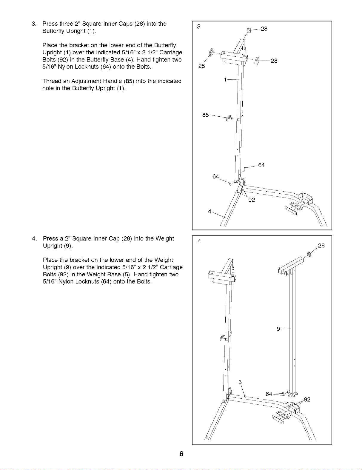
Press three 2" Square Inner Caps (28) into the
Butterfly Upright (1).
Place the bracket on the lower end of the Butterfly
Upright (1) over the indicated 5/16" x 2 1/2" Carriage
Bolts (92) in the Butterfly Base (4). Hand tighten two
5/16" Nylon Locknuts (64) onto the Bolts.
Thread an Adjustment Handle (85) into the indicated
hole in the Butterfly Upright (1).
28
64
92
28
4,
Press a 2" Square Inner Cap (28) into the Weight
Upright (9).
Place the bracket on the lower end of the Weight
Upright (9) over the indicated 5/16" x 2 1/2" Carriage
Bolts (92) in the Weight Base (5). Hand tighten two
5/16" Nylon Locknuts (64) onto the Bolts.
28
6
5. 5
8.
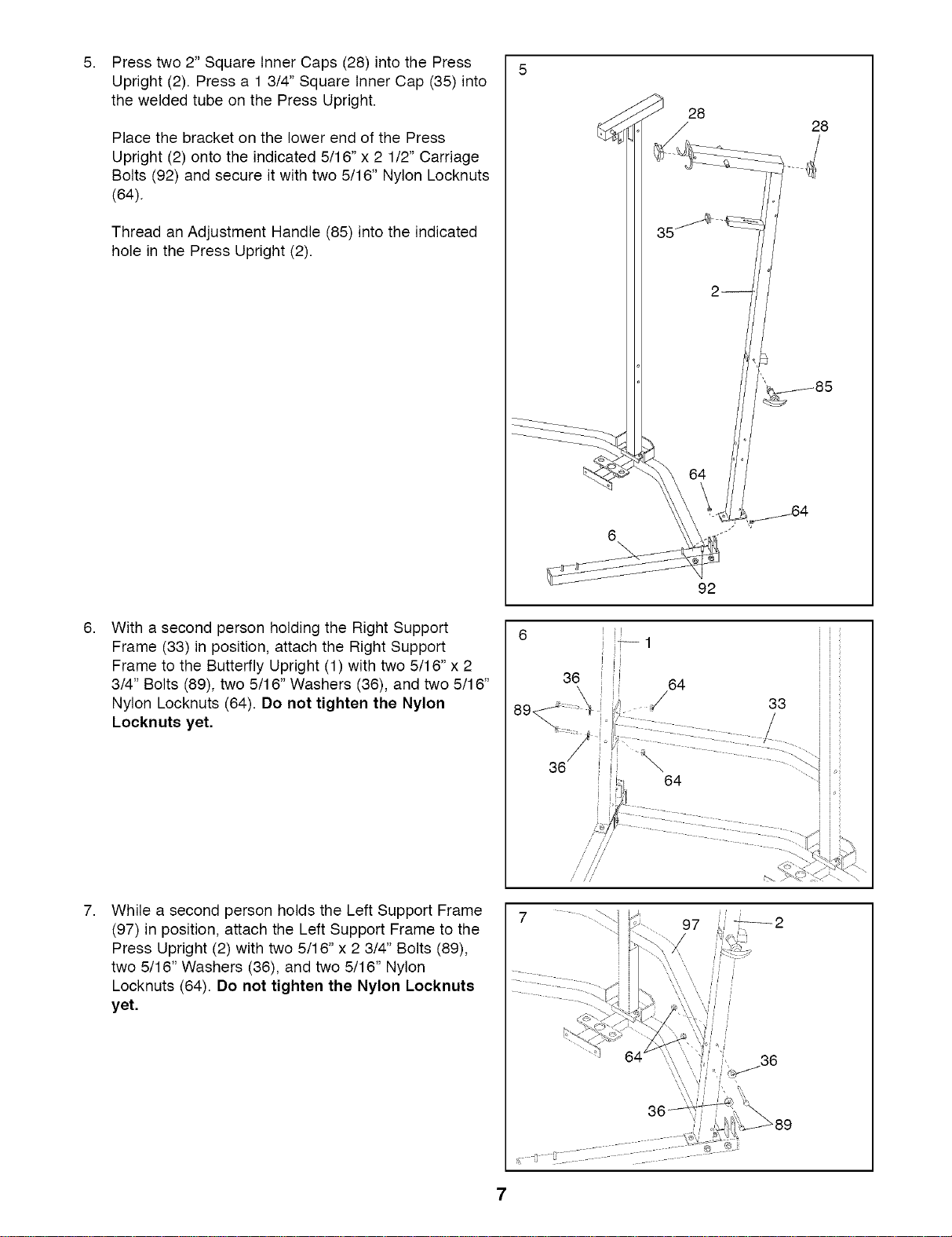
Press two 2" Square Inner Caps (28) into the Press
Upright (2). Press a 1 3/4" Square Inner Cap (35) into
the welded tube on the Press Upright.
Place the bracket on the lower end of the Press
Upright (2) onto the indicated 5/16"x 2 1/2" Carriage
Bolts (92) and secure it with two 5/16" Nylon Locknuts
(64).
Thread an Adjustment Handle (85) into the indicated
hole in the Press Upright (2).
With a second person holding the Right Support
Frame (33) in position, attach the Right Support
Frame to the Butterfly Upright (1) with two 5/16"x 2
3/4" Bolts (89), two 5/16" Washers (36), and two 5/16"
Nylon Locknuts (64). Do not tighten the Nylon
Locknuts yet.
28
28
35
92
i-- 1
36 64
36
7.
While a second person holds the Left Support Frame
(97) in position, attach the Left Support Frame to the
Press Upright (2) with two 5/16" x 2 3/4" Bolts (89),
two 5/16" Washers (36), and two 5/16" Nylon
Locknuts (64). Do not tighten the Nylon Locknuts
yet,
97
8,
9,
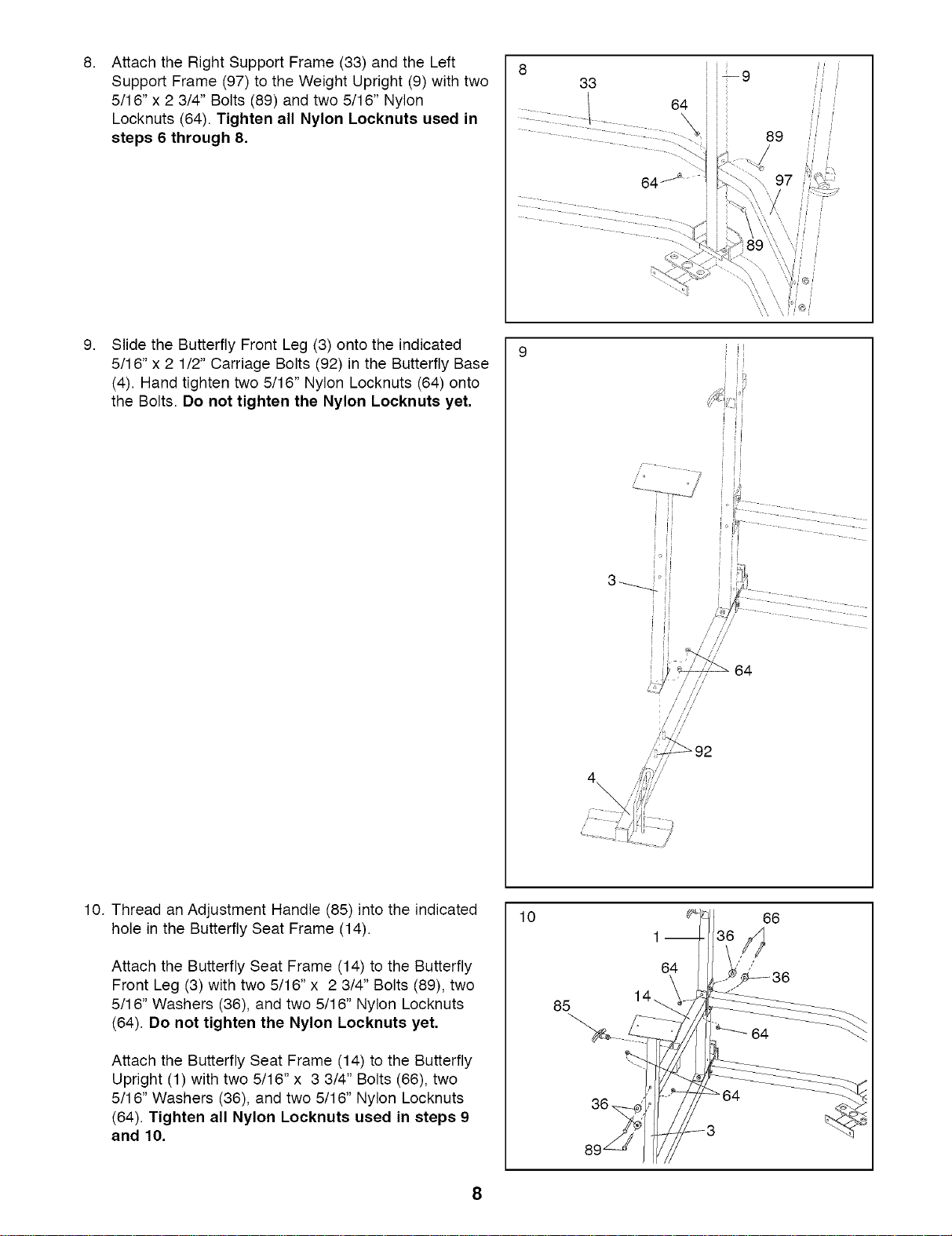
Attach the Right Support Frame (33) and the Left
Support Frame (97) to the Weight Upright (9) with two
5/16" x 2 3/4" Bolts (89) and two 5/16" Nylon
Locknuts (64) Tighten all Nylon Locknuts used in
steps 6 through 8.
Slide the Butterfly Front Leg (3) onto the indicated
5/16"x 2 1/2" Carriage Bolts (92) in the Butterfly Base
(4) Hand tighten two 5/16" Nylon Locknuts (64) onto
the Bolts. Do not tighten the Nylon Locknuts yet.
8 33 i i_9
1 64
10. Thread an Adjustment Handle (85) into the indicated
hole in the Butterfly Seat Frame (14)
Attach the Butterfly Seat Frame (14) to the Butterfly
Front Leg (3) with two 5/16" x 2 3/4" Bolts (89), two
5/16" Washers (36), and two 5/16" Nylon Locknuts
(64). Do not tighten the Nylon Locknuts yet.
Attach the Butterfly Seat Frame (14) to the Butterfly
Upright (1) with two 5/16" x 3 3/4" Bolts (66), two
5/16" Washers (36), and two 5/16" Nylon Locknuts
(64). Tighten all Nylon Locknuts used in steps 9
and 10.
10
85
36
1 m
64
/
66
8
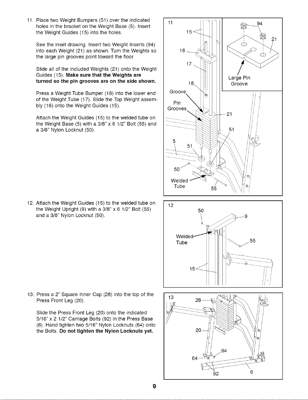
11. Place two Weight Bumpers (51) over the indicated
holes in the bracket on the Weight Base (5). Insert
the Weight Guides (15) into the holes.
See the inset drawing. Insert two Weight Inserts (94)
into each Weight (21) as shown. Turn the Weights so
the large pin grooves point toward the floor.
Slide all of the included Weights (21) onto the Weight
Guides (15). Make sure that the Weights are
turned so the pin grooves are on the side shown,
Press a Weight Tube Bumper (18) into the lower end
of the Weight Tube (17). Slide the Top Weight assem-
bly (16) onto the Weight Guides (15).
Attach the Weight Guides (15) to the welded tube on
the Weight Base (5) with a 3/8" x 6 1/2" Bolt (55) and
a 3/8" Nylon Locknut (50).
11
18\
Groove
Pin
Grooves
Welded
Tube
55
Large Pin
Groove
21
12. Attach the Weight Guides (15) to the welded tube on
the Weight Upright (9) with a 3/8" x 6 1/2" Bolt (55)
and a 3/8" Nylon Locknut (50).
12
Tube
50
1
55
13. Press a 2" Square Inner Cap (28) into the top of the
Press Front Leg (20).
Slide the Press Front Leg (20) onto the indicated
5/16" x 2 1/2" Carriage Bolts (92) in the Press Base
(6). Hand tighten two 5/16" Nylon Locknuts (64) onto
the Bolts. Do not tighten the Nylon Locknuts yet,
13
92
9
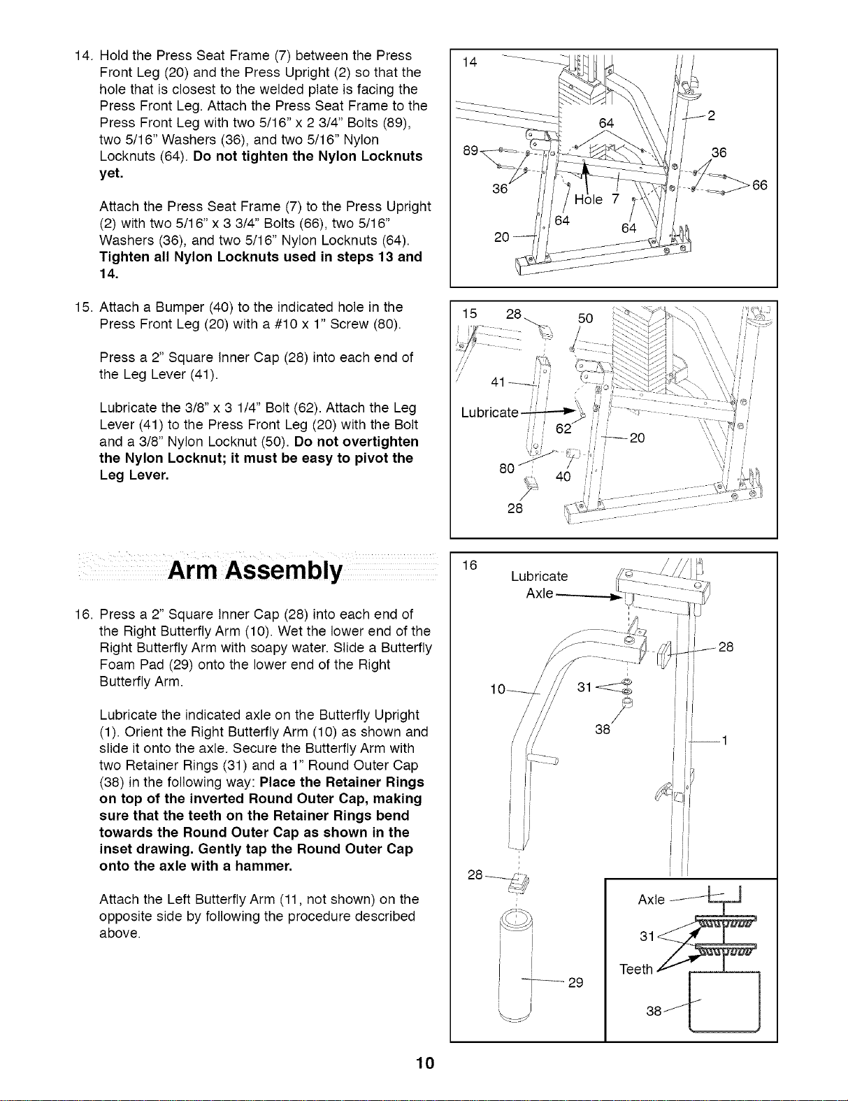
14. Hold the Press Seat Frame (7) between the Press
Front Leg (20) and the Press Upright (2) so that the
hole that is closest to the welded plate is facing the
Press Front Leg. Attach the Press Seat Frame to the
Press Front Leg with two 5/16" x 2 3/4" Bolts (89),
two 5/16" Washers (36), and two 5/16" Nylon
Locknuts (64). Do not tighten the Nylon Locknuts
yet.
Attach the Press Seat Frame (7) to the Press Upright
(2) with two 5/16" x 3 3/4" Bolts (66), two 5/16"
Washers (36), and two 5/16" Nylon Locknuts (64).
Tighten all Nylon Locknuts used in steps 13 and
14,
15. Attach a Bumper (40) to the indicated hole in the
Press Front Leg (20) with a #10 x 1" Screw (80).
Press a 2" Square Inner Cap (28) into each end of
the Leg Lever (41).
Lubricate the 3/8" x 3 1/4" Bolt (62). Attach the Leg
Lever (41) to the Press Front Leg (20) with the Bolt
and a 3/8" Nylon Locknut (50). Do not overtighten
the Nylon Locknut; it must be easy to pivot the
Leg Lever,
14
36
20
50
16. Press a 2" Square Inner Cap (28) into each end of
the Right Butterfly Arm (10). Wet the lower end of the
Right Butterfly Arm with soapy water• Slide a Butterfly
Foam Pad (29) onto the lower end of the Right
Butterfly Arm.
Lubricate the indicated axle on the Butterfly Upright
(1). Orient the Right Butterfly Arm (10) as shown and
slide it onto the axle. Secure the Butterfly Arm with
two Retainer Rings (31) and a 1" Round Outer Cap
(38) in the following way: Place the Retainer Rings
on top of the inverted Round Outer Cap, making
sure that the teeth on the Retainer Rings bend
towards the Round Outer Cap as shown in the
inset drawing. Gently tap the Round Outer Cap
onto the axle with a hammer,
Attach the Left Butterfly Arm (11, not shown) on the
opposite side by following the procedure described
above•
16
Lubricate
Axle
38
Axle
Teet3__
38J_ [_
10
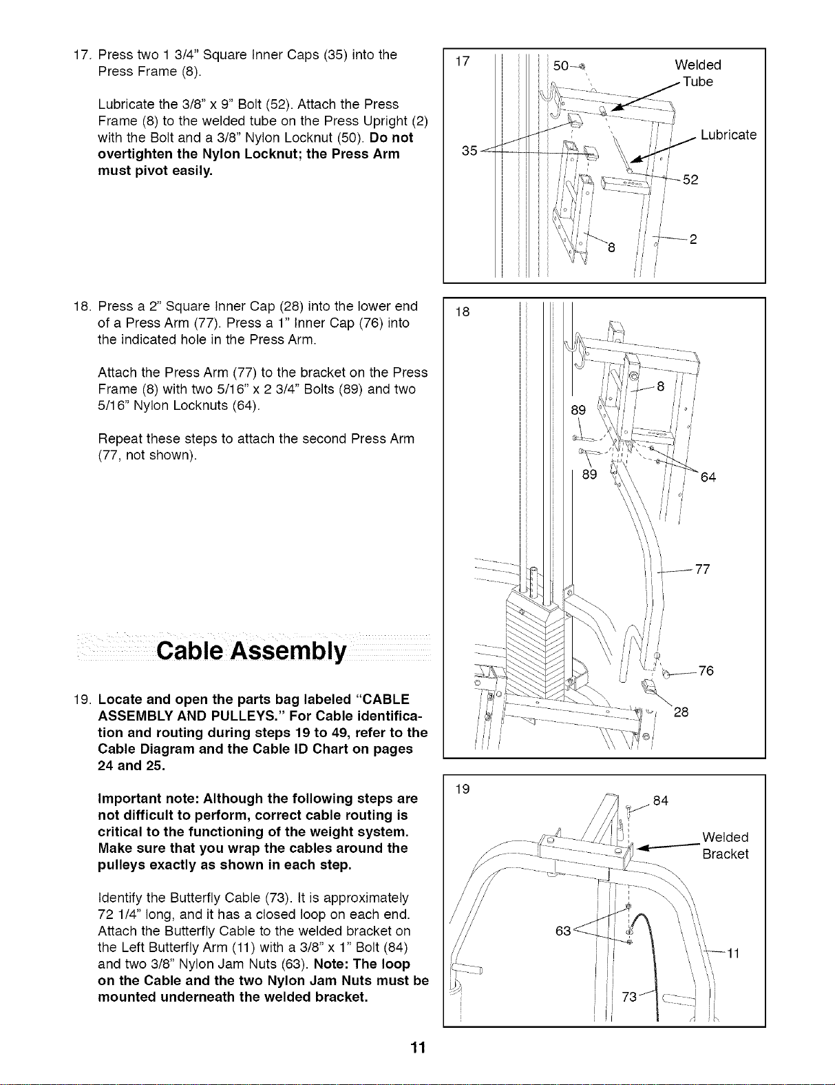
17. Press two 1 3/4" Square Inner Caps (35) into the
Press Frame (8).
Lubricate the 3/8" x 9" Bolt (52). Attach the Press
Frame (8) to the welded tube on the Press Upright (2)
with the Bolt and a 3/8" Nylon Locknut (50). Do not
overtighten the Nylon Locknut; the Press Arm
must pivot easily.
18. Press a 2" Square Inner Cap (28) into the lower end
of a Press Arm (77). Press a 1" Inner Cap (76) into
the indicated hole in the Press Arm.
Attach the Press Arm (77) to the bracket on the Press
Frame (8) with two 5/16" x 2 3/4" Bolts (89) and two
5/16" Nylon Locknuts (64).
Repeat these steps to attach the second Press Arm
(77, not shown).
19. Locate and open the parts bag labeled "CABLE
ASSEMBLY AND PULLEYS." For Cable identifica-
tion and routing during steps 19 to 49, refer to the
Cable Diagram and the Cable ID Chart on pages
24 and 25.
Important note: Although the following steps are
not difficult to perform, correct cable routing is
critical to the functioning of the weight system.
Make sure that you wrap the cables around the
pulleys exactly as shown in each step.
Identify the Butterfly Cable (73). It is approximately
72 1/4" long, and it has a closed loop on each end.
Attach the Butterfly Cable to the welded bracket on
the Left Butterfly Arm (11) with a 3/8" x 1" Bolt (84)
and two 3/8" Nylon Jam Nuts (63). Note: The loop
on the Cable and the two Nylon Jam Nuts must be
mounted underneath the welded bracket.
17
18
19
ii50
Welded
Lubricate
o/
_-_52
28
_ 84
Welded
Bracket
\ \,\
11
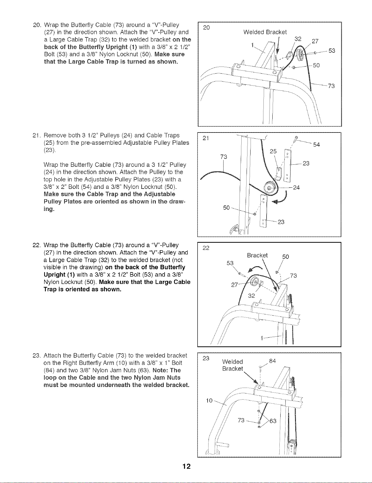
20, Wrap the Butterfly Cable (73) around a "V'-Pulley
(27) in the direction shown, Attach the "V'-Pulley and
a Large Cable Trap (32) to the welded bracket on the
beck of the Butterfly Upright (t) with a 3/8" x 2 1/2"
Bolt (53) and a 3/8" Nylon Locknut (50), Make sure
that the Large Cable Trap is turned as shown.
2O
Welded Bracket
32 27
21, Remove both 3 1/2" Pulleys (24) and Cable Traps
(25) from the pre-assembled Adjustable Pulley Plates
(23),
Wrap the Butterfly Cable (73) around a 3 1/2" Pulley
(24) in the direction shown, Attach the Pulley to the
top hole in the Adjustable Pulley Plates (23) with a
3/8" x 2" Bolt (54) and a 3/8" Nylon Locknut (50),
Make sure the Cable Trap end the Adjustable
Pulley Plates ere oriented as shown in the draw=
ing.
21
73
50
22. Wrap the Butterfly Cable (73) around a "V"-Pulley
(27) in the direction shown. Attach the "V"-Pulley and
a Large Cable Trap (32) to the welded bracket (not
visible in the drawing) on the back of the Butterfly
Upright (1) with a 3/8" x 2 1/2" Bolt (53) and a 3/8"
Nylon Locknut (50). Make sure that the Large Cable
Trap is oriented as shown,
22
53
\
Bracket
5O
j73
23, Attach the Butterfly Cable (73) to the welded bracket
on the Right Butterfly Arm (10) with a 3/8" x 1" Bolt
(84) and two 3/8" Nylon Jam Nuts (63), Note: The
loop on the Cable and the two Nylon Jam Nuts
must be mounted underneath the welded bracket.
23
Welded 84
Bracket _J
73
12
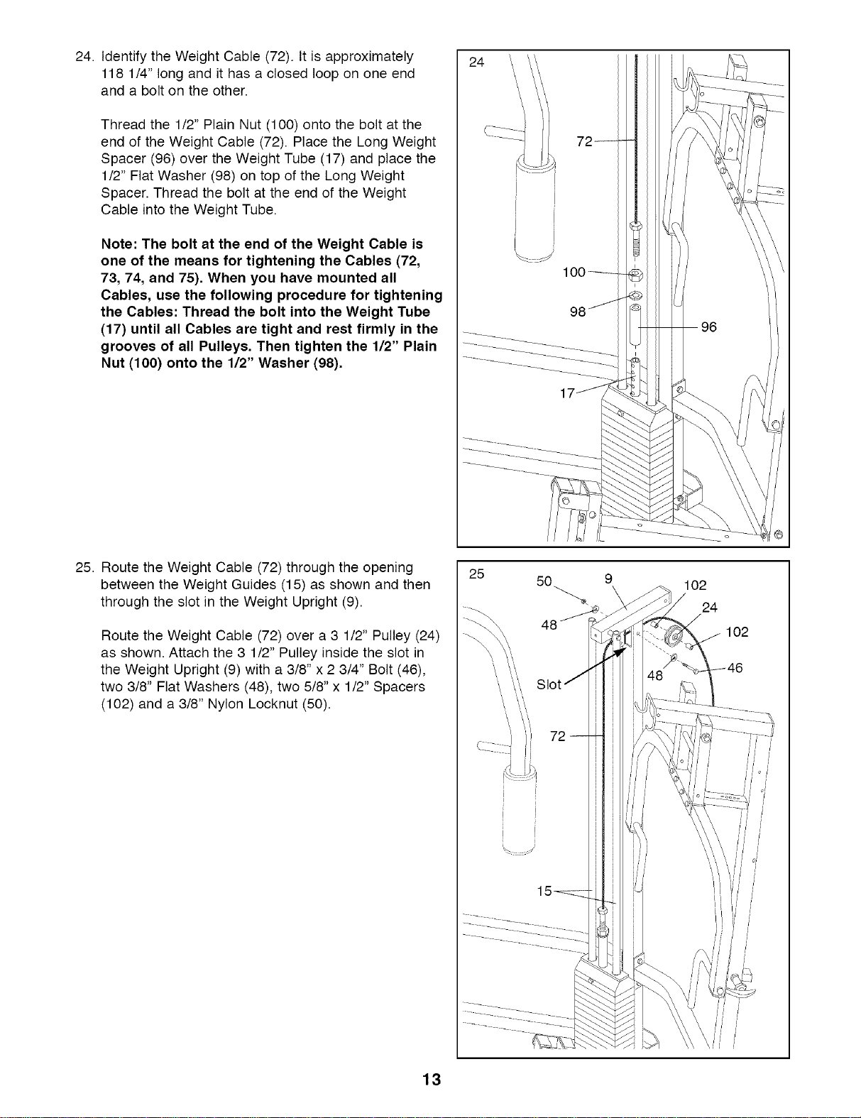
24. Identify the Weight Cable (72). It is approximately
118 1/4" long and it has a closed loop on one end
and a bolt on the other.
Thread the 1/2" Plain Nut (100) onto the bolt at the
end of the Weight Cable (72). Place the Long Weight
Spacer (96) over the Weight Tube (17) and place the
1/2" Flat Washer (98) on top of the Long Weight
Spacer. Thread the bolt at the end of the Weight
Cable into the Weight Tube.
Note: The bolt at the end of the Weight Cable is
one of the means for tightening the Cables (72,
73, 74, and 75). When you have mounted all
Cables, use the following procedure for tightening
the Cables: Thread the bolt into the Weight Tube
(17) until all Cables are tight and rest firmly in the
grooves of all Pulleys. Then tighten the 1/2" Plain
Nut (100) onto the 1/2" Washer (98).
25. Route the Weight Cable (72) through the opening
between the Weight Guides (15) as shown and then
through the slot in the Weight Upright (9).
Route the Weight Cable (72) over a 3 1/2" Pulley (24)
as shown. Attach the 3 1/2" Pulley inside the slot in
the Weight Upright (9) with a 3/8" x 2 3/4" Bolt (46),
two 3/8" Flat Washers (48), two 5/8" x 1/2" Spacers
(102) and a 3/8" Nylon Locknut (50).
24
25
50
102
24
102
72
13
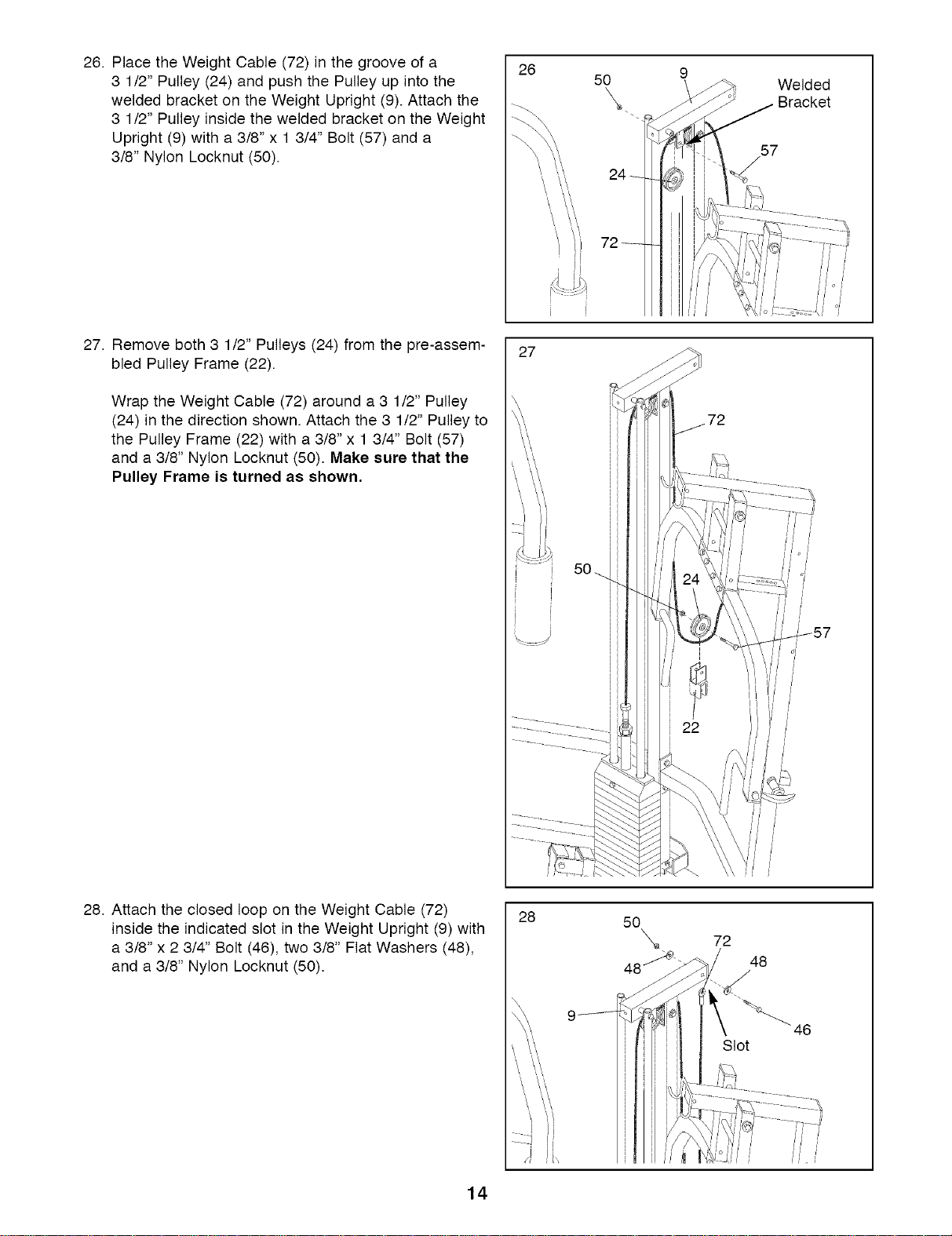
26. Place the Weight Cable (72) in the groove of a
3 1/2" Pulley (24) and push the Pulley up into the
welded bracket on the Weight Upright (9). Attach the
3 1/2" Pulley inside the welded bracket on the Weight
Upright (9) with a 3/8" x 1 3/4" Bolt (57) and a
3/8" Nylon Locknut (50).
27. Remove both 3 1/2" Pulleys (24) from the pre-assem-
bled Pulley Frame (22).
Wrap the Weight Cable (72) around a 3 1/2" Pulley
(24) in the direction shown. Attach the 3 1/2" Pulley to
the Pulley Frame (22) with a 3/8" x 1 3/4" Bolt (57)
and a 3/8" Nylon Locknut (50). Make sure that the
Pulley Frame is turned as shown,
26
'\ \\
I
27
50
Welded
Bracket
57
24
28. Attach the closed loop on the Weight Cable (72)
inside the indicated slot in the Weight Upright (9) with
a 3/8" x 2 3/4" Bolt (46), two 3/8" Flat Washers (48),
and a 3/8" Nylon Locknut (50).
28
50
\ 72
48
46
Slot
14
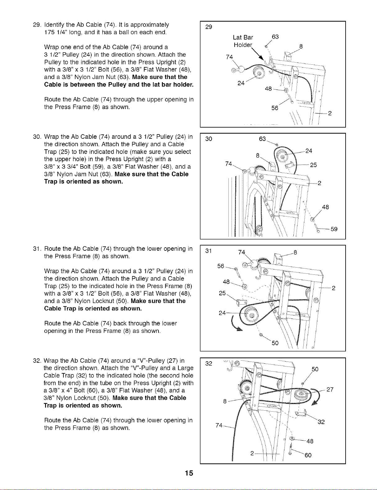
29. Identify the Ab Cable (74). It is approximately
175 1/4" long, and it has a ball on each end.
Wrap one end of the Ab Cable (74) around a
3 1/2" Pulley (24) in the direction shown. Attach the
Pulley to the indicated hole in the Press Upright (2)
with a 3/8" x 3 1/2" Bolt (56), a 3/8" Flat Washer (48),
and a 3/8" Nylon Jam Nut (63). Make sure that the
Cable is between the Pulley and the lat bar holder,
Route the Ab Cable (74) through the upper opening in
the Press Frame (8) as shown.
30. Wrap the Ab Cable (74) around a 3 1/2" Pulley (24) in
the direction shown. Attach the Pulley and a Cable
Trap (25) to the indicated hole (make sure you select
the upper hole) in the Press Upright (2) with a
3/8" x 3 3/4" Bolt (59), a 3/8" Flat Washer (48), and a
3/8" Nylon Jam Nut (63). Make sure that the Cable
Trap is oriented as shown,
29
30
Lat Bar 63
Holder d/
74
24
48
31. Route the Ab Cable (74) through the lower opening in
the Press Frame (8) as shown.
Wrap the Ab Cable (74) around a 3 1/2" Pulley (24) in
the direction shown. Attach the Pulley and a Cable
Trap (25) to the indicated hole in the Press Frame (8)
with a 3/8" x 3 1/2" Bolt (56), a 3/8" Flat Washer (48),
and a 3/8" Nylon Locknut (50). Make sure that the
Cable Trap is oriented as shown,
Route the Ab Cable (74) back through the lower
opening in the Press Frame (8) as shown.
31
32. Wrap the Ab Cable (74) around a "V"-Pulley (27) in
the direction shown. Attach the "V"-Pulley and a Large
Cable Trap (32) to the indicated hole (the second hole
from the end) in the tube on the Press Upright (2) with
a 3/8" x 4" Bolt (60), a 3/8" Flat Washer (48), and a
3/8" Nylon Locknut (50). Make sure that the Cable
Trap is oriented as shown,
Route the Ab Cable (74) through the lower opening in
the Press Frame (8) as shown.
32
60
27
15
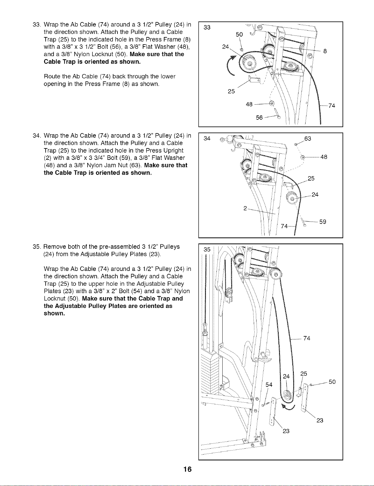
33. Wrap the Ab Cable (74) around a 3 1/2" Pulley (24) in
the direction shown. Attach the Pulley and a Cable
Trap (25) to the indicated hole in the Press Frame (8)
with a 3/8" x 3 1/2" Bolt (56), a 3/8" Flat Washer (48),
and a 3/8" Nylon Locknut (50). Make sure that the
Cable Trap is oriented as shown,
Route the Ab Cable (74) back through the lower
opening in the Press Frame (8) as shown.
33
50
25
z
/
48
56
34. Wrap the Ab Cable (74) around a 3 1/2" Pulley (24) in
the direction shown. Attach the Pulley and a Cable
Trap (25) to the indicated hole in the Press Upright
(2) with a 3/8" x 3 3/4" Bolt (59), a 3/8" Flat Washer
(48) and a 3/8" Nylon Jam Nut (63). Make sure that
the Cable Trap is oriented as shown,
35. Remove both of the pre-assembled 3 1/2" Pulleys
(24) from the Adjustable Pulley Plates (23).
Wrap the Ab Cable (74) around a 3 1/2" Pulley (24) in
the direction shown. Attach the Pulley and a Cable
Trap (25) to the upper hole in the Adjustable Pulley
Plates (23) with a 3/8" x 2" Bolt (54) and a 3/8" Nylon
Locknut (50). Make sure that the Cable Trap and
the Adjustable Pulley Plates are oriented as
shown,
34
25
74
25
23
23
16
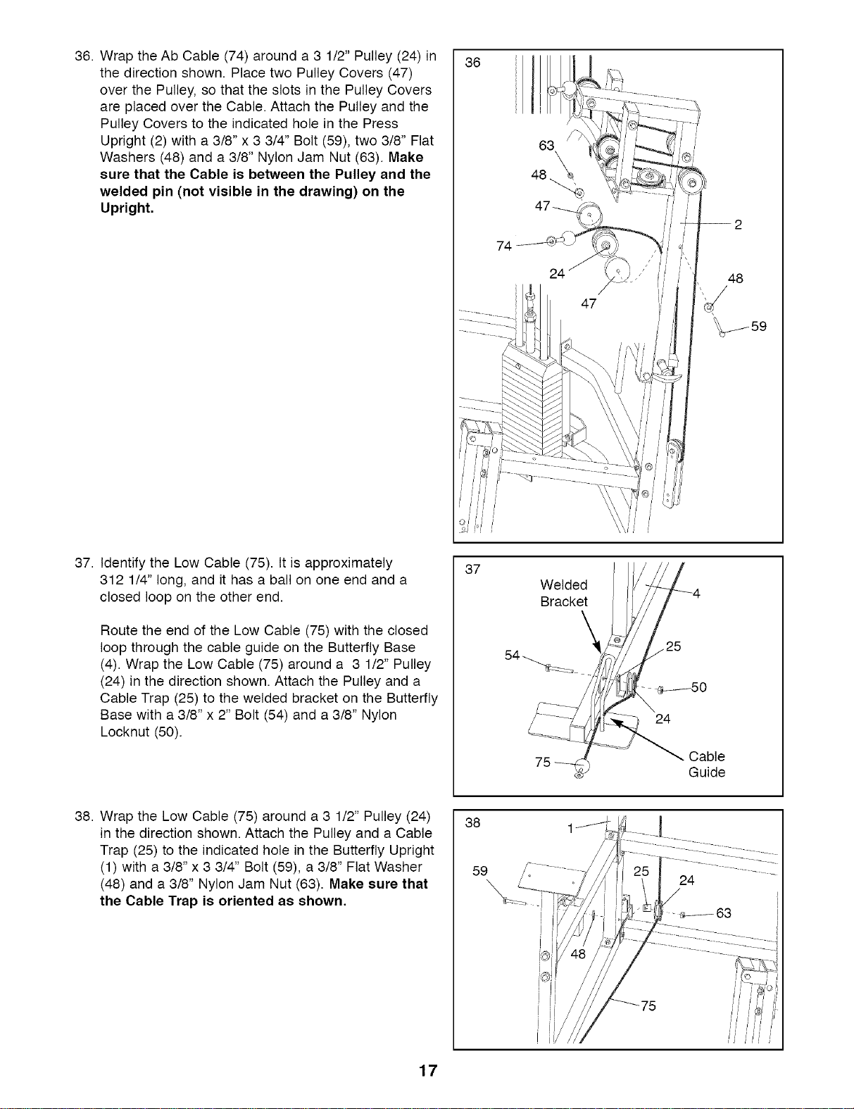
36. Wrap the Ab Cable (74) around a 3 1/2" Pulley (24) in
the direction shown. Place two Pulley Covers (47)
over the Pulley, so that the slots in the Pulley Covers
are placed over the Cable. Attach the Pulley and the
Pulley Covers to the indicated hole in the Press
Upright (2) with a 3/8" x 3 3/4" Bolt (59), two 3/8" Flat
Washers (48) and a 3/8" Nylon Jam Nut (63). Make
sure that the Cable is between the Pulley and the
welded pin (not visible in the drawing) on the
Upright.
36
74
24
48
37. Identify the Low Cable (75). It is approximately
312 1/4" long, and it has a ball on one end and a
closed loop on the other end.
Route the end of the Low Cable (75) with the closed
loop through the cable guide on the Butterfly Base
(4). Wrap the Low Cable (75) around a 3 1/2" Pulley
(24) in the direction shown. Attach the Pulley and a
Cable Trap (25) to the welded bracket on the Butterfly
Base with a 3/8" x 2" Bolt (54) and a 3/8" Nylon
Locknut (50).
37
24
Cable
Guide
38. Wrap the Low Cable (75) around a 3 1/2" Pulley (24)
in the direction shown. Attach the Pulley and a Cable
Trap (25) to the indicated hole in the Butterfly Upright
(1) with a 3/8" x 3 3/4" Bolt (59), a 3/8" Flat Washer
(48) and a 3/8" Nylon Jam Nut (63). Make sure that
the Cable Trap is oriented as shown,
38
59
17
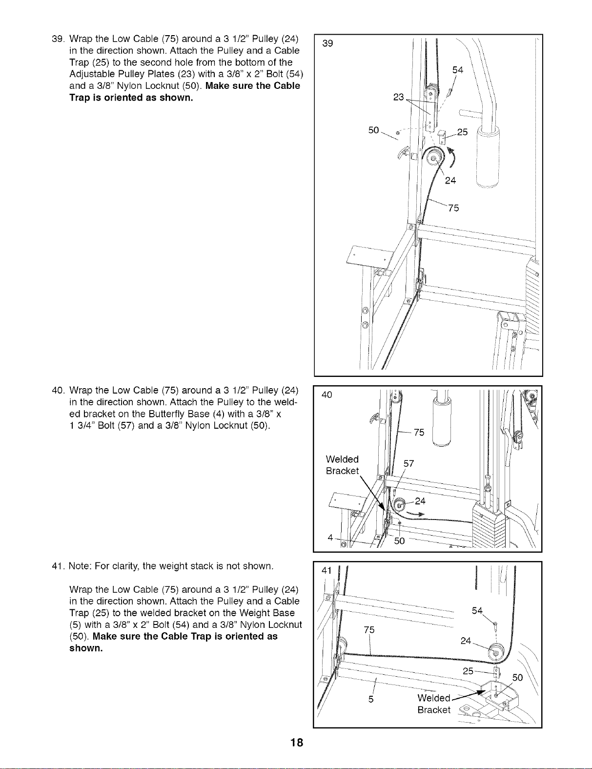
39. Wrap the Low Cable (75) around a 3 1/2" Pulley (24)
in the direction shown. Attach the Pulley and a Cable
Trap (25) to the second hole from the bottom of the
Adjustable Pulley Plates (23) with a 3/8" x 2" Bolt (54)
and a 3/8" Nylon Locknut (50). Make sure the Cable
Trap is oriented as shown,
39
23
40. Wrap the Low Cable (75) around a 3 1/2" Pulley (24)
in the direction shown. Attach the Pulley to the weld-
ed bracket on the Butterfly Base (4) with a 3/8" x
1 3/4" Bolt (57) and a 3/8" Nylon Locknut (50).
41. Note: For clarity, the weight stack is not shown.
Wrap the Low Cable (75) around a 3 1/2" Pulley (24)
in the direction shown. Attach the Pulley and a Cable
Trap (25) to the welded bracket on the Weight Base
(5) with a 3/8" x 2" Bolt (54) and a 3/8" Nylon Locknut
(50). Make sure the Cable Trap is oriented as
shown,
40
75
Welded
Bracket
50
75
54
Bracket
o
18
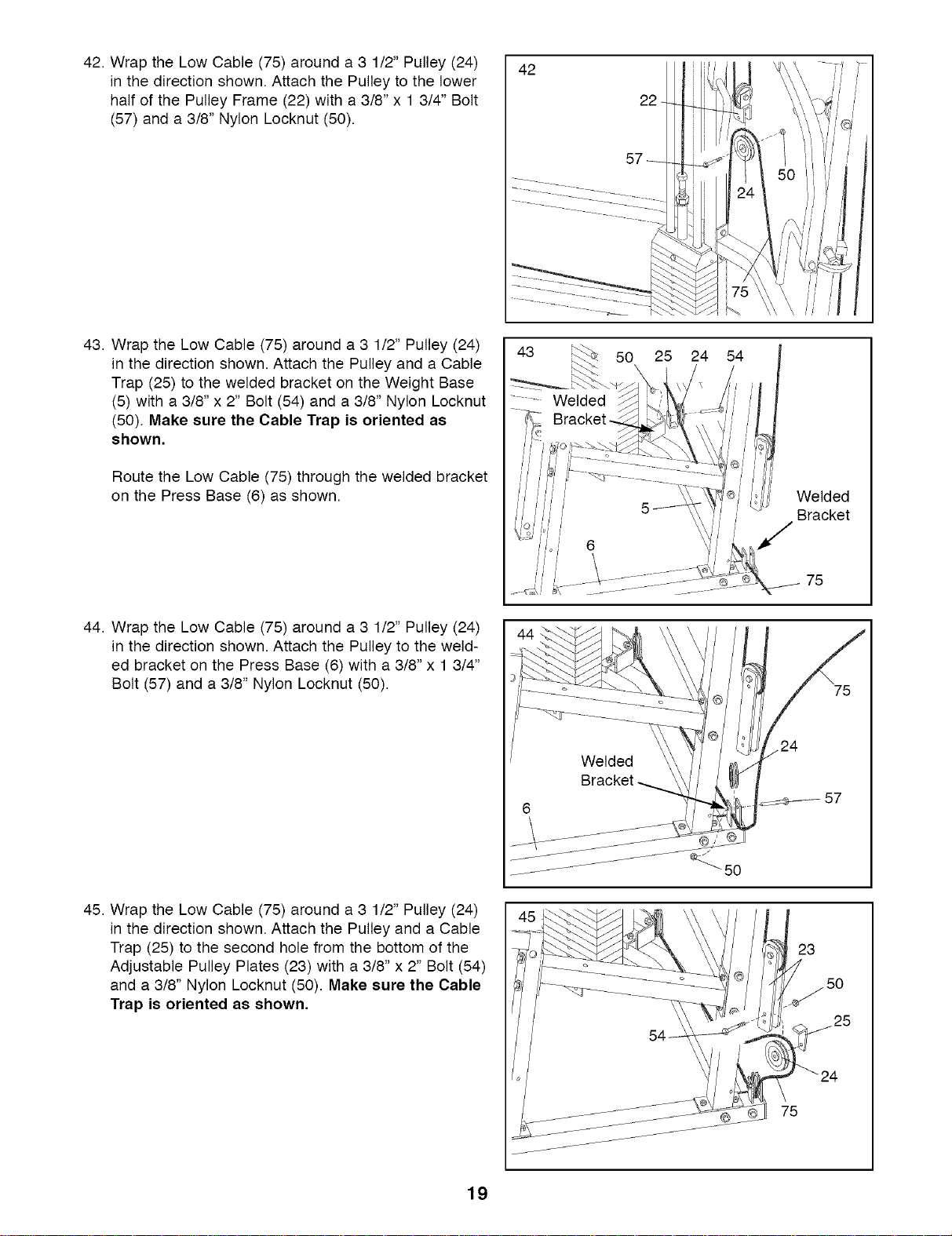
42. Wrap the Low Cable (75) around a 3 1/2" Pulley (24)
in the direction shown. Attach the Pulley to the lower
half of the Pulley Frame (22) with a 3/8" x 1 3/4" Bolt
(57) and a 3/8" Nylon Locknut (50).
43. Wrap the Low Cable (75) around a 3 1/2" Pulley (24)
in the direction shown. Attach the Pulley and a Cable
Trap (25) to the welded bracket on the Weight Base
(5) with a 3/8" x 2" Bolt (54) and a 3/8" Nylon Locknut
(50). Make sure the Cable Trap is oriented as
shown,
Route the Low Cable (75) through the welded bracket
on the Press Base (6) as shown.
42
43 50 25 24 54
Bracket
........ Welded
Welded
Bracket
75
44. Wrap the Low Cable (75) around a 3 1/2" Pulley (24)
in the direction shown. Attach the Pulley to the weld-
ed bracket on the Press Base (6) with a 3/8" x 1 3/4"
Bolt (57) and a 3/8" Nylon Locknut (50).
45. Wrap the Low Cable (75) around a 3 1/2" Pulley (24)
in the direction shown. Attach the Pulley and a Cable
Trap (25) to the second hole from the bottom of the
Adjustable Pulley Plates (23) with a 3/8" x 2" Bolt (54)
and a 3/8" Nylon Locknut (50). Make sure the Cable
Trap is oriented as shown,
75
57
23
75
19
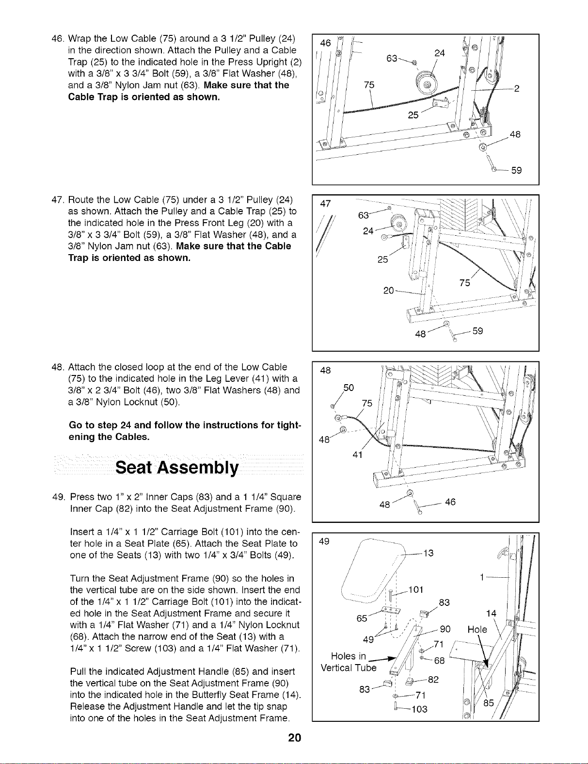
46. Wrap the Low Cable (75) around a 3 1/2" Pulley (24)
in the direction shown. Attach the Pulley and a Cable
Trap (25) to the indicated hole in the Press Upright (2)
with a 3/8" x 3 3/4" Bolt (59), a 3/8" Flat Washer (48),
and a 3/8" Nylon Jam nut (63). Make sure that the
Cable Trap is oriented as shown,
47. Route the Low Cable (75) under a 3 1/2" Pulley (24)
as shown. Attach the Pulley and a Cable Trap (25) to
the indicated hole in the Press Front Leg (20) with a
3/8" x 3 3/4" Bolt (59), a 3/8" Flat Washer (48), and a
3/8" Nylon Jam nut (63). Make sure that the Cable
Trap is oriented as shown.
47
25
48. Attach the closed loop at the end of the Low Cable
(75) to the indicated hole in the Leg Lever (41) with a
3/8" x 2 3/4" Bolt (46), two 3/8" Flat Washers (48) and
a 3/8" Nylon Locknut (50).
Go to step 24 and follow the instructions for tight-
ening the Cables.
49. Press two 1" x 2" Inner Caps (83) and a 1 1/4" Square
Inner Cap (82) into the Seat Adjustment Frame (90).
Insert a 1/4" x 1 1/2" Carriage Bolt (101) into the cen-
ter hole in a Seat Plate (65). Attach the Seat Plate to
one of the Seats (13) with two 1/4" x 3/4" Bolts (49).
Turn the Seat Adjustment Frame (90) so the holes in
the vertical tube are on the side shown. Insert the end
of the 1/4" x 1 1/2" Carriage Bolt (101) into the indicat-
ed hole in the Seat Adjustment Frame and secure it
with a 1/4" Flat Washer (71) and a 1/4" Nylon Locknut
(68). Attach the narrow end of the Seat (13) with a
1/4" x 1 1/2" Screw (103) and a 1/4" Flat Washer (71).
Pull the indicated Adjustment Handle (85) and insert
the vertical tube on the Seat Adjustment Frame (90)
into the indicated hole in the Butterfly Seat Frame (14).
Release the Adjustment Handle and let the tip snap
into one of the holes in the Seat Adjustment Frame.
2O
48
50
_/ 75
48 _
41
49
i/i
90
'_71
Holes in _---68
Vertical Tube L_y
_-_71
--lO3
j
1_:
14 i_
Hole \ .....
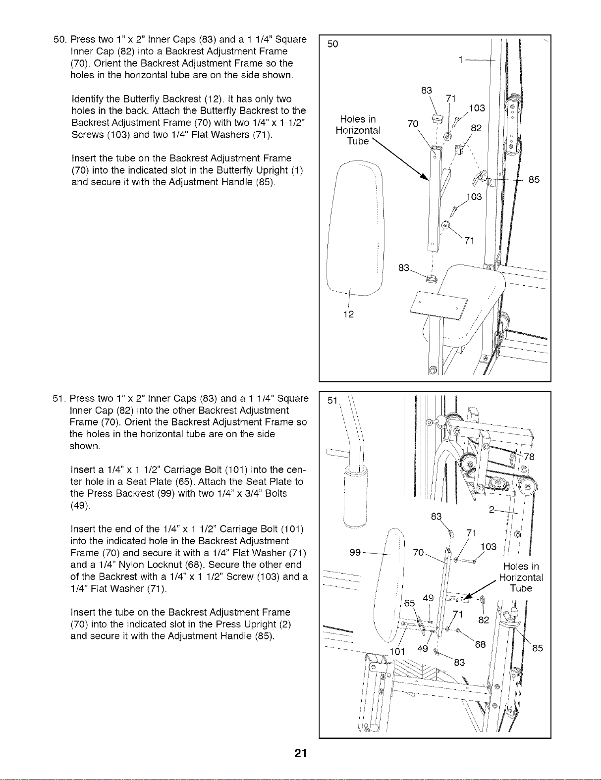
50.Presstwo1"x2"InnerCaps(83)anda11/4"Square
InnerCap(82)intoaBackrestAdjustmentFrame
(70).OrienttheBackrestAdjustmentFramesothe
holesinthehorizontaltubeareonthesideshown.
IdentifytheButterflyBackrest(12).Ithasonlytwo
holesintheback.AttachtheButterflyBackresttothe
BackrestAdjustmentFrame(70)withtwo1/4"x11/2"
Screws(103)andtwo1/4"FlatWashers(71).
InsertthetubeontheBackrestAdjustmentFrame
(70)intotheindicatedslotintheButterflyUpright(1)
andsecureitwiththeAdjustmentHandle(85).
50
Holesin
Horizontal
/
12
83
70
71
103
/
85
51. Press two 1" x 2" Inner Caps (83) and a 1 1/4" Square
Inner Cap (82) into the other Backrest Adjustment
Frame (70). Orient the Backrest Adjustment Frame so
the holes in the horizontal tube are on the side
shown.
Insert a 1/4" x 1 1/2" Carriage Bolt (101) into the cen-
ter hole in a Seat Plate (65). Attach the Seat Plate to
the Press Backrest (99) with two 1/4" x 3/4" Bolts
(49).
Insert the end of the 1/4" x 1 1/2" Carriage Bolt (101)
into the indicated hole in the Backrest Adjustment
Frame (70) and secure it with a 1/4" Flat Washer (71)
and a 1/4" Nylon Locknut (68). Secure the other end
of the Backrest with a 1/4" x 1 1/2" Screw (103) and a
1/4" Flat Washer (71).
Insert the tube on the Backrest Adjustment Frame
(70) into the indicated slot in the Press Upright (2)
and secure it with the Adjustment Handle (85).
......
I
99_
/
101
83
71
'i 103 _
iL-J
Holes in
Horizontal
Tube
49 _83
21
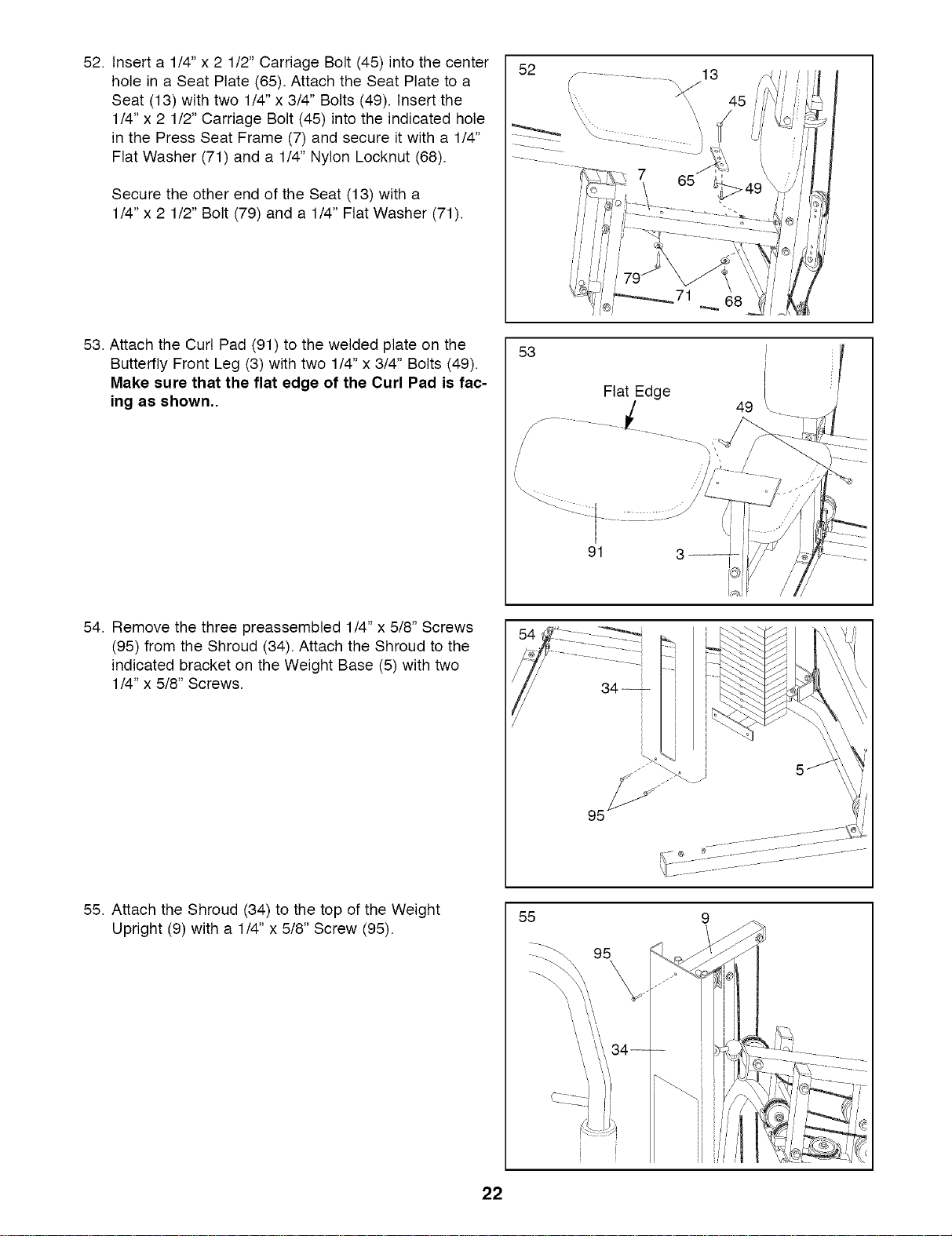
52. Insert a 1/4" x 2 1/2" Carriage Bolt (45) into the center
hole in a Seat Plate (65). Attach the Seat Plate to a
Seat (13) with two 1/4" x 3/4" Bolts (49). Insert the
1/4" x 2 1/2" Carriage Bolt (45) into the indicated hole
in the Press Seat Frame (7) and secure it with a 1/4"
Flat Washer (71) and a 1/4" Nylon Locknut (68).
Secure the other end of the Seat (13) with a
1/4" x 2 1/2" Bolt (79) and a 1/4" Flat Washer (71).
52
53. Attach the Curl Pad (91) to the welded plate on the
Butterfly Front Leg (3) with two 1/4" x 3/4" Bolts (49).
Make sure that the flat edge of the Curl Pad is fac-
ing as shown,.
53
Flat Edge
91 3--
49
54. Remove the three preassembled 1/4" x 5/8" Screws
(95) from the Shroud (34). Attach the Shroud to the
indicated bracket on the Weight Base (5) with two
1/4" x 5/8" Screws.
55. Attach the Shroud (34) to the top of the Weight
Upright (9) with a 1/4" x 5/8" Screw (95).
55
95
22
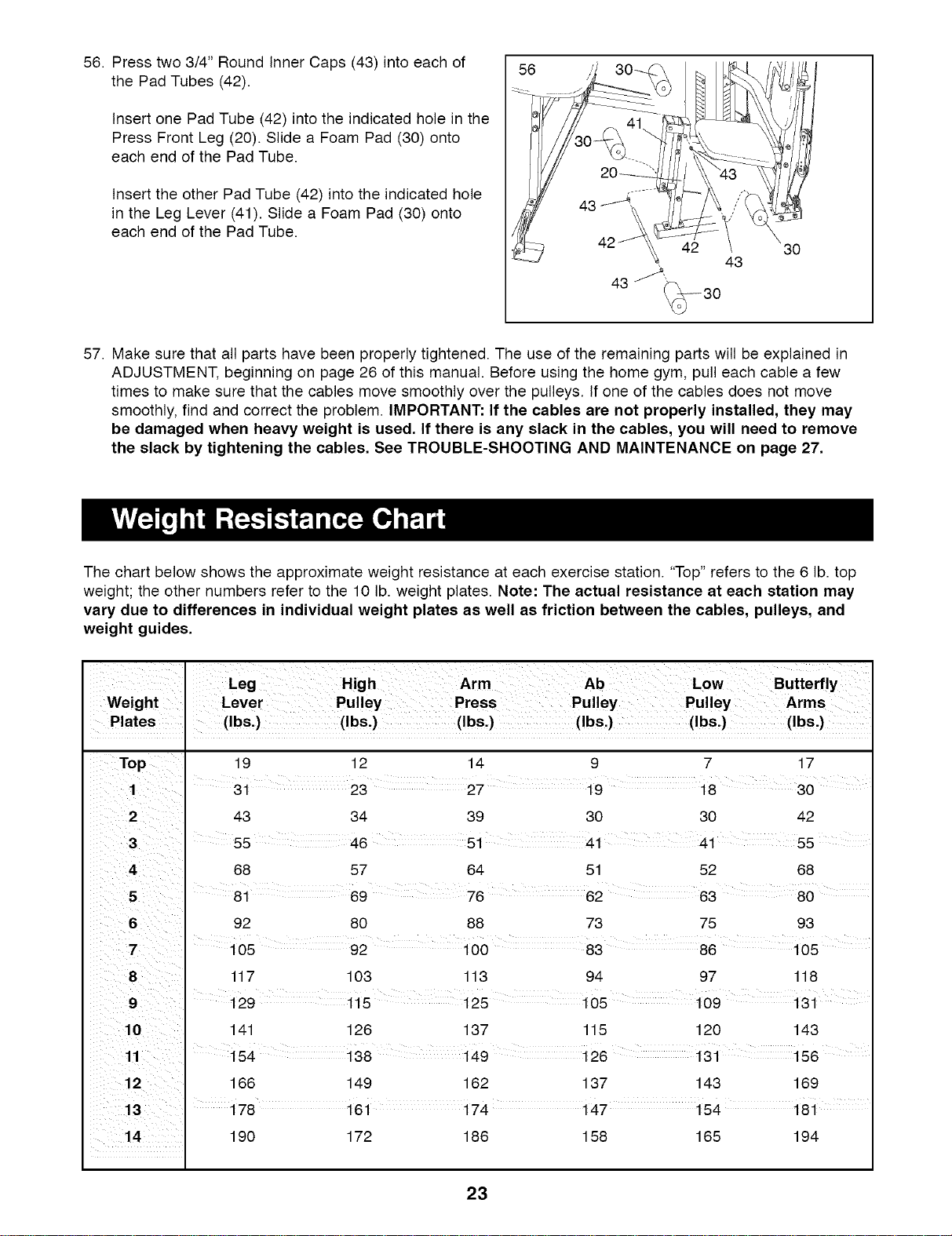
56. Press two 3/4" Round Inner Caps (43) into each of
the Pad Tubes (42).
Insert one Pad Tube (42) into the indicated hole in the
Press Front Leg (20). Slide a Foam Pad (30) onto
each end of the Pad Tube.
Insert the other Pad Tube (42) into the indicated hole
in the Leg Lever (41). Slide a Foam Pad (30) onto
each end of the Pad Tube.
56
30
57. Make sure that all parts have been properly tightened. The use of the remaining parts will be explained in
ADJUSTMENT, beginning on page 26 of this manual. Before using the home gym, pull each cable a few
times to make sure that the cables move smoothly over the pulleys. If one of the cables does not move
smoothly, find and correct the problem. IMPORTANT: If the cables are not properly installed, they may
be damaged when heavy weight is used, If there is any slack in the cables, you will need to remove
the slack by tightening the cables, See TROUBLE-SHOOTING AND MAINTENANCE on page 27,
The chart below shows the approximate weight resistance at each exercise station. "Top" refers to the 6 lb. top
weight; the other numbers refer to the 10 lb. weight plates. Note: The actual resistance at each station may
vary due to differences in individual weight plates as well as friction between the cables, pulleys, and
weight guides.
Weight
Plates . (Ibs.) (Ibs.) (Ibs.) (Ibs.) (Ibs.) (Ibs.)
2 43 34 39 30 30 42
51 41 41 55
4 68 57 64 51 52 68
5 81 69 76 62 63 80
92 80 88 73 75 93
105 92 100 83 86 105
8 117 103 113 94 97 118
141 126 137 115 120 143
166 149 162 137 143 169
I
13 ' 178 161 174 147 154 181
190 172 186 158 165 194
23
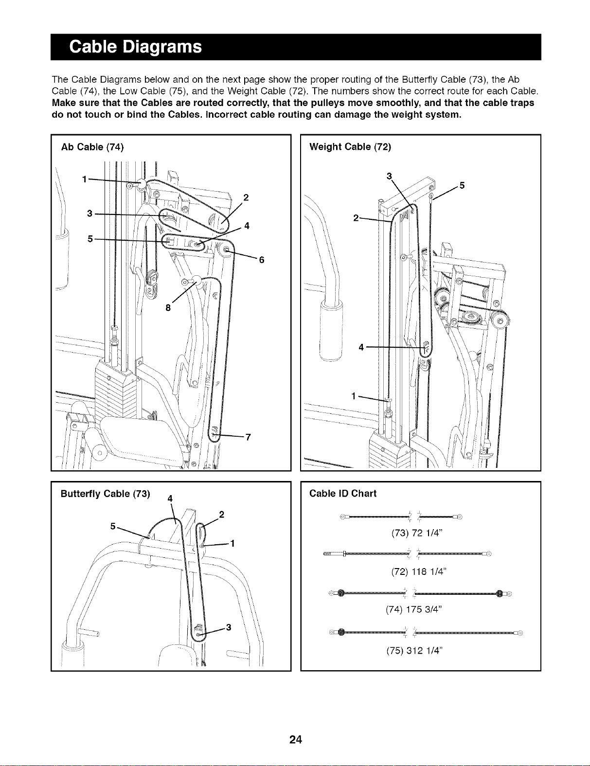
The Cable Diagrams below and on the next page show the proper routing of the Butterfly Cable (73), the Ab
Cable (74), the Low Cable (75), and the Weight Cable (72). The numbers show the correct route for each Cable.
Make sure that the Cables are routed correctly, that the pulleys move smoothly, and that the cable traps
do not touch or bind the Cables. Incorrect cable routing can damage the weight system.
Ab Cable (74)
2
4
Weight Cable (72)
3
\
Butterfly Cable (73)
Cable ID Chart
(,,F_
(73) 72 1/4"
(72) 118 1/4"
J,.
(74) 175 3/4"
FjI
(75) 312 1/4"
24
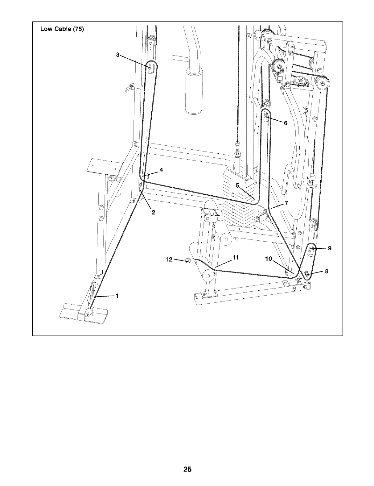
Low Cable (75)
12
11
10
25
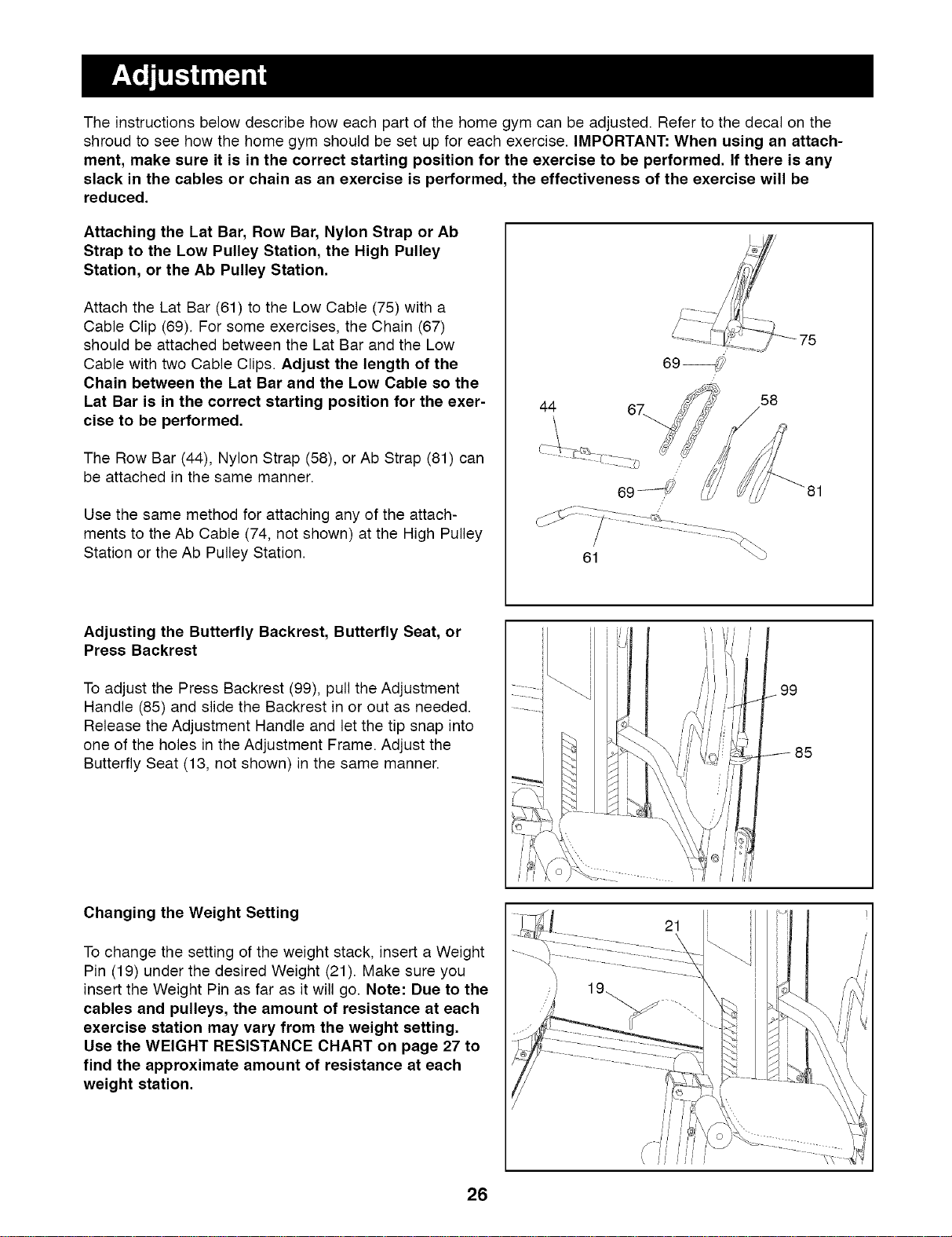
The instructions below describe how each part of the home gym can be adjusted. Refer to the decal on the
shroud to see how the home gym should be set up for each exercise. IMPORTANT: When using an attach-
ment, make sure it is in the correct starting position for the exercise to be performed. If there is any
slack in the cables or chain as an exercise is performed, the effectiveness of the exercise will be
reduced.
Attaching the Lat Bar, Row Bar, Nylon Strap or Ab
Strap to the Low Pulley Station, the High Pulley
Station, or the Ab Pulley Station.
Attach the Lat Bar (61) to the Low Cable (75) with a
Cable Clip (69). For some exercises, the Chain (67)
should be attached between the Lat Bar and the Low
Cable with two Cable Clips. Adjust the length of the
Chain between the Lat Bar and the Low Cable so the
Lat Bar is in the correct starting position for the exer-
cise to be performed,
The Row Bar (44), Nylon Strap (58), or Ab Strap (81) can
be attached in the same manner.
Use the same method for attaching any of the attach-
ments to the Ab Cable (74, not shown) at the High Pulley
Station or the Ab Pulley Station.
44
61
58
Adjusting the Butterfly Backrest, Butterfly Seat, or
Press Backrest
To adjust the Press Backrest (99), pull the Adjustment
Handle (85) and slide the Backrest in or out as needed.
Release the Adjustment Handle and let the tip snap into
one of the holes in the Adjustment Frame. Adjust the
Butterfly Seat (13, not shown) in the same manner.
........ i
99
J 85
Changing the Weight Setting
To change the setting of the weight stack, insert a Weight
Pin (19) under the desired Weight (21). Make sure you
insert the Weight Pin as far as it will go. Note: Due to the
cables and pulleys, the amount of resistance at each
exercise station may vary from the weight setting.
Use the WEIGHT RESISTANCE CHART on page 27 to
find the approximate amount of resistance at each
weight station,
26
21
Inspectandtightenallpartseachtimeyouusethehomegym.Replaceanywornpartsimmediately.Thehome
gymcanbecleanedusingadampclothandmildnon-abrasivedetergent.Donotusesolvents.
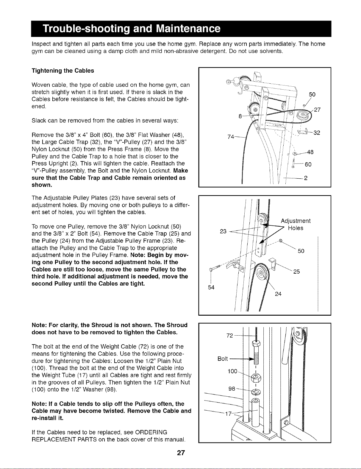
Tightening the Cables
Woven cable, the type of cable used on the home gym, can
stretch slightly when it is first used. If there is slack in the
Cables before resistance is felt, the Cables should be tight-
ened.
Slack can be removed from the cables in several ways:
Remove the 3/8" x 4" Bolt (60), the 3/8" Flat Washer (48),
the Large Cable Trap (32), the "V"-Pulley (27) and the 3/8"
Nylon Locknut (50) from the Press Frame (8). Move the
Pulley and the Cable Trap to a hole that is closer to the
Press Upright (2). This will tighten the cable. Reattach the
"V"-Pulley assembly, the Bolt and the Nylon Locknut. Make
sure that the Cable Trap and Cable remain oriented as
shown.
The Adjustable Pulley Plates (23) have several sets of
adjustment holes. By moving one or both pulleys to a differ-
ent set of holes, you will tighten the cables.
To move one Pulley, remove the 3/8" Nylon Locknut (50)
and the 3/8" x 2" Bolt (54). Remove the Cable Trap (25) and
the Pulley (24) from the Adjustable Pulley Frame (23). Re-
attach the Pulley and the Cable Trap to the appropriate
adjustment hole in the Pulley Frame. Note: Begin by mov-
ing one Pulley to the second adjustment hole. If the
Cables are still too loose, move the same Pulley to the
third hole. If additional adjustment is needed, move the
second Pulley until the Cables are tight.
23
Adjustment
THoles
5O
25
54
24
Note: For clarity, the Shroud is not shown. The Shroud
does not have to be removed to tighten the Cables.
The bolt at the end of the Weight Cable (72) is one of the
means for tightening the Cables. Use the following proce-
dure for tightening the Cables: Loosen the 1/2" Plain Nut
(100). Thread the bolt at the end of the Weight Cable into
the Weight Tube (17) until all Cables are tight and rest firmly
in the grooves of all Pulleys. Then tighten the 1/2" Plain Nut
(100) onto the 1/2" Washer (98).
Note: If a Cable tends to slip off the Pulleys often, the
Cable may have become twisted. Remove the Cable and
re-install it.
If the Cables need to be replaced, see ORDERING
REPLACEMENT PARTS on the back cover of this manual.
Bolt
2)
27
5/16" Washer (36)
1/4" Flat Washer (71)
©?
1/4" Nylon Locknut (68)
\
3/8" Flat Washer (48)
3/8" Nylon Jamnut (63)
3/8" Nylon Locknut (50)
1" Tap Screw (80)
1/4" x 3/4" Bolt (49)
i
5/8 x 1/2 Spacer (102)
1/4" x 5/8" Screw (95)
5/16" Nylon Locknut (64)
1/4" x 2 1/2" Carriage Bolt (45)
1/4" x 2 1/2" Bolt (79)
1/4" x 1 1/2" Carriage Bolt (101)
5/16" x 3 3/4" Bolt (66)
5/18" x 2 3/4" Bolt (89) 5/18" x 2 1/2" Carriage Bolt (92)
U9
d')
o
QO
x
CO
3/8" x 1" Bolt (84)
3/8" x 1 3/4" Bolt (57)
3/8" x 2" Bolt (54)
3/8" x 2 1/2" Bolt (53)
3/8" x 2 3/4" Bolt (46)
3/8" x 3 1/4" Bolt (62)
3/8" x 3 1/2" Bo_t (56)
3/8" x 3 3/4" Bolt (59)
3/8" x 4" Bolt (60)
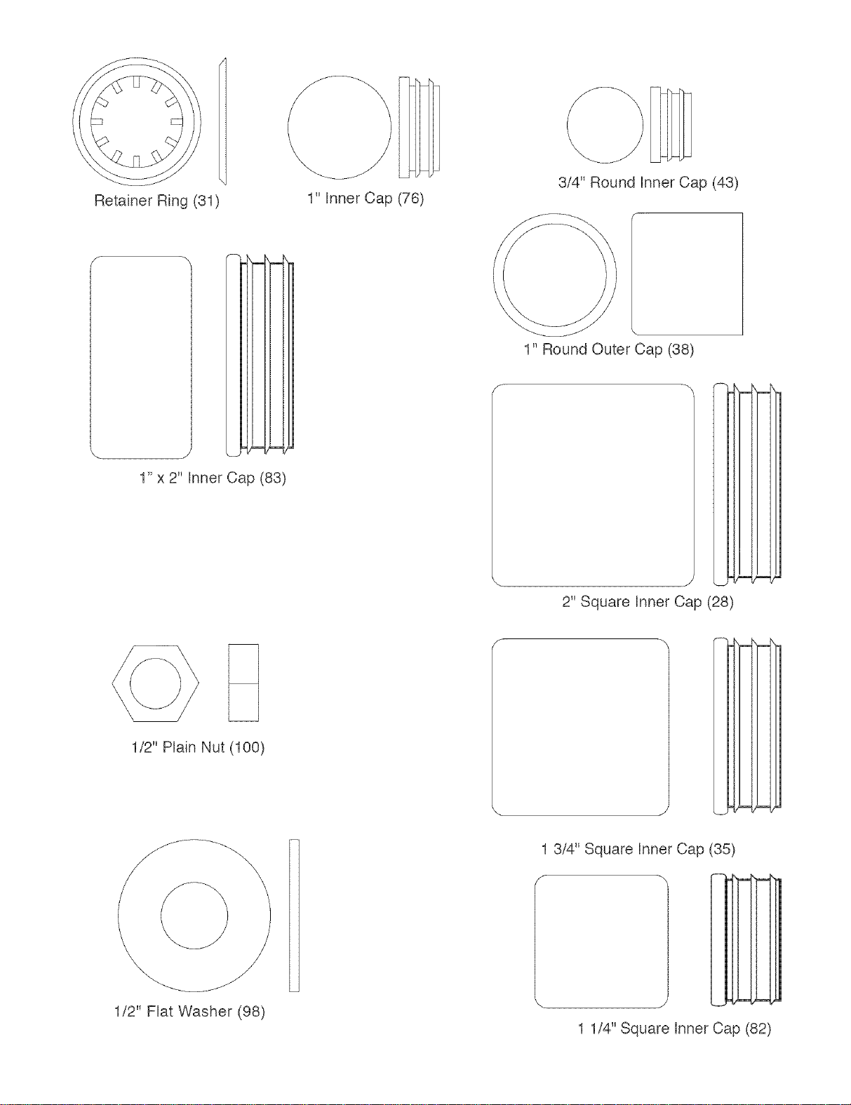
RetainerRing(31)
1"InnerCap(76)
3/4"RoundInnerCap(43)
E
j
1" x 2" Inner Cap (83)
1" Round Outer Cap (38)
2" Square Inner Oap (28)
I
1/2" Plain Nut (100)
\
1/2" Flat Washer (98)
E
m
1 3/4" Square Inner Cap (35)
1 1/4" Square Inner Cap (82)
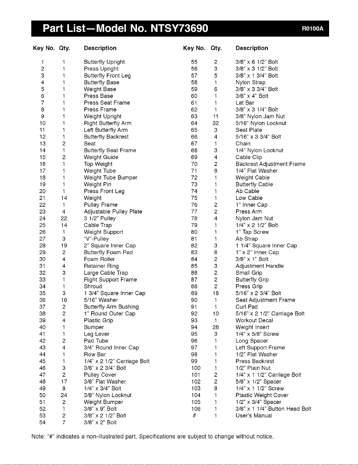
Key No. Qty. Description Key No, Qty, Description
1 1 Butterfly Upright 55 2 3/8" x 6 1/2" Bolt
2 1 Press Upright 56 3 3/8" x 3 1/2" Bolt
3 1 Butterfly Front Leg 57 5 3/8" x 1 3/4" Bolt
4 1 Butterfly Base 58 1 Nylon Strap
5 1 Weight Base 59 6 3/8" x 3 3/4" Bolt
6 1 Press Base 60 1 3/8" x 4" Bolt
7 1 Press Seat Frame 61 1 Lat Bar
8 1 Press Frame 62 1 3/8" x 3 1/4" Bolt
9 1 Weight Upright 63 11 3/8" Nylon Jam Nut
10 1 Right Butterfly Arm 64 32 5/16" Nylon Locknut
11 1 Left Butterfly Arm 65 3 Seat Plate
12 1 Butterfly Backrest 66 4 5/16" x 3 3/4" Bolt
13 2 Seat 67 1 Chain
14 1 Butterfly Seat Frame 68 3 1/4" Nylon Locknut
15 2 Weight Guide 69 4 Cable Clip
16 1 Top Weight 70 2 Backrest Adjustment Frame
17 1 Weight Tube 71 8 1/4" Flat Washer
18 1 Weight Tube Bumper 72 1 Weight Cable
19 1 Weight Pin 73 1 Butterfly Cable
20 1 Press Front Leg 74 1 Ab Cable
21 14 Weight 75 1 Low Cable
22 1 Pulley Frame 76 2 1" Inner Cap
23 4 Adjustable Pulley Plate 77 2 Press Arm
24 22 3 1/2" Pulley 78 4 Nylon Jam Nut
25 14 Cable Trap 79 1 1/4" x 2 1/2" Bolt
26 1 Weight Support 80 1 1" Tap Screw
27 3 "V"- Pulley 81 1 Ab Strap
28 19 2" Square Inner Cap 82 3 1 1/4" Square Inner Cap
29 2 Butterfly Foam Pad 83 6 1" x 2" Inner Cap
30 4 Foam Roller 84 2 3/8" x 1" Bolt
31 4 Retainer Ring 85 3 Adjustment Handle
32 3 Large Cable Trap 86 2 Small Grip
33 1 Right Support Frame 87 2 Butterfly Grip
34 1 Shroud 88 2 Press Grip
35 3 1 3/4" Square Inner Cap 89 18 5/16" x 2 3/4" Bolt
36 16 5/16" Washer 90 1 Seat Adjustment Frame
37 2 Butterfly Arm Bushing 91 1 Curl Pad
38 2 1" Round Outer Cap 92 10 5/16" x 2 1/2" Carriage Bolt
39 4 Plastic Grip 93 1 Workout Decal
40 1 Bumper 94 28 Weight Insert
41 1 Leg Lever 95 3 1/4" x 5/8" Screw
42 2 Pad Tube 96 1 Long Spacer
43 4 3/4" Round Inner Cap 97 1 Left Support Frame
44 1 Row Bar 98 1 1/2" Flat Washer
45 1 1/4" x 2 1/2" Carriage Bolt 99 1 Press Backrest
46 3 3/8" x 2 3/4" Bolt 100 1 1/2" Plain Nut
47 2 Pulley Cover 101 2 1/4" x 1 1/2" Carriage Bolt
48 17 3/8" Flat Washer 102 2 5/8" x 1/2" Spacer
49 8 1/4" x 3/4" Bolt 103 8 1/4" x 1 1/2" Screw
50 24 3/8" Nylon Locknut 104 1 Plastic Weight Cover
51 2 Weight Bumper 105 1 1/2" x 3/4" Spacer
52 1 3/8" x 9" Bolt 106 1 3/8" x 1 1/4" Button Head Bolt
53 2 3/8" x 2 1/2" Bolt # 1 User's Manual
54 7 3/8" x 2" Bolt
Note: "#" indicates a non-illustrated part. Specifications are subject to change without notice.
84
10
\
87
28
84
38_i
73@63
87
lol
J
83
39 44
39
28
67
64
64
5
5O
51
54
77
63_,
25 74_" '
99
/83 24
F
_71
103
6
92
,_63
_$63
59
59
36
64 ',,
57
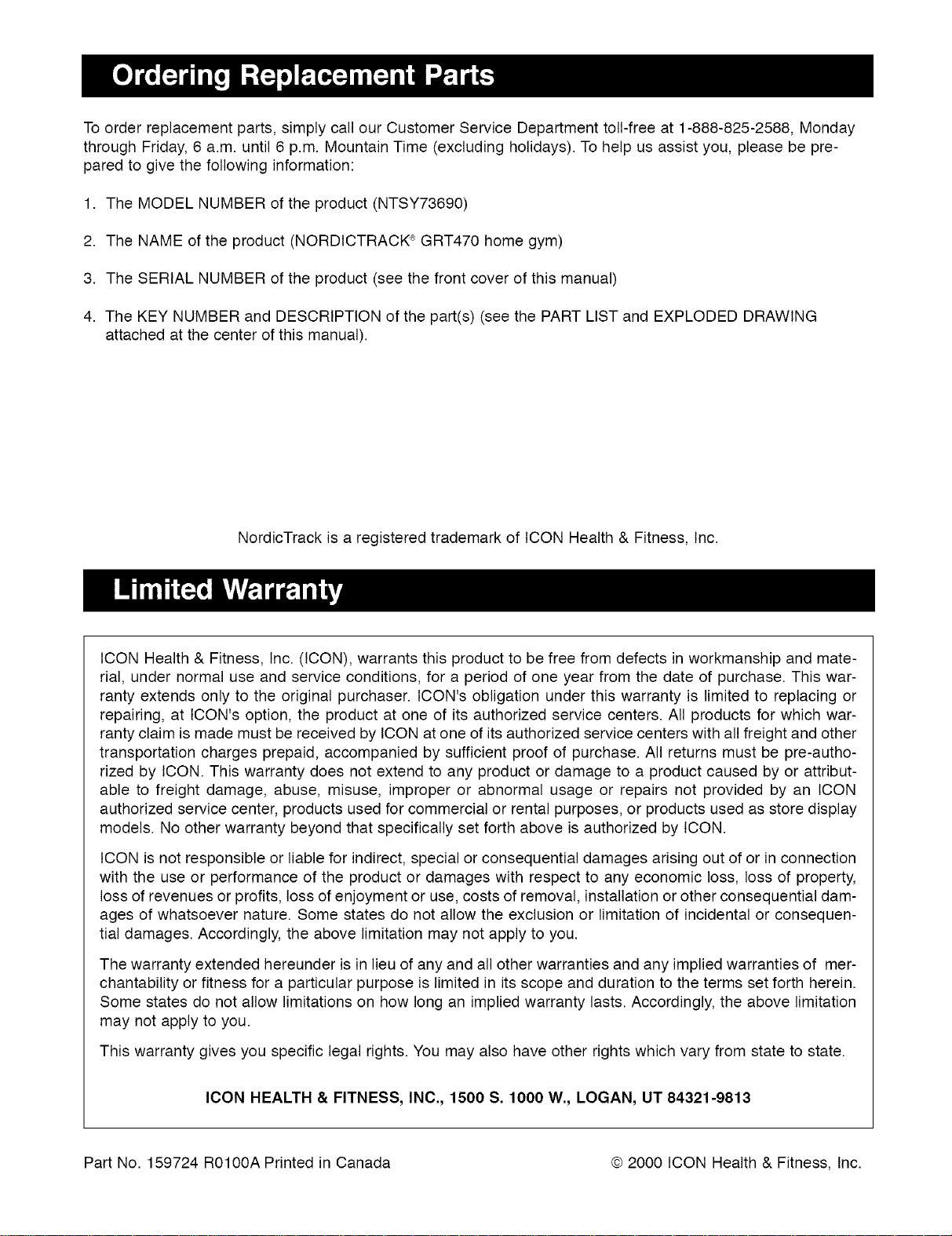
To order replacement parts, simply call our Customer Service Department toll-free at 1-888-825-2588, Monday
through Friday, 6 a.m. until 6 p.m. Mountain Time (excluding holidays). To help us assist you, please be pre-
pared to give the following information:
1. The MODEL NUMBER of the product (NTSY73690)
2. The NAME of the product (NORDICTRACK '_;GRT470 home gym)
3. The SERIAL NUMBER of the product (see the front cover of this manual)
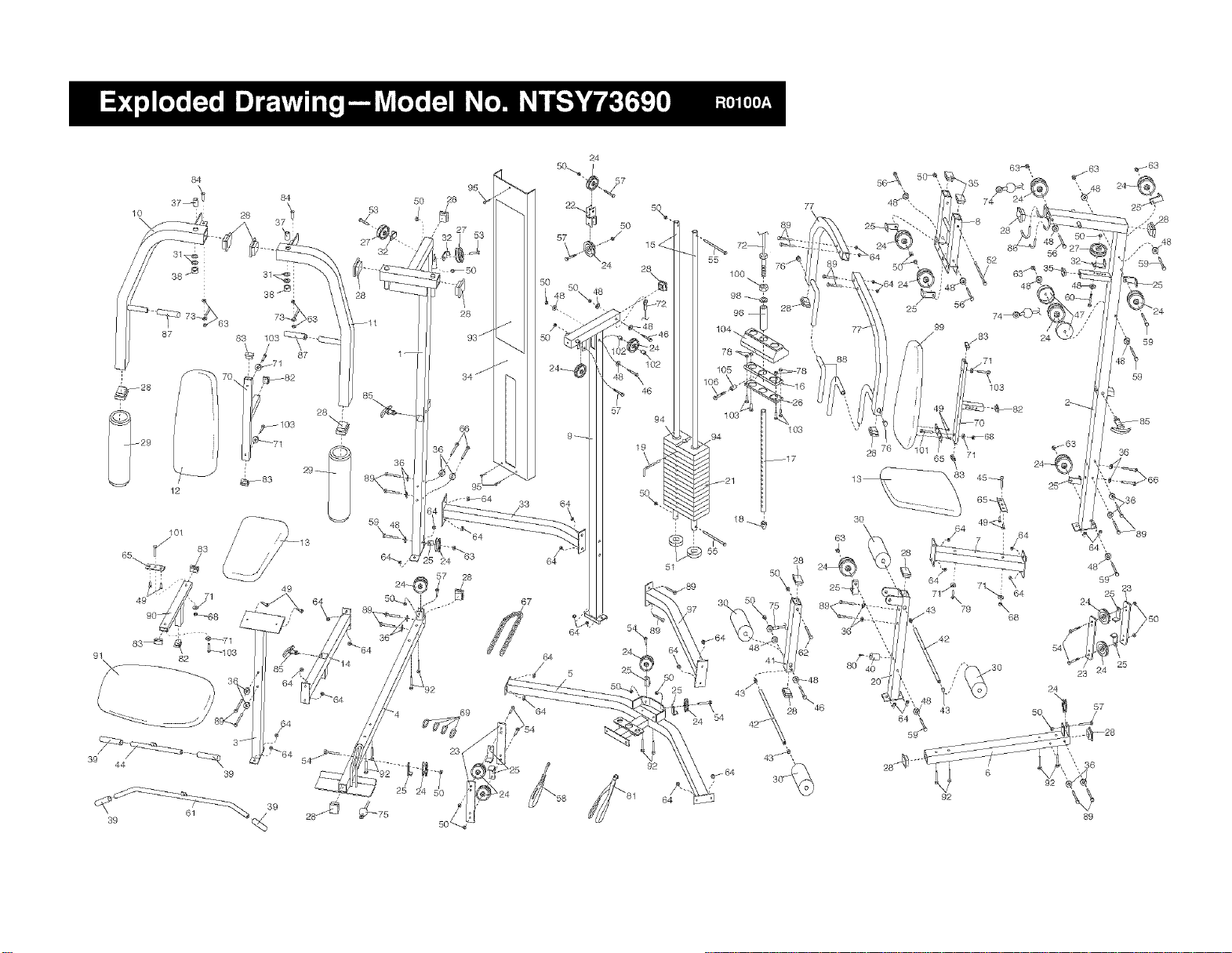
4. The KEY NUMBER and DESCRIPTION of the part(s) (see the PART LIST and EXPLODED DRAWING
attached at the center of this manual).
NordicTrack is a registered trademark of ICON Health & Fitness, Inc.
ICON Health & Fitness, Inc. (ICON), warrants this product to be free from defects in workmanship and mate-
rial, under normal use and service conditions, for a period of one year from the date of purchase. This war-
ranty extends only to the original purchaser. ICON's obligation under this warranty is limited to replacing or
repairing, at ICON's option, the product at one of its authorized service centers. All products for which war-
ranty claim is made must be received by ICON at one of its authorized service centers with all freight and other
transportation charges prepaid, accompanied by sufficient proof of purchase. All returns must be pre-autho-
rized by ICON. This warranty does not extend to any product or damage to a product caused by or attribut-
able to freight damage, abuse, misuse, improper or abnormal usage or repairs not provided by an ICON
authorized service center, products used for commercial or rental purposes, or products used as store display
models. No other warranty beyond that specifically set forth above is authorized by ICON.
ICON is not responsible or liable for indirect, special or consequential damages arising out of or in connection
with the use or performance of the product or damages with respect to any economic loss, loss of property,
loss of revenues or profits, loss of enjoyment or use, costs of removal, installation or other consequential dam-
ages of whatsoever nature. Some states do not allow the exclusion or limitation of incidental or consequen-
tial damages. Accordingly, the above limitation may not apply to you.
The warranty extended hereunder is in lieu of any and all other warranties and any implied warranties of mer-
chantability or fitness for a particular purpose is limited in its scope and duration to the terms set forth herein.
Some states do not allow limitations on how long an implied warranty lasts. Accordingly, the above limitation
may not apply to you.
This warranty gives you specific legal rights. You may also have other rights which vary from state to state.
ICON HEALTH & FITNESS, INC., 1500 S. 1000 W., LOGAN, UT 84321-9813
Part No. 159724 ROIOOA Printed in Canada © 2000 ICON Health & Fitness, Inc.