Loading ...
Loading ...
Loading ...
20
NOTE:
These conversions should only be carried out by
qualified persons. All connections must be
checked for gas leaks before re-commissioning
the appliance.
Adjustment of components that have
adjustments / settings sealed (e.g. paint sealed)
can only be adjusted in accordance with the
following instructions and shall be re-sealed
before re-commissioning this appliance.
For all relevant gas specifications refer to the
table at the end of this section.
1. Turn ‘Off’ the gas
supply at the main
supply.
2. Remove pot stands
from top of the
appliance, taking
note that pot stands
are manufactured with a lip on one edge, the lip
must always be fitted to outer edge (front and
back) of the cooktop.
3. Remove burner caps and burners (these are a
loose fit to the cook top) from top of cooktop,
(On Pilot / Flame Failure units, take care not to
damage the thermocouple which is fitted to the
mounting bracket / rail. Fitted as standard for UK
Market and optional for Non - UK Markets).
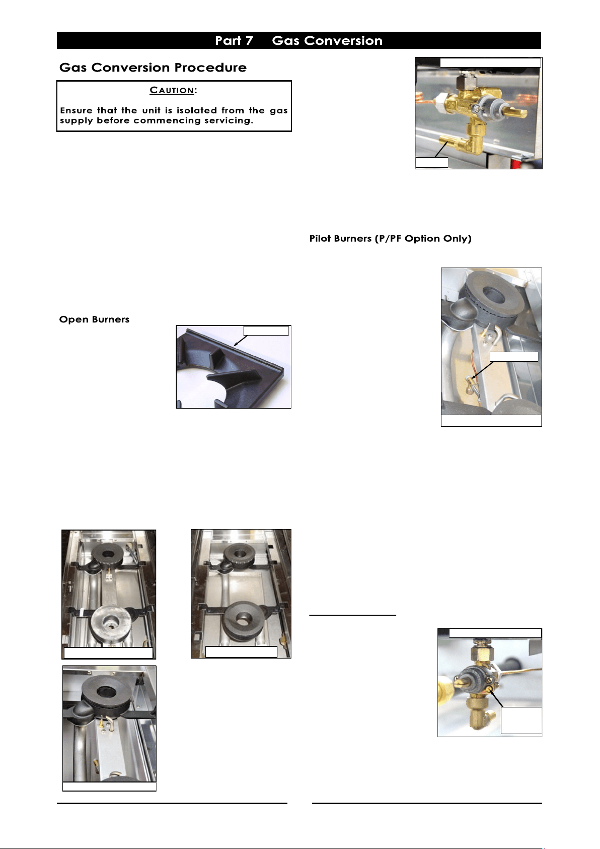
4. Unscrew and
remove injectors (½"
A/F) from the gas
valves.
5. Determine correct
injector sizes for the
corresponding gas
from the rating
plate attached to
the underside of the
right hand side, front Cooktop lower trim.
6. Replace with the correct size injectors. Refer to
the ‘Gas Specifications' table at the rear of this
section, for correct injector sizes.
1. Remove the pot stands as shown earlier.
2. Unscrew and remove the
pilot injector for each
burner, from beneath the
mounting rails.
3. Determine the correct
pilot injector sizes for the
corresponding gas from
the rating plate which is
attached to underside of
the front right hand side,
cooktop lower trim.
4. Replace with correct size
pilot injectors. Refer to
the ‘Gas Specifications'
table at rear of this
manual, for correct injector sizes.
5. Turn on the gas supply at the mains, re-light the
burners and check the flame size on the simmer
(LOW) position.
NOTE:
The right hand gas control valve supplies the rear
burner and the left hand gas control valve supplies
the front burner.
6. Refit pot stands to top of the appliance, taking
note that the pot stands are manufactured with
a lip on one edge, the lip must always be fitted
to outer edge (front and back) of the cooktop.
Low Fire Adjustment
a. To adjust the open burner
low fire adjustment,
remove the gas control
knobs from the front of
the control panel.
b. Adjust the low fire
adjustment screw on the
open burner gas control
valves to obtain the
desired flame size.
NOTE:
The 'Low Fire Screw' should be sealed with coloured
paint on completion of the low fire adjustment.
Standard Burners
Flame Failure Burners
Flame Failure Valve Shown
Injector
Pilot Injector
Pilot / Flame Failure Burners
Low Fire
Adjustment
Screw
Flame Failure Valve Shown
Pot Stand Lip
Pilot / Flame Failure Burners
Loading ...
Loading ...
Loading ...