Loading ...
Loading ...
Loading ...
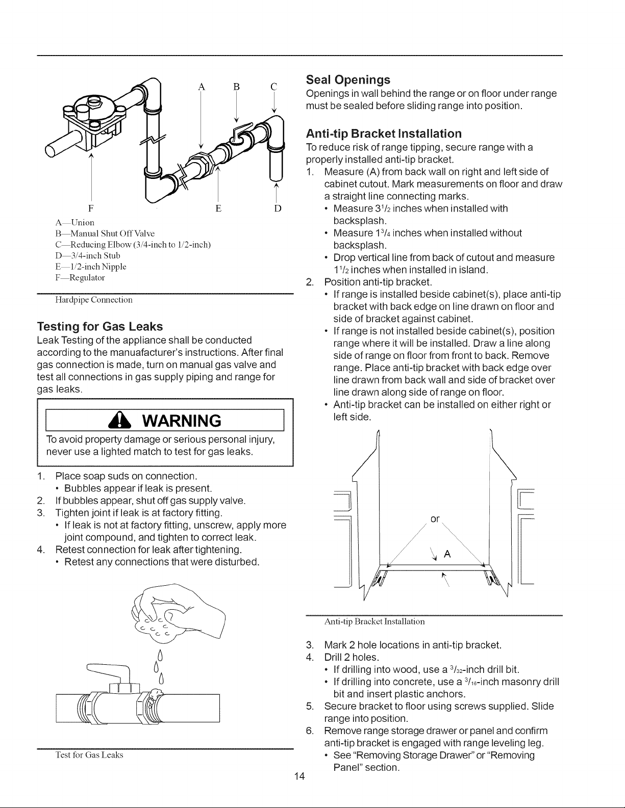
A B C
F
_Union
B_anual Shut OffValve
C_educing Elbow (3/4-inch to l/2-inch)
D 3/4-inch Stub
E 1/2-inch Nipple
F Regulator
E
Hardpipe Connection
Testing for Gas Leaks
Leak Testing of the appliance shall be conducted
according to the manuafacturer's instructions. After final
gas connection is made, turn on manual gas valve and
test all connections in gas supply piping and range for
gas leaks,
WARNING
To avoid property damage or serious personal injury,
never use a lighted match to test for gas leaks.
Place soap suds on connection.
• Bubbles appear if leak is present.
2. If bubbles appear, shut off gas supply valve.
3. Tighten joint if leak is at factory fitting.
• If leak is not at factory fitting, unscrew, apply more
joint compound, and tighten to correct leak.
4. Retest connection for leak after tightening.
• Retest any connections that were disturbed.
Seal Openings
Openings in wall behind the range or on floor under range
must be sealed before sliding range into position.
Anti=tip Bracket Installation
To reduce risk of range tipping, secure range with a
properly installed anti-tip bracket.
1. Measure (A) from back wall on right and left side of
cabinet cutout. Mark measurements on floor and draw
a straight line connecting marks.
• Measure 31/2inches when installed with
backsplash.
• Measure 13/4inches when installed without
backsplash.
• Drop vertical line from back of cutout and measure
1_/2inches when installed in island.
2. Position anti-tip bracket.
• If range is installed beside cabinet(s), place anti-tip
bracket with back edge on line drawn on floor and
side of bracket against cabinet.
• If range is not installed beside cabinet(s), position
range where it will be installed. Draw a line along
side of range on floor from front to back. Remove
range. Place anti-tip bracket with back edge over
line drawn from back wall and side of bracket over
line drawn along side of range on floor.
• Anti-tip bracket can be installed on either right or
left side.
or
\\\\\
/ \ A
i
Test for Gas Leaks
14
Anti-tip Bracket Installation
3. Mark 2 hole locations in anti-tip bracket.
4. Drill 2 holes.
• If drilling into wood, use a 3/32-inchdrill bit.
• If drilling into concrete, use a 3/16-inchmasonry drill
bit and insert plastic anchors.
5. Secure bracket to floor using screws supplied. Slide
range into position.
6. Remove range storage drawer or panel and confirm
anti-tip bracket is engaged with range leveling leg.
• See "Removing Storage Drawer" or "Removing
Panel" section.
Loading ...
Loading ...
Loading ...