Loading ...
Loading ...
Loading ...
69-2715EF—07 6
Installing your thermostat
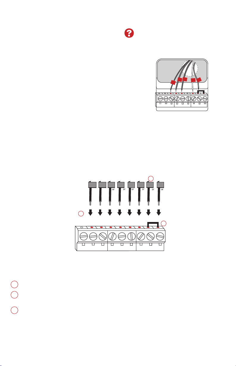
Wiring (heat pump system only)
7B Wire thermostat to your heat pump.
a Starting with the C Wire, match the sticky tag on the wire to the terminal
labels.
You must have a C wire.
b Loosen screw, insert wire on inside edge
of terminal, then tighten screw.
c Verify wire is firmly secured by gently
pulling on wire.
d Repeat steps a–c for all other wires.
e Push any excess wire back into the wall
opening after all wires are installed.
f
Continue to page 8.
Note: If old thermostat has separate wires on AUX and
E, place both wires into the E/AUX terminal.
If old thermostat has wire on AUX with a jumper to E,
place wire on E/AUX terminal. No jumper is required.
Labels don’t match? See alternate
wiring key on pages 7.
MCR33877
G
O
Y
R
HEAT PUMP
AUX/E
G O/B
YRRCK
L
C
Aux
Note: The wiring for your
application might be
different from the wiring
shown above.
Alternate wiring (conventional system)
Use this if your wire labels don’t match the terminal labels.
Note: You must have
a C wire or equivalent.
Do not use K terminal. For future use.
If your old thermostat had both R and RH wires, remove metal jumper.
Connect the R wire to the RC terminal, and the RH wire to the R terminal.
Remove metal jumper connecting R and RC only if you must connect both
R and RC.
Alternate wiring key (conventional system)
2
3
1
Y2
R
4M
V
RHY1
H
W1F
RYWG
RC
W2
W2
G W
YRRC
Y2
C
MCR33885
CONVENTIONAL
C
B
C1
X
K
1
2
3
Loading ...
Loading ...
Loading ...