Loading ...
Loading ...
Loading ...
69-2715EF—07 18
Setting functions and options
You can change options for a number of system functions. Available functions depend
on the type of system you have. The functions, along with available options, are
described on pages 1819.
This thermostat is pre-set for a single-stage heating/cooling system. Setting function
1 for a heat pump will adjust the default settings.
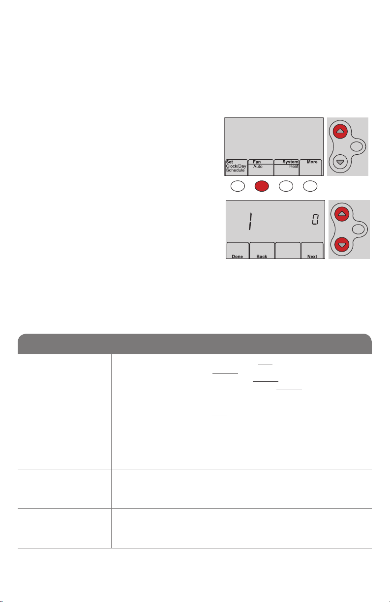
1 Press Fan and s simultaneously and hold
for approximately 3 seconds. The screen
will change to display two numbers and
the button designations will be Done, Back,
blank, Next.
2 Press Next until you see the function
number—the larger number on the left—
you want to set.
3 Change options for any function by
pressing s or t until the correct option
(smaller number on right) is displayed.
4 Repeat Steps 2 and 3 until you have set all
functions that you wish to change.
5 When you have made all changes, press
Done to save and exit.
HOLD
MCR33883
MCR33884
HOLD
System setup
Function Settings & Options
1
Select System
Type
If you are not sure
of your heating/
cooling system
type or have other
questions, go to
honeywellhome.
com
0 Heat/cool: Gas, oil or electric heating with central air conditioning.
1 Heat pump: Heat pump without backup or auxiliary heat.
2 Heat only: Gas, oil or hot water heat without central air conditioning.
3 Heat only with fan: Gas, oil or electric heat without central air
conditioning.
4 Cool only: Central air conditioning only.
5 Heat pump: Heat pump with backup or auxiliary heating.
6 Heat/Cool Multiple stages: 2 heat stages (wires on W and W2), 2
cooling stages (wires on Y and Y2).
7 Heat/Cool Multiple stages: 2 heat stages (wires on W and W2), 1
cooling stage (wire on Y).
8 Heat/Cool Multiple stages: 1 heat stage (wires on W), 2 cooling
stages (wire on Y and Y2).
2
Heat Pump
Changeover Valve
(for heat pumps
only)
0 Cooling changeover valve: Use this setting if you connected a wire
labeled “O” to the O/B terminal.
1 Heating changeover valve: Use this setting if you connected a wire
labeled “B” to the O/B terminal.
3
Heating Fan
Control
0 Gas or oil heat: Use this setting if you have a gas or oil heating system
(system controls fan operation).
1 Electric heat: Use this setting if you have an electric heating system
(thermostat controls fan operation).
Loading ...
Loading ...
Loading ...