Loading ...
Loading ...
Loading ...
37
INSTALLATION INSTRUCTIONS
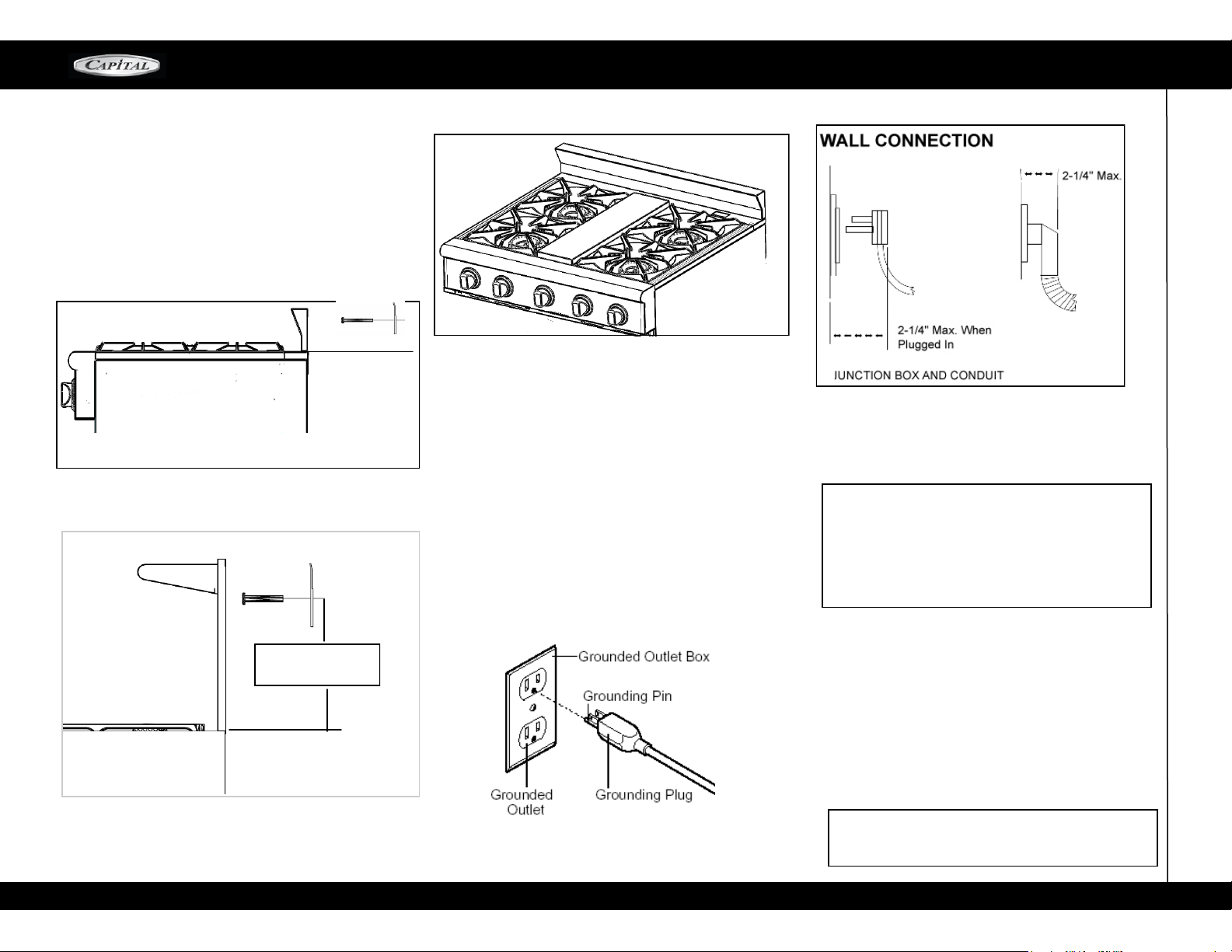
WARNING! The third prong SHOULD NOT, under
any circumstances, be cut or removed!
GROUNDING METHOD
The range is factory fitted with a power supply and
cord with a three-prong grounding plug. It must be
plugged into a matching grounding type receptacle
c o n n ec t e d t o a c or re c t ly p o l ar iz e d 12 0 V olt
circuit. If the circuit does not have a grounding type
receptacle, it is the responsibility of the installer to
have the existing receptacle changed to a properly
grounded and polarized receptacle in accordance
with all applicable local codes and ordinances. The
receptacle replacement shall be in accordance with
the national Electrical Code.
CAUTION! Disconnect the electrical supply cord
from the wall outlet before servicing the range.
Follow all governing codes and ordinances when
grounding. In the absenc e of codes follow the
National Electrical Codes ANSI / NFP A No. 70
(current issue).
30" Range – 7 Amps. Max.
36" Range – 7 Amps. Max.
48" Range – 15.5 Amps. Max.
60" Range not available in LMCR series of Ranges
ELECTRICAL SUPPLY, ALL RANGES
I n s tal lat io n of Al l M CR r a ng e s m ust be
planned so that the rough-in of the junction box
for the receptacle or conduit connection allows for
maximum clearance to the rear of the unit.
This is especially critical if the junction box in the
wall is directl y behind the junction box of the
unit when the unit is installed. To minimize binding
when the unit is connected to the receptacle or
junc t ion bo x, orient the receptac le or condui t
connector, and slide back into position.
POWER REQUIREMENTS: 120VAC, 60 HZ single phase
NOTE:
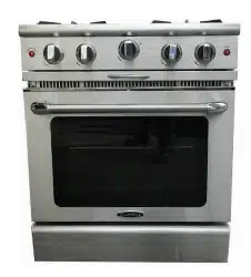
ALL MCR-SERIES RANGES Are provided with 3” Back
Guard.
1. For 6” Secure both Brackets to the wall using
the screws included. 4-7/16” from the Back Trim sur-
face to the center of hole of Bracket. see Fig-1
2. For Low Back & High Shelf Accessories. see Fig-2.
MCOR-SERIES
Fig-1
Fig-3
Fig-2
16-3/8” For High
Shelf
Loading ...
Loading ...
Loading ...