Loading ...
Loading ...
Loading ...
Operation Basics
USER’S MANUAL 27
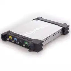
2.6 Input Connectors
CH1/CH2/CH3/CH4: Input connectors for waveform display.
LOGIC IN:Logic analyzer input ports
LOGIC OUT:Digital generator output ports
1KHz~1Vp-p:1KHz, 1Vp-p Square wave output ports
GND.: A ground terminal
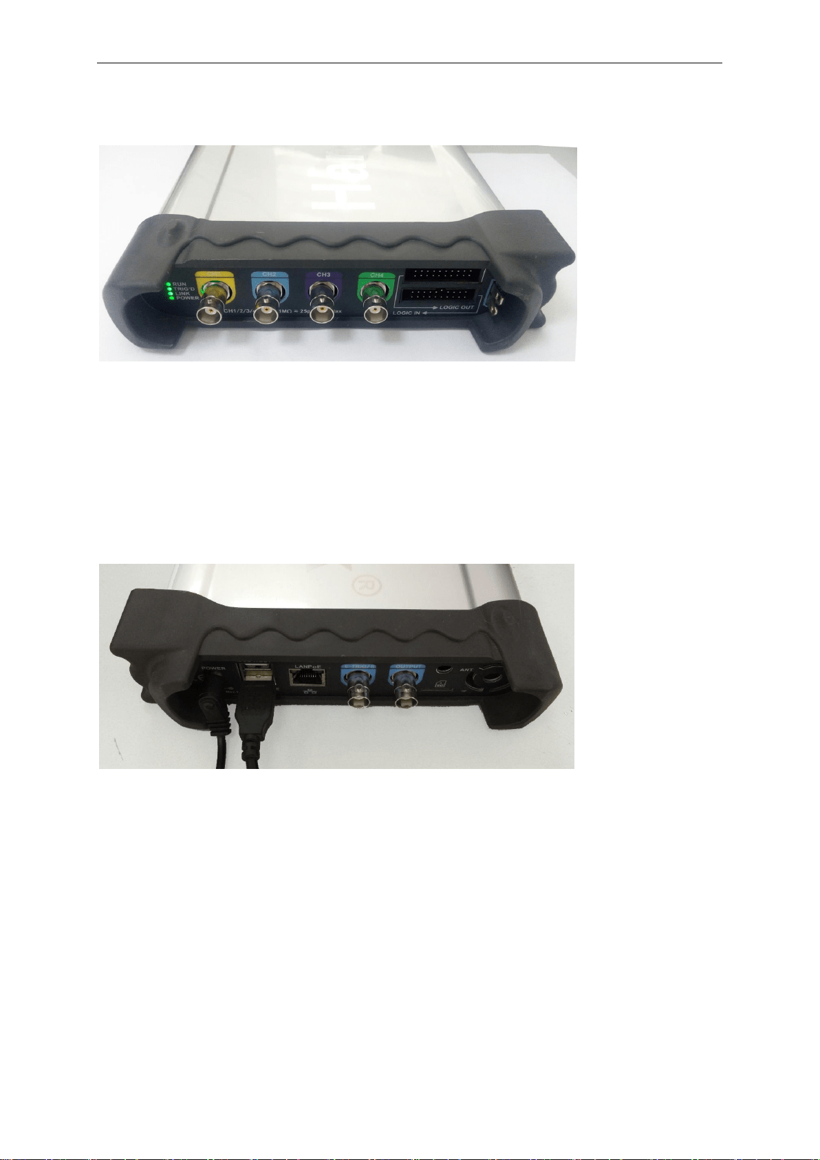
Other Connector:
Power: Power Input port.
USB HOST: USB HOST port, used to insert into USB storage device.
USB DEVICE: USB port, used to connect the scope with PC via USB cable.
LANPoE: Power Over Ethernet port, used to connect the scope with PC via LAN and power over
ethernet.
SD: MicroSD port, used to insert into microSD card to storage data.
OUTPUT: Waveform output BNC port in waveform generator mode.
E-TRIG/S:
1.E-TRIG: External trigger signal port (For the model of waveform generator function, it can be
used as an external trigger of the oscilloscope and waveform generator.)
2.S: Synchronized output port (Only for the model with waveform generator function.)
Attention: The above two functions cannot be used at the same time. When one function is used,
the other function is automatically closed.
Loading ...
Loading ...
Loading ...