
Loading ...
Loading ...
Loading ...
10
SET-UP
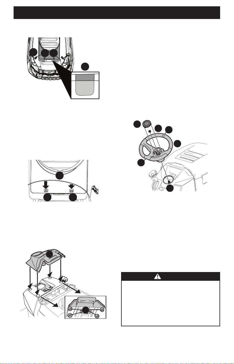
2. With the rear tabs installed, insert the front tabs (a) on the
plenum (b) (Figure 11).
a
b
aa
Figure 11
NOTE: The rear tabs fit into a recessed area on the top of
the hood. They slide up from under the hood and into these
recessed areas.
3. Push up on the bottom of the plenum to make sure that the
plenum is securely in place.
4. Secure the headlight harness (a) into the two guides (b) on
the front of the plenum (Figure 12).
a
b b
Figure 12
Installing the Dash Cap (If necessary)
To install the dash cap (a), line up the tabs (b) on the dash cap (a)
with the holes in the upper dash (Figure 13). Slide the tabs (b)
into the holes in the upper dash and push forward on the dash
cap to lock into place.
a
b
Figure 13
NOTE: Be sure to press on the lower part of the dash cap (a)
facing the operator position to ensure the lower tabs on the dash
cap are in place (Figure 13).
Installing the Steering Wheel (If necessary)
The hardware for attaching the steering wheel has been packed
within the steering wheel, beneath the steering wheel cap.
Carefully remove the cover by inserting a small flat screwdriver
into one of the three snap locations, and slowly prying up on the
steering wheel cap to remove the hardware.
IMPORTANT! Do not use impact tools to install or remove
the steering wheel. Doing so can over-torque and damage
the fastener.
1. With the wheels of the tractor pointing straight forward,
align the steering wheel (a) by using the center-line (b) on
the front of the steering wheel (a) pointing straight ahead
and the flat section (c) of the steering wheel (a) facing toward
the seat, place the steering wheel (a) over the steering shaft
(d) (Figure 14).
a
d
e
f
b
c
Figure 14
2. Secure the steering wheel (a) with the hex bolt (e) from under
the steering wheel cap (f) and torque to 18-22 ft-lbs (24-30
N-m) (Figure 14).
3. Place the steering wheel cap (f) over the center of the
steering wheel (a) and push downward until it “clicks” into
place (Figure 14).
NOTE: The hex bolt (e) securing the steering wheel (a) has thread
locker applied to it, so if it is removed, it is recommended that the
hex bolt (e) be replaced or thread lock re-applied (Figure 14).
Installing the Front Bumper (If equipped)
WARNING
Disengage the PTO, engage the brake lock, and stop
the tractor engine before performing any preparation
procedures. Place the tractor on a firm and level surface
before beginning installation or removal procedures.
The exhaust system and surrounding areas are HOT. To
avoid personal injury, allow the tractor to cool before
beginning any installation or removal procedures.
The hardware for attaching the front bumper is shipped installed
into the bumper.
Loading ...
Loading ...
Loading ...