Home
Bookmarks
Home
Siglent
Siglent SDS2000X User Manual
Page 105
Siglent SDS2000X Hd Digital Storage Oscilloscope
User Manual - Page 105
For SDS2000X.
PDF File Manual
,
250 pages
,
Read Online
|
Download pdf file
Copyright and Declaration
Safety Information
General Safety Summary
Safety Terms and Symbols
Measurement Category
Working Environment
Ventilation Requirement
General Care and Cleaning
Exigence de Sécurité
Termes et symboles de sécurité
Définition des catégories de mesure
Conditions d’utilisation
Condition de ventilation
Entretien et nettoyage
Document Overview
Quick Start
General Inspection
Appearance and Dimensions
To Prepare the Oscilloscope for Use
To Adjust the Supporting Legs
To Connect to Power Supply
Power-on Inspection
To Connect the Probe
Functional Inspection
Probe Compensation
The Front Panel
The Rear Panel
Front Panel Function Overview
Horizontal
Vertical
Trigger
Run Control
Universal Knob
Menu
Help
User Interface
To Use the Security Lock
To Set the Vertical System
To Enable the Channel
To Adjust the Vertical Scale
To Adjust the Vertical Position
To Specify Channel Coupling
To Specify Bandwidth Limit
To Specify Probe Attenuation Factor
To Specify channel Input Impedance
To Specify Amplitude Unit
To Invert a Waveform
Set the Horizontal System
Adjust the Horizontal Scale
Adjust Trigger Delay
Set the Roll mode
Use the Zoom Function
To Set the Sample System
Run Control
Overview of Sampling
Sampling Theory
Sample Rate
Oscilloscope Bandwidth and Sample Rate
To Specify Memory Depth
To Select Sampling Mode
To Select Waveform Interpolation Method
To Select Acquisition Mode
Normal
Peak Detect
Average
Eres (Enhanced Resolution)
To Change the Horizontal Format
Use Sequence Mode
To Trigger the Oscilloscope
Trigger Source
Trigger Mode
Trigger Level
Trigger Coupling
Trigger Holdoff
Noise Rejection
Trigger Type
Edge Trigger
Slope Trigger
Pulse Trigger
Video Trigger
Window Trigger
Interval Trigger
DropOut Trigger
Runt Trigger
Pattern Trigger
Serial trigger and decode
IIC Trigger and Serial Decode
Setup for IIC Signals
IIC Triggering
To introduce the trigger conditions
Operation steps:
IIC Serial Decode
Interpreting IIC Decode
SPI Triggering and Serial Decode
Setup for SPI Signals
SPI Triggering
SPI Serial Decode
Interpreting SPI Decode
UART/RS232 Trigger and Serial Decode
Setup for UART/RS232 Signals
UART/RS232 Triggering
UART/RS232 Serial Decode
Interpreting UART/RS232 Decode
CAN Trigger and Serial Decode
Setup for CAN Signals
CAN Triggering
To introduce the trigger conditions
Operation steps:
CAN Serial Decode
Interpreting CAN Decode.
LIN Triggering and Serial Decode
Setup for LIN Signals
LIN Triggering
To introduce the trigger conditions
Operation steps:
LIN Serial Decode
Interpreting LIN Decode
Digital Channels
To Connect the Digital Probes to the Device-under-test
Acquiring Waveform Using the Digital Channels
To Change the Display Type of the Digital Channels
To Switch a Single Channel On or Off
To Switch All Digital Channels On or Off
To Change the Logic Threshold for Digital Channels
To Reposition a Digital Channel
To Display Digital Channels as a Bus
To Save Reference Waveform
To Save REF Waveform to Internal Memory
To Display REF Waveform
To Adjust REF Waveform Display
To Clear REF Waveform Display
To Use the Math Operation
Units for Math Waveforms
Math Operators
Addition or Subtraction
Multiplication and Division
FFT Operation
Differentiate
Integrate
Square Root
To Adjust the Math Waveform Scale and Offset
To Adjust the Math Waveform Horizontal Scale and Offset
To Adjust the Math Waveform Vertical Scale and Offset
To Make Cursor Measurements
X Cursors
Y Cursors
To Make Cursor Measurements
To Make Measurements
Type of Measurement
Voltage Measurements
Time Measurements
Delay Measurements
To Make Automatic Measurements
To Clear Measurement Parameters
To Make All Measurement
Display Setting
To Set Display Type
To Set Color Display
To Set and Clear Persistence
To Clear the Display
To Select Grid Type
To Adjust Waveform Intensity
To Adjust Grid Brightness
To Adjust Transparence
Save and Recall
Save Type
Internal Save and Recall
External save and recall
Disk Management
To Create a New File or Folder
To delete a file or folder
To rename a file or a folder
System Function Setting
To View the System Status
To Do Self-Calibration
To Enable or Disable the Sound
To Specify the Language
To Enable Pass/Fail Test
To Set and Perform Pass/Fail Test
To Save and Recall Test Mask
I/O Set
To Set the USB Device
To Set the LAN
To Set Aux Output
To Do Power Analysis
To Perform Channel Deskew
Perform Power Analysis
To Enable Quick-Cal
To Update Firmware and Configuration
To Perform a Self-Test
Screen Test
Keyboard Test
LED Test
To Specify the Screen Saver Time
Option Management
To Use the History Function
Arbitrary Waveform Generator
To Set Wave Type and Parameters
To Output Arbitrary Waveform
To Set Output Load
Recover the Default Setup of AWG.
To Do AWG Self-Cal
Default Setup
Troubleshooting
Page 105/250
Page 1
Page 2
Page 3
Page 4
Page 5
Page 6
Page 7
Page 8
Page 9
Page 10
Page 11
Page 12
Page 13
Page 14
Page 15
Page 16
Page 17
Page 18
Page 19
Page 20
Page 21
Page 22
Page 23
Page 24
Page 25
Page 26
Page 27
Page 28
Page 29
Page 30
Page 31
Page 32
Page 33
Page 34
Page 35
Page 36
Page 37
Page 38
Page 39
Page 40
Page 41
Page 42
Page 43
Page 44
Page 45
Page 46
Page 47
Page 48
Page 49
Page 50
Page 51
Page 52
Page 53
Page 54
Page 55
Page 56
Page 57
Page 58
Page 59
Page 60
Page 61
Page 62
Page 63
Page 64
Page 65
Page 66
Page 67
Page 68
Page 69
Page 70
Page 71
Page 72
Page 73
Page 74
Page 75
Page 76
Page 77
Page 78
Page 79
Page 80
Page 81
Page 82
Page 83
Page 84
Page 85
Page 86
Page 87
Page 88
Page 89
Page 90
Page 91
Page 92
Page 93
Page 94
Page 95
Page 96
Page 97
Page 98
Page 99
Page 100
Page 101
Page 102
Page 103
Page 104
Page 105
Page 106
Page 107
Page 108
Page 109
Page 110
Page 111
Page 112
Page 113
Page 114
Page 115
Page 116
Page 117
Page 118
Page 119
Page 120
Page 121
Page 122
Page 123
Page 124
Page 125
Page 126
Page 127
Page 128
Page 129
Page 130
Page 131
Page 132
Page 133
Page 134
Page 135
Page 136
Page 137
Page 138
Page 139
Page 140
Page 141
Page 142
Page 143
Page 144
Page 145
Page 146
Page 147
Page 148
Page 149
Page 150
Page 151
Page 152
Page 153
Page 154
Page 155
Page 156
Page 157
Page 158
Page 159
Page 160
Page 161
Page 162
Page 163
Page 164
Page 165
Page 166
Page 167
Page 168
Page 169
Page 170
Page 171
Page 172
Page 173
Page 174
Page 175
Page 176
Page 177
Page 178
Page 179
Page 180
Page 181
Page 182
Page 183
Page 184
Page 185
Page 186
Page 187
Page 188
Page 189
Page 190
Page 191
Page 192
Page 193
Page 194
Page 195
Page 196
Page 197
Page 198
Page 199
Page 200
Page 201
Page 202
Page 203
Page 204
Page 205
Page 206
Page 207
Page 208
Page 209
Page 210
Page 211
Page 212
Page 213
Page 214
Page 215
Page 216
Page 217
Page 218
Page 219
Page 220
Page 221
Page 222
Page 223
Page 224
Page 225
Page 226
Page 227
Page 228
Page 229
Page 230
Page 231
Page 232
Page 233
Page 234
Page 235
Page 236
Page 237
Page 238
Page 239
Page 240
Page 241
Page 242
Page 243
Page 244
Page 245
Page 246
Page 247
Page 248
Page 249
Page 250
Contents
Table of Contents
Search
Previous
Next
Troubleshooting
Bookmarks
Loading ...
Loading ...
Loading ...
SIG
L
ENT
SDS2
0
00X User
M
anual
75
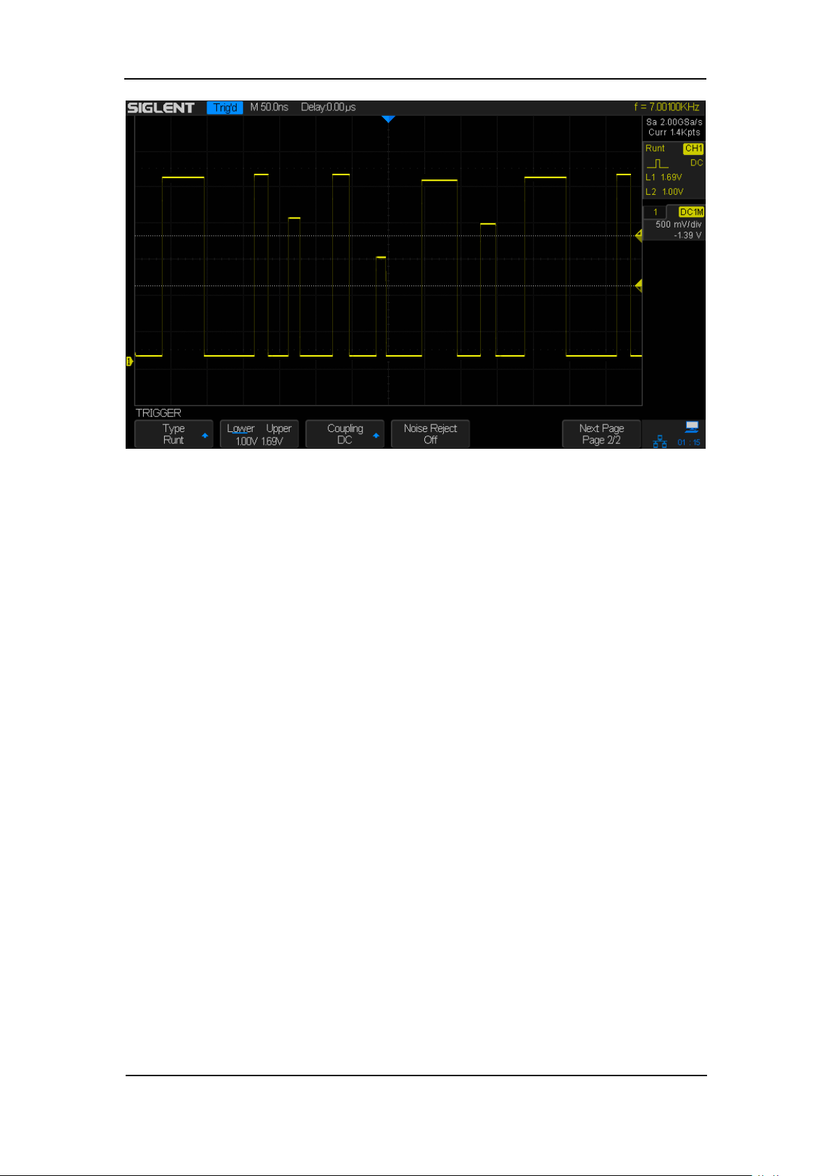
Figure
33
: Run
t T
rigger
Loading ...
Loading ...
Loading ...
File type: PDF
File name: 2050415_sds2000x.pdf
File size: 3.65 MB
File Language: English
Pages: 250
Author: Siglent
File created: 2023-04-07
Published: 2023-04-09
Updated: 2023-04-08
Download File
Table of Contents
×
Copyright and Declaration
3
Safety Information
4
General Safety Summary
4
Safety Terms and Symbols
6
Measurement Category
7
Working Environment
8
Ventilation Requirement
9
General Care and Cleaning
10
Exigence de Sécurité
11
Termes et symboles de sécurité
14
Définition des catégories de mesure
15
Conditions d’utilisation
16
Condition de ventilation
17
Entretien et nettoyage
18
Document Overview
19
Quick Start
31
General Inspection
32
Appearance and Dimensions
33
To Prepare the Oscilloscope for Use
34
To Adjust the Supporting Legs
34
To Connect to Power Supply
35
Power-on Inspection
36
To Connect the Probe
37
Functional Inspection
38
Probe Compensation
39
The Front Panel
40
The Rear Panel
41
Front Panel Function Overview
42
Horizontal
42
Vertical
43
Trigger
45
Run Control
46
Universal Knob
47
Menu
48
Help
49
User Interface
50
To Use the Security Lock
52
To Set the Vertical System
53
To Enable the Channel
54
To Adjust the Vertical Scale
55
To Adjust the Vertical Position
55
To Specify Channel Coupling
56
To Specify Bandwidth Limit
56
To Specify Probe Attenuation Factor
57
To Specify channel Input Impedance
57
To Specify Amplitude Unit
58
To Invert a Waveform
58
Set the Horizontal System
59
Adjust the Horizontal Scale
60
Adjust Trigger Delay
61
Set the Roll mode
62
Use the Zoom Function
63
To Set the Sample System
64
Run Control
65
Overview of Sampling
66
Sampling Theory
66
Sample Rate
67
Oscilloscope Bandwidth and Sample Rate
68
To Specify Memory Depth
69
To Select Sampling Mode
69
To Select Waveform Interpolation Method
70
To Select Acquisition Mode
72
Normal
72
Peak Detect
73
Average
74
Eres (Enhanced Resolution)
75
To Change the Horizontal Format
76
Use Sequence Mode
77
To Trigger the Oscilloscope
79
Trigger Source
81
Trigger Mode
82
Trigger Level
83
Trigger Coupling
84
Trigger Holdoff
85
Noise Rejection
86
Trigger Type
88
Edge Trigger
89
Slope Trigger
90
Pulse Trigger
92
Video Trigger
94
Window Trigger
97
Interval Trigger
100
DropOut Trigger
102
Runt Trigger
104
Pattern Trigger
106
Serial trigger and decode
108
IIC Trigger and Serial Decode
109
Setup for IIC Signals
109
IIC Triggering
111
To introduce the trigger conditions
111
Operation steps:
113
IIC Serial Decode
115
Interpreting IIC Decode
115
SPI Triggering and Serial Decode
117
Setup for SPI Signals
117
SPI Triggering
120
SPI Serial Decode
122
Interpreting SPI Decode
122
UART/RS232 Trigger and Serial Decode
124
Setup for UART/RS232 Signals
124
UART/RS232 Triggering
126
UART/RS232 Serial Decode
128
Interpreting UART/RS232 Decode
129
CAN Trigger and Serial Decode
130
Setup for CAN Signals
130
CAN Triggering
132
To introduce the trigger conditions
132
Operation steps:
132
CAN Serial Decode
134
Interpreting CAN Decode.
135
LIN Triggering and Serial Decode
136
Setup for LIN Signals
136
LIN Triggering
137
To introduce the trigger conditions
137
Operation steps:
137
LIN Serial Decode
139
Interpreting LIN Decode
139
Digital Channels
141
To Connect the Digital Probes to the Device-under-test
142
Acquiring Waveform Using the Digital Channels
143
To Change the Display Type of the Digital Channels
143
To Switch a Single Channel On or Off
145
To Switch All Digital Channels On or Off
145
To Change the Logic Threshold for Digital Channels
145
To Reposition a Digital Channel
146
To Display Digital Channels as a Bus
146
To Save Reference Waveform
148
To Save REF Waveform to Internal Memory
149
To Display REF Waveform
149
To Adjust REF Waveform Display
150
To Clear REF Waveform Display
150
To Use the Math Operation
151
Units for Math Waveforms
152
Math Operators
153
Addition or Subtraction
153
Multiplication and Division
154
FFT Operation
155
Differentiate
159
Integrate
160
Square Root
161
To Adjust the Math Waveform Scale and Offset
162
To Adjust the Math Waveform Horizontal Scale and Offset
162
To Adjust the Math Waveform Vertical Scale and Offset
162
To Make Cursor Measurements
163
X Cursors
163
Y Cursors
163
To Make Cursor Measurements
164
To Make Measurements
165
Type of Measurement
166
Voltage Measurements
166
Time Measurements
168
Delay Measurements
169
To Make Automatic Measurements
170
To Clear Measurement Parameters
172
To Make All Measurement
172
Display Setting
173
To Set Display Type
174
To Set Color Display
175
To Set and Clear Persistence
175
To Clear the Display
176
To Select Grid Type
177
To Adjust Waveform Intensity
177
To Adjust Grid Brightness
179
To Adjust Transparence
179
Save and Recall
180
Save Type
181
Internal Save and Recall
182
External save and recall
183
Disk Management
186
To Create a New File or Folder
187
To delete a file or folder
188
To rename a file or a folder
188
System Function Setting
189
To View the System Status
190
To Do Self-Calibration
191
To Enable or Disable the Sound
192
To Specify the Language
192
To Enable Pass/Fail Test
193
To Set and Perform Pass/Fail Test
194
To Save and Recall Test Mask
195
I/O Set
197
To Set the USB Device
197
To Set the LAN
198
To Set Aux Output
199
To Do Power Analysis
200
To Perform Channel Deskew
201
Perform Power Analysis
203
To Enable Quick-Cal
227
To Update Firmware and Configuration
228
To Perform a Self-Test
229
Screen Test
229
Keyboard Test
230
LED Test
231
To Specify the Screen Saver Time
232
Option Management
233
To Use the History Function
235
Arbitrary Waveform Generator
237
To Set Wave Type and Parameters
238
To Output Arbitrary Waveform
240
To Set Output Load
241
Recover the Default Setup of AWG.
241
To Do AWG Self-Cal
242
Default Setup
243
Troubleshooting
249
Search:
×
Search