Loading ...
Loading ...
Loading ...
22
bromic.com/heat
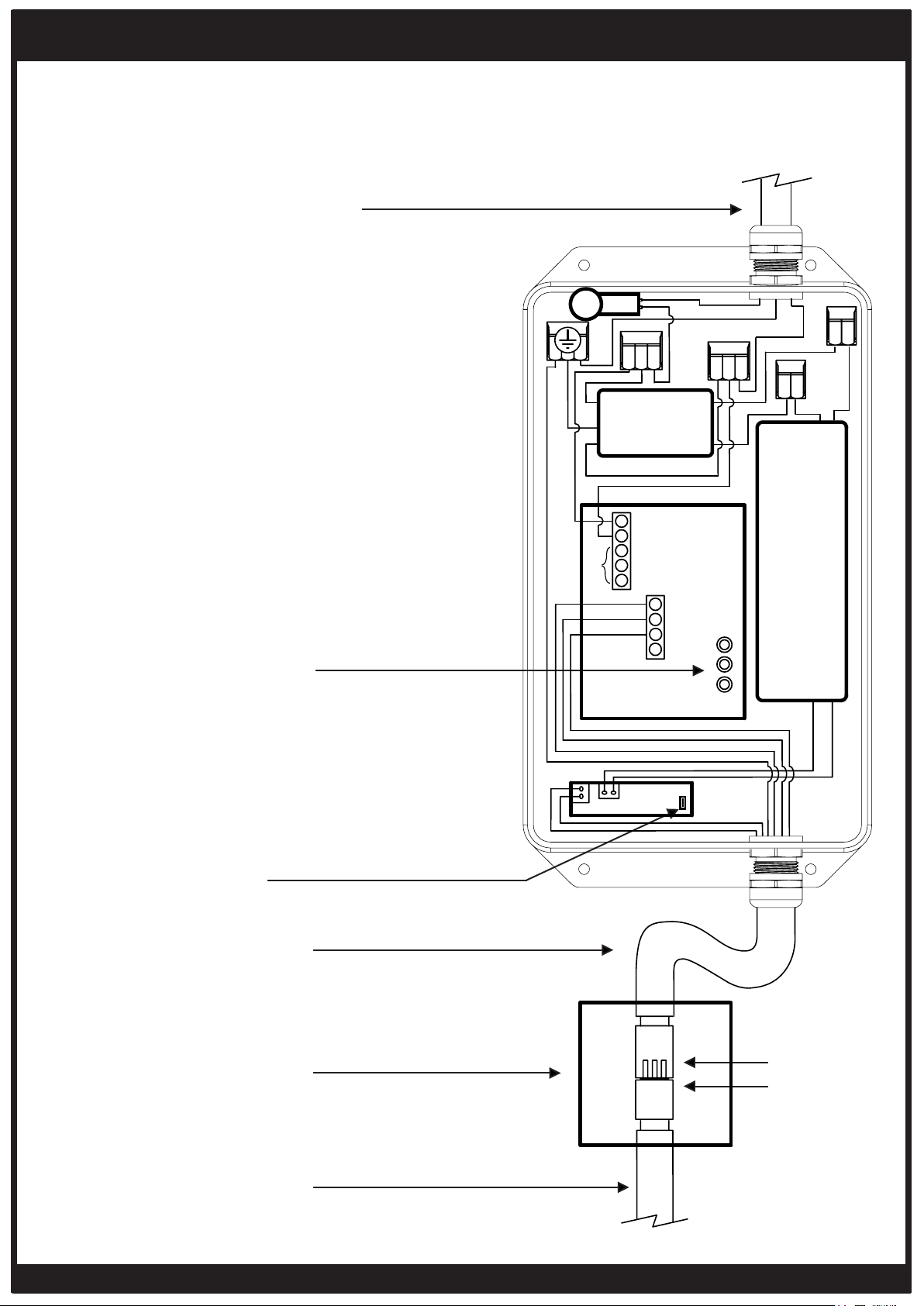
PORTABLE HEATER CONTROL WIRING DIAGRAM
NOTES:
- Supply connection must be protected
with appropriate safety device, that
includes isolation switch.
- Electrical installation must ensure
earth continuity is checked.
WIRING DIAGRAM
ONLY TO BE INSTALLED & SERVICED BY LICENSED & AUTHORIZED TECHNICIAN.
APPLIANCE MANUAL MUST BE READ BEFORE INSTALLING OR SERVICING THIS
PRODUCT.
Power cable from
controller (supplied with
heater base)
‘MEM’ button for re-
pairing remote to Heater
control PCB
Button for re-pairing
remote to LED PCB
Power supply 220-240V - a.c.
Minimum Circuit Ampacity 17A
(Supplied with heater base).
Small connector box
(supplied with heater
base)
6 core
connector
Power cable from heater
(supplied with heater
head)
TRANSFORMER
MEANWELL (LPF-25-24)
HEATER CONTROL PCB
EMI FILTER
(YB22D1-3A-W)
LED PCB DIMMER
DC OUT 24V
WHITE 24V DC
RED 24V DC
GREEN/YELLOW
GREEN/YELLOW
GROUND
GREY 240V
N/A
N/A
L
SET
DEL
MEM
L(N)
BLUE
L(N)
BLUE
BLUE
BLUE
BLUE
LINE
LOAD
NEUTRAL
LIVE
BROWN
BROWN
BROWN
BROWN
BROWN
BLACK 240V
L
G
G
G
L(N)
L
2
3
4
5
6
7
8
9
1
BLACK 24V DC
BROWN 24V DC
AC IN 240V
N
L
TILT
SWITCH
Loading ...
Loading ...
Loading ...