Loading ...
Loading ...
Loading ...
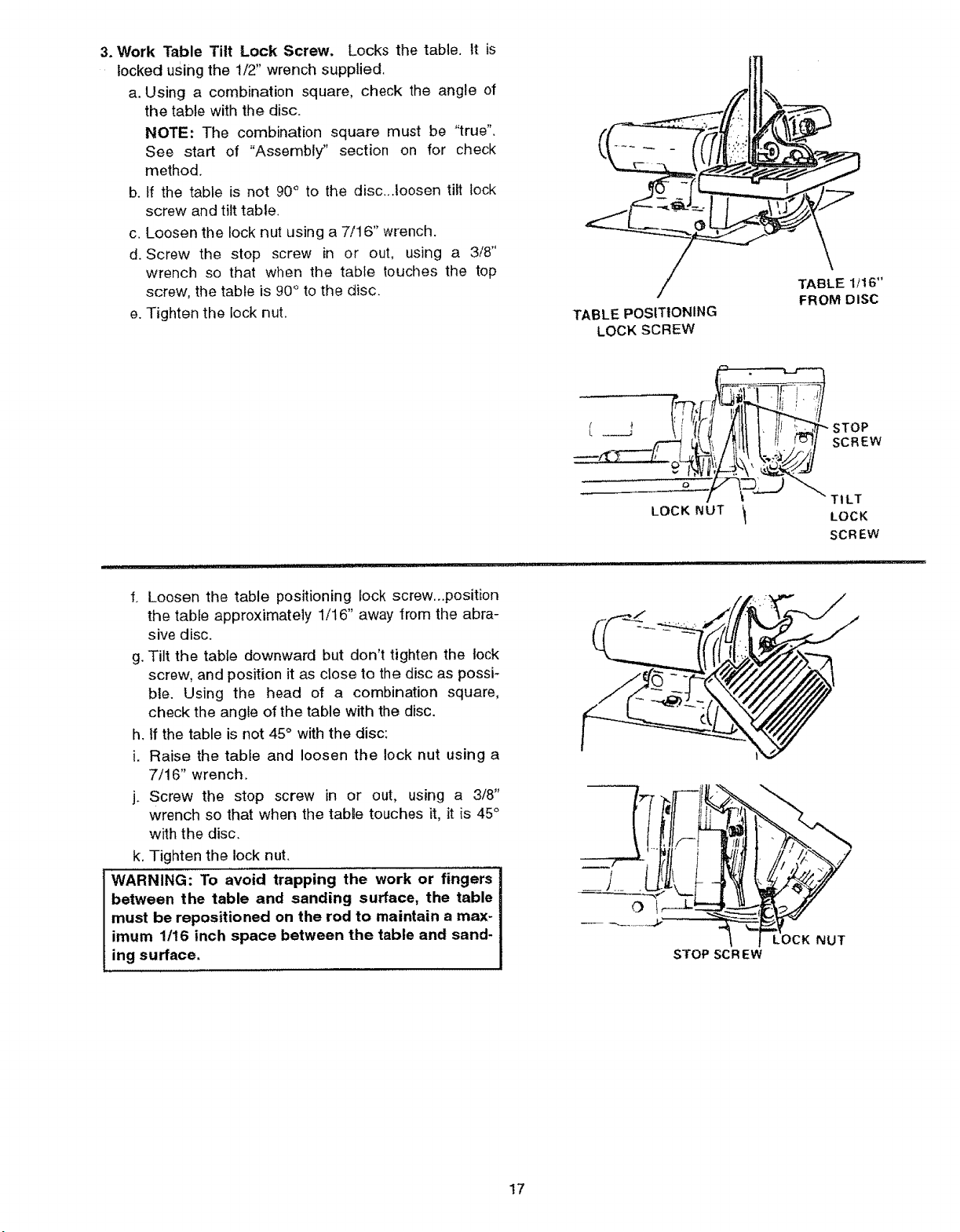
3.Work Table Tilt Lock Screw. Locks the table, it is
locked using the 1/2' wrench supplied.
a. Using a combination square, check the angle of
the table with the disc.
NOTE: The combination square must be "true".
See start of "Assembly" section on for check
method.
b. tf the table is not 90° to the disc...toosen tilt lock
screw and tilt table.
c. Loosen the lock nut using a 7/16" wrench.
d. Screw the stop screw in or out, using a 3/8"
wrench so that when the table touches the top
screw, the table is 90° to the disc.
e. Tighten the lock nut. TABLE POSITIONING
LOCK SCREW
\
TABLE 1/!6"
FROM DISC
UI_ I I'11111 IIIII![L
f. Loosen the table positioning lock screw...position
the table approximately 1/16" away from the abra-
sive disc.
g. Tilt the table downward but don't tighten the lock
screw, and position it as close to the disc as possi-
ble. Using the head of a combination square,
check the angle of the table with the disc.
h. tf the table is not 45°with the disc:
i. Raise the table and loosen the lock nut using a
7/16" wrench.
j. Screw the stop screw in or out, using a 3/8"
wrench so that when the tabte touches it, it is 45°
with the disc.
k. Tighten the lock nut.
WARNING: To avoid trapping the work or fingers
between the table and sanding surface, the table
must be repositioned on the rod to maintain a max-
imum 1/16 inch space between the table and sand-
ing surface,
L _ _i tfJ
LOCK NUT
STOP
SCREW
TILT
LOCK
SCREW
i i ii II J J _Llllll!l mill iii , ii ij _II
STOP SCR EW
17
Loading ...
Loading ...
Loading ...