Loading ...
Loading ...
Loading ...
]
SERVICE A
D AOJUSTMENTS
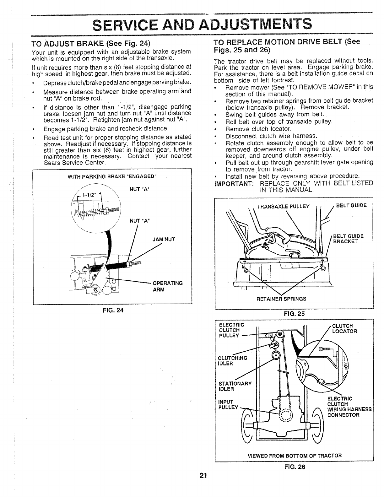
TO ADJUST BRAKE (See Fig. 24)
Your unit is equipped with an adjustable brake system
which is mounted on the right side of the transa×le.
If unit requires more than six (6) feet stopping distance at
high speed in highest gear, then brake must be adjusted;
• Depress clutch!brake pedal and engage parking brake,
o Measure distance between brake operating armand
nut "A" on brake rod.
• If distance is other than i-1/2", disengage parking
brake, loosen jam nut and turn nut "A" until distance
becomes 1-1/2". Retighten jam nut against nut "A",
o Engage parking brake and recheck distance,
o Road test unit for proper stopping distance as stated
above. Readjust if necessary. If stopping distance is
still greater than six (6) feet in highest gear, further
maintenance is necessary. Contact your nearest
Sears Service Center,
WITH PARKING BRAKE "ENGAGED"
JAM NUT
OPERATING
ARM
NUT "A"
TO REPLACE MOTION DRIVE BELT (See
Figs. 25 and 26)
The tractor drive belt may be replaced without tools,
Park the tractor on level area, Engage parking brake.
For assistance, there is a belt installation guide decal on
bottom side of left footrest.
• Remove mower (See "TO REMOVE MOWER" in this
section of this manual).
• Remove two retainer springs from belt guide bracket
(below transaxle pulley), Remove bracket,
° Swing belt guides away from belt.
° Roll belt over top of transaxie pulley.
• Remove clutch locator.
o Disconnect clutch wire harness.
o Rotate clutch assembly enough to allow belt to be
removed downwards off engine pulley, under belt
keeper, and around clutch assembly,
• Pull belt out up through gearshift lever gate opening
to remove from tractor.
• Install new belt by reversing above procedure.
IMPORTANT: REPLACE ONLY WITH BELT LISTED
IN THIS MANUAL.
_ _ IBELTGUIDE.TRANSAXLE PULLEY / BELT GUIDE
RETAINER SPRINGS
FIG. 24
FIG. 25
ELECTRIC ,CLUTCH
CLUTCH LOCATOR
PULLEY
CLUTCHING
iDLER
STATIONARY
iDLER
INPUT
ELECTRIC
CLUTCH
WIRING HARNESS
CONNECTOR
VIEWED FROM BOTTOM OF TRACTOR
FIG. 26
21
Loading ...
Loading ...
Loading ...