OWNER'S
MANUAL
MODEL NO,
917,254780
Caution:
Read and follow
all Safety Rules
and Instructions
Before Operating
This Equipment
®
12.5 HP IC
ELECTRIC START
38" MOWE ECK
6 SPEE TRANSAXLE
LAWN TRACTOR
• Assembly
• Operation
. Maintenance
. Service and Adjustment
o Repair Parts
Sears, Roebuck and Co., Chicago, _L 60684 U.S°A.
SAFETY RULES
CAUTION: ALWAYS DISCONNECTSPARK PLUGWIRE ANDPLACEWIRE WHERE IT CANNOTCONTACT SPARK
PLUG TO PREVENT ACCIDENTAL STARTING WHEN SETTING-UP, TRANSPORTING, ADJUSTING OR MAKING
REPAIRS.
IMPORTANT
&
SAFETY STANDARDS REQUIRE OPERATOR PRESENCE CONTROLS TO MINIMIZE THE RISK OF INJURY. YOUR UNIT iS EQUIPPED WITH SUCH
CONTROLS, DO NOT ATTEMPT TO DEFEAT THE FUNCTION OF THE OPERATOR PRESENCE CONTROLS UNDER ANY CIRCUMSTANCES.
TRAINING:
• Know the controls and how to stop quickly. Read this owner's
manual and instructions furnished with attachments.
• Do not allow children to operate the machine. Do not allow
adults to operate it without proper instruction.
, Do not carry passengers, Do not mow when children and
others are around.
- Do not attempt to operate your vehicle or mower when not in
the driver's seat.
• Always get on or off your vehicle from the operator's _efthand
side.
• The vehicle and attachments should be stopped and in-
spected for damage after striking a foreign object, and the
damage should be repaired before restarting and operating
the equipment.
PREPARATION:
= Always wear substantial foot-wear, Do r_ot wear loose fitting
clothing that could get caught in moving parts.
• C_ear the work area of objects (wire, rocks, etc.) which might
be picked up and thrown.
o Disengage all attachment clutches before attempting to start
the engine.
o Handle gasoline with care - it is highly flammable,
Use approved gasoline containers.
Never remove th_ fuel cap of the fuel tank or add gasoline
to a running or hot engine or an engine that has not been
allowed to cool for several minutes after running. Never
fill tank indoors. Always clean up spilled gasoline.
Open doors if the engine is run in the garage oexhaust
fumes are dangerous. De t_ot run the engine indoors.
o Do not operate the mower without the entire grass catcher,
on mowers so equipped, or the deflecto_ shield in place.
OPERATION;
o Keep your eyes and m nd on your vehicle, mower, and the
area being cut, Do not let ether interests distract you.
o Disen_jage power to attacl_ments and stop the engine before
Jeaving the operator's position.
Disengage power to mower, stop the engine, and disconnect
spark plug wire(s) from spark p_ug(s) before cleaning, making
a_nadjustment, or repair. Be careful to avoid touching hot
muffler or engine components.
o Disengage power to a_achments when transporting or not in
USe,
Take at_ possible precautions when leaving the vehicle unat-
tended. Disengage the power take-off, Jower the attach-
ments, shift into neutral, set the parking brake, stop the
engine, and remove the key.
o Do not stop or start suddenly when going uphill or downhill.
Mow up and down the face of slopes (not greater than t5°),
never across the face.
o Reduce speed on slopes and make turns gradually to prevent
tipping or loss of control. Exercise extreme caution when
changing direction on slopes.
* While going up or down slopes, place gearshift control lever
in 1st gear position to negotiate the slope without stopping.
, Never mow in wet or slippery grass, when traction is unsure,
or at a speed which could cause a skid.
, Stay alert for holes in the terrain and other hidden hazards.
Keep away from drop-offs.
. Do not drive too close to creeks, ditches, and public high-
ways.
, Exercise special care when mowing around fixed objects in
order to prevent the blades from strsking them, Never delib-
erately run vehicle or mower into or over any foreign objects,
• Never shift gears until vehicle comes to a stop,
• Never place hands or feet under the mower, in discharge
chute, or near any moving parts while vehicle or mower =s
running. Always keep clear of discharge chute.
o Use care when pulling loads or using heavy equipment.
Use only approved drawbar hitch points.
Limit loads to those you can safely control.
Do not turn sharply. Use care when backing.
Use counterweight or wheel weights when suggested in
owner's manual.
• Watch out for traffic when crossing or near roadways,
• When using any attachments, never direct discharge of
materiat toward bystanders nor allow anyone near the ve-
hicle while in operation.
o Except for adjustments, do not operate engine if air cleaner
or cover directly over carburetor air intake is remove&
Removal ef such part could createa fire hazard.
o Do not change the engine governor settings or overspeed
the engine; severe damage or injury may result°
o When using the vehicle with mower, proceed as follows:
Mow on!y in daylight or in good artificial Iighto
Shut the engine off when unclogging chute.
Check the blade mounting bolts for proper tightness at
frequent intervals.
o Disengage power to mower before backing up. Do not mow
in reverse untess absolutely necessary and then only after
careful observation of the entire area behind the mower.
MAINTENANCE AND STORAGE
o Keep the vehicle and attachments in good operating condi.
tion, and keep safety devices in place and working.
• Keep all nuts, bolts, and screws tight to be sure the equip-
ment is in safe working condition,
• Never store the equipment with gasoline in the tank inside a
building where fumes may reach an open flame or spark,
Allow the engine to cool before storing in any enclosure.
o To reduce fi re hazard, keep the engine free of grass, leaves,
or excessive grease. Do not clean product While engine is
running.
• Do not operate without a muffler, or tamper with exhaust
system. Damaged mufflers or spark arresters could create a
fire hazard, inspect periodically and replace if necessary.
• ' Under normal usage the grass catcher bag material is
subject to deterioration and wear. It should be checked
frequently for bag replacement. Replacement bags should
be checked to ensure compliance with the original
manufacturer's recommendations or specifications.
LOOK FOR THiS SYMBOL TO POINT OUT IMPORTANT SAFETY PRECAUTIONS,
iT MEANS =ATTENTIONH! BECOME ALERT!If YOUR SAFETY IS INVOLVED,
2
...... i
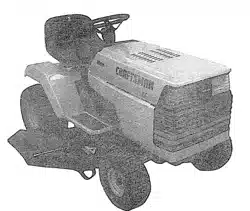
CONGRATULATIONS on your purchase of a Sears
Tractor. tt has been designed, engineered and manu-
factured to give you the best possible dependability and
performance.
Should you experience any problem you cannot easity
remedy, please contact your nearest Sears Service
Center/Department We have competent, well-trained
technicians and the proper tools to service or repair this
unit.
Please read and retain this manual. The instructions wiif
enable you to assemble and maintain your unit properly.
Always observe the "SAFETY RULES".
MODEL
NUMBER 917.254780
SERIAL
NUMBER
DATE OF PURCHASE
THE MODELAND SER1AL NUMBERS WILL BE FOUND
ON A PLATE UNDER THE SEAT.
YOU SHOULD RECORD BOTH SERIAL NUMBER AND
DATE OF PURCHASE AND KEEP IN A SAFE PLACE
FOR FUTURE REFERENCE.
MAINTENANCE AGREEMENT
A Sears Maintenance Agreement is available on this prod-
uct. Contact your nearest Sears store for details.
CUSTOMER RESPONSIBILITIES
• Read and observe the safety rules.
, Foflow a regular schedule in maintaining, caring for and
using your unit.
° Follow the instructions under "Maintenance" and
"Storage" sections of this owner's manual,
._RODUCT SPECIFICATIONS
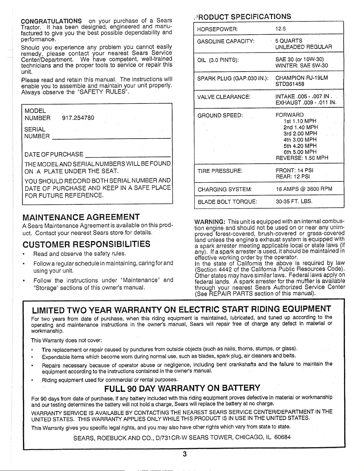
HORSEPOWER: 12.5
GASOLINE CAPACITY: 5 QUARTS
UNLEADED REGULAR
OIL (3,0 PINTS): SAE 30 (or 10W-30)
WINTER: SAE 5W_30
SPARK PLUG (GAP.030 IN.): CHAMPION RJ-19LM
STD361458
VALVE CLEARANCE: INTAKE .005-,O07'.IN.
EXHAUST .009 - .011 IN.,
GROUND SPEED: FORWARD
1st !.10 MPH
2nd 1.40 MPH
3rd 2.00 MPH
4th 3.00 MPH
5th 4.20 MPH
6th 5,00 MPH
REVERSE: 1.50 MPH
TIRE PRESSURE: FRONT: 14 PSI
REAR: 12 PSt
CHARGING SYSTEM: 16 AMPS @ 3600 RPM
BLADE BOLT TORQUE: 30-35 FT. LBS.
WARNING; This unit is equipped with an internal combus-
tion engine and should not be used on or near any unim-
proved forest-covered, brush-covered or grass-covered
land unless the engine's exhaust system is equipped with
a spark arrester meeting applicable local or state laws (if
any). If a spark attester _sused, it should be maintained in
effective working order by the operator.
in the state of California the above is required by law
(Section 4442 of the California Public Resources Code).
Other states may have similar Iaws. Federal laws apply on
federal lands. A spark attester for the muffler is available
through your nearest Sears Authorized Service Center
(See REPAIR PARTS section of this manual).
LIMITED TWO YEAR WARRANT'/' ON ELECTRIC START RIDING EQUIPMENT
For two years from date of purchase, when this riding equipment is maintained, lubricated, and tuned up according to the
operating and maintenance instructions in the owner's manual, Sears will repair free of charge any defect in material or
workmanship.
This Warranty does not cover:
• Tire replacement or repair caused by punctures from outside objects (such as nails, thorns, stumps, or glass).
, Expendable items which become worn during normal use, such as blades, spark plug, air cIeaners and belts.
• Repairs necessary because of operator abuse or negligence, including bent crankshafts and the failure to maintain the
equipment according to the instructions contained in the owner's manual.
• Riding equipment used for commercial or rental purposes.
FULL 90 DAY WARRANTY ON BATTERY
For 90 days from date of purchase, if any battery Included with this riding equipment proves defective in material or workmanship
and our testing determines the battery will not hold a charge, Sears wilt replace the battery at no charge.
WARRANTY SERVICE IS AVAILABLE BY CONTACTING THE NEAREST SEARS SERVICE CENTER/DEPARTMENT IN THE
UNITED STATES. THIS WARRANTY APPLIES ONLY WHILE THIS PRODUCT IS tN USE iN THE UNITED STATES.
This Warranty gives you specific legal rights, and you may also have other rights which vary from state to state.
SEARS, ROEBUCK AND CO., Di731CR-W SEARS TOWER, CHICAGO, IL 60684
TABLE
SAFETY RULES ............................................................ 2
PRODUCT SPECiFiCATIONS ....................................... 3
CUSTOMER RESPONSIBILITIES ................................. 3
WARRANTY ................................................................... 3
TABLE OF CONTENTS ................................................. 4
INDEX ............................................................................. 4
TRACTOR ACCESSORIES ........................................... 5
ASSEMBLY ................................................................ 7-9
OF CONTENTS
OPERATION ........................................................... 10-13
MAINTENANCE ...................................................... 14-17
SERVICE AND ADJUSTMENTS ............................ 18-24
STORAGE .................................................................... 25
TROUBLESHOOTING ............................................ 26-27
REPAIR PARTS - TRACTOR ................................. 30-43
REPAIR PARTS =ENGINE ..................................... 44-48
PARTS ORDERING/SERVICE ................... BACK PAGE
INDEX
A
Accessories ............................................ 5
Adjustments:
Brake ........................................... 21
Carburetor ................................... 24
Mower
Front-To-Back ........................ 19
Side-To-Side .......................... 18
Throttle Control Cable ................. 24
Air Filter, Engine ................. ................ 16
Air Screen, Engine ............................. 17
Assembly ........................................... 7-9
B
Battery:
Charging ........................................ 8
Cleaning ...................................... 16
Installation ..................................... 9
Levels ....................................... 8,t6
Preparation .................................... 8
Starting with Weak Battery .......... 22
Storage ........................................ 25
Terminals .................................... 16
Belt:
Motion Drive
Removal/Replacement ........... 21
Mower Blade Drive
Removal/Replacement ........... 20
Blade:
Sharpening .................................. 15
Replacement ............................... 15
Brake Adjustment ............................... 21
C
Carburetor Adjustment ....................... 24
Controls, Tractor ................................. 10
Cutting Height, Mower ........................ 11
E
Electrical:
interlocks and Relays .................. 23
Schematic ................................... 29
Wiring Diagram ............................ 30
Engine:
Air Filter ....................................... 16
Air Filter Foam Pre-Cleaner ....... 116
Air Screen ................................... 17
Cooling Fins, Engine ................... t7
Oil Change .................................. 16
Oil Level ................................. !2,16
Oil Type ....................................... 16
Preparation .................................. 12
Repair Parts ........................... 44-48
Starting ........................................ t 3
Storage ........................................ 25
F
Filter:
Air Filter ....................................... 16
Air Filter Foam Pre-Cleaner ........ 16
Fu el ............................................. 17
Fuel:
Type ............................................ 12
Storage ........................................ 25
Fuse .................................................... 23
H
Hood Removal/Installation .................. 23
L
Leveling Mower Deck .................... 18-!9
Lubrication:
Chart ............................................ 14
M
Maintenance .................................. 14-17
Air Filter ....................................... 16
Air Filter Foam Pre..Cteaner ........ t6
Air Screen, Engine ...................... 17
Battery ......................................... 16
Blade ........................................... 15
Cooling Fins, Engine .................... 17
Engine Oil .................................... 16
Fuel Fitter .................................... 17
Lubrication Chart ......................... 14
Schedule ..................................... 14
Spark Plugs ................................. !7
Tire Care ............................. 8,15,22
Mower:
Adjustment, From-to-Back ........... 19
Adjustment, Side-to-Side ............. 18
Blade Sharpening ........................ 15
Blade Replacement ..................... 15
Cutting Height .............................. 11
Installation ................................... 18
Operation ..................................... 12
Removal ...................................... 18
Mowing Tips ....................................... 13
Muffler ................................................. 17
Spark Arrester .......................... 3,34
O
Oil:
Cold Weather Conditions ....... 12,16
Engine ............. ............................ 16
Storage ......... _.............................. 25
Operation ....................................... 10-13
Operating Mower ................................ 12
Options:
Accessories ................................... 5
Spark Attester .......................... 3,34
4
P
ParkingBrake ................................ 10-11
Parts Bag.............................................. 6
Parts, RepfacementjRepair ............30-48
Product Specifications ...........................3
R
Repair Parts .................................. 30-48
S
Safety Rules ......................................... 2
Seat ......................................................8
Set€ice and Adjustments .............. t8-24
Carburetor ................................... 24
Fuse ............................................ 23
Hood Removal/Installation .......... 23
Motion Drive Belt
Removal/Replacemant ........... 21
Mower Blade Drive Belt
Removal/Replacement ........... 20
Mower Adjustment
Front- to-Back ........................ 19
Side-to-Side ............................ 18
Mower Removal .......................... 18
Tire Care ............................. 8,! 5,22
Slope Guide Sheet ............................. 51
Spark Plugs ........................................ 17
Specifications ....................................... 3
Starting the Engine ........................ 12-! 3
Steering Wheel ................................ 7,22
Stopping the Tractor ........................... 1t
Storage ............................................... 25
T
Throttle Centre! Cable
Adjustment .................. ................ 24
Tires................................................... 8,15,22
Trouble Shooting Chart .................. 26-27
Transaxle:
Repair Parts .......... ................. 42-43
W
Warranty ............................................... 3
Wiring Diagram .................................. 30
Wiring Schematic ............................... 29
.... i
..... i
ACCESSO ES AND ATTACH
NTS
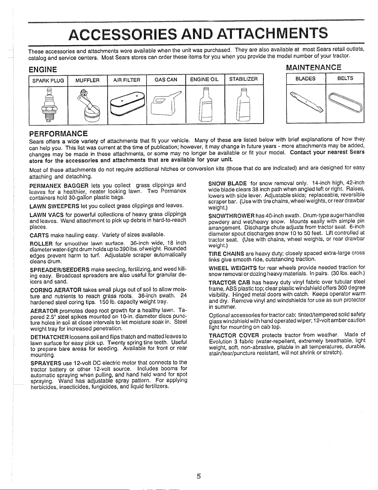
These accessories and attachments were available when the unit was purchased. They are also available at most Sears retail outlets,
catalog and service centers. Most Sears stores can order these items for you when you provide the model number of your tractor.
ENGINE
SPARK PLUG
AIR FILTER GAS CAN
MUFFLER
I
ENGINE OIL STABILIZER
MAINTENANCE
BELTS
BLADES
PERFORMANCE
Sears offers a wide variety of attachments that fit your vehicle. Many of these are listed below with brief explanations of how they
can help you. This list was current at the time of publication; however, it may change in future years * more attachments may be added,
changes may be made in these attachments, or some may no longer be available or fit your model. Contact your nearest Sears
store for the accessories and attachments that are available for your unit.
Most of these attachments do not require additional hitches or conversion kits (those that do are indicated) and are designed for easy
attaching and detaching,
PERMANEX BAGGER lets you collect grass clippings and
leaves for a healthier, nearer looking lawn. Two Permanex
containers hold 30-gallon plastic bags.
LAWN SWEEPERS let you collect grass clippings and leaves.
LAWN VACS for powerful collections of heavy grass clippings
and leaves. Wand attachment to pick up debris in hard-to-reach
places,
CARTS make hauling easy. Variety of sizes available.
ROLLER for smoother lawn surface. 36-inch wide, 18 inch
diameterwater4ight drum holds upto3901bs, of weight. Rounded
edges prevent harm to turf. Adjustable scraper automatically
cleans drum,
SPREADER!SEEDERS make seeding, fertilizing, and weed kill-
ing easy. Broadcast spreaders are also useful for granular de-
icers and sand.
CORING AERATOR takes small plugs out of soil to allow mois-
ture and nutrients to reach grass roots. 36-inch swath. 24
hardened steel coring tips. 150 lb. capacity weight tray,
AERATOR promotes deep root growth for a healthy lawn. Ta-
pered 2.5" steel spikes mounted on 10-in. diameter discs punc-
ture holes in soil at close intervals to let moisture soak in. Steel
weight tray for increased penetration.
DETHATCHER loosens soil and flips thatch and matted leaves to
lawn surface for easy pick up. Twenty spring tine teeth. Useful
to prepare bare areas for seeding. Available for front or rear
mounting.
SPRAYERS use 12-volt DC electric motor that connects to the
tractor battery or other 12-volt source. Includes booms for
automatic spraying when pulling, and hand held wand for spot
spraying. Wand has adjustable spray pattern. For applying
herbicides, insecticides, fungicides, and liquid fertilizers.
SNOW BLADE for snow removal only. 14-inch high, 42-inch
wide blade clears 38 inch path when angled left or right. Raises,
lowers with side lever, Adjustable skids; replaceable, reversibfe
scraper bar. (Use with tire chains, wheel weights, or rear drawbar
weight.)
SNOWTHROWER has 40-inch swath. Drum-type auger handles
powdery and wet/heavy snow. Mounts easily with simple pin
arrangement. Discharge chute adjusts from tractor seat. 6-inch
diameter spout discharges snow 10 to 50 feet. Lift controlled at
tractor seat. (Use with chains, wheel weights, or rear drawbar
weight.)
TIRE CHAINS are heavy duty; closely spaced extra-large cross
links give smooth ride, outstanding traction.
WHEEL WEIGHTS for rear wheels provide needed traction for
snow removal or dozing heavy materials. In pairs. (30 tbs. each.)
TRACTOR CAB has heavy duty vinyl fabric over tubular steel
frame, ABS plastic top; clear plastic windshield offers 360 degree
visibility. Hinged metal doors with catch. Keeps operator warm
and dry, Remove vinyl and windshields for use as sun protector
in summer.
Optional accessories for tractor cab: tinted/tempered solid safety
glass windshield with hand operated wiper; 12-volt amber caution
light for mounting on cab top.
TRACTOR COVER protects tractor from weather. Made of
Evolution 3 fabric (water-repellent, extremely breathable, light
weight, soft, non-abrasive, pliable in all temperatures, durabte,
stain/tear/puncture resistant, will not shrink or stretch).
5
-4
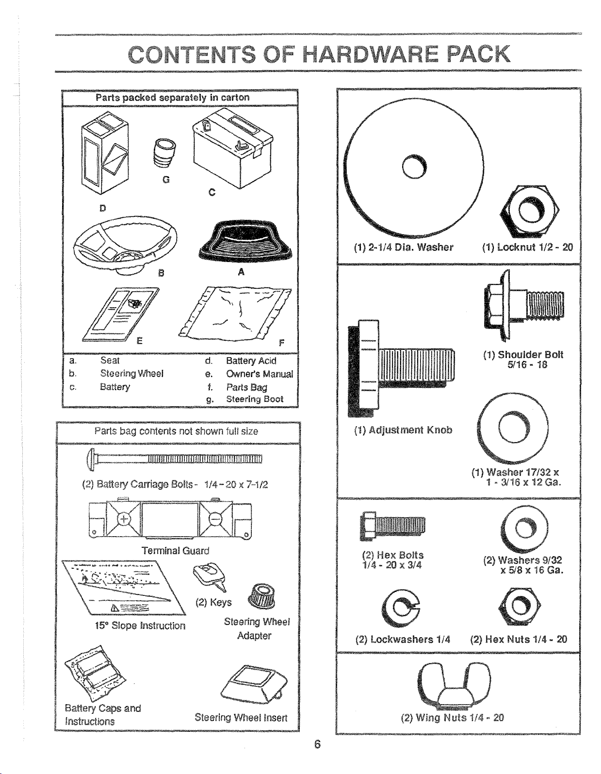
Parts packed separa_eiy in carton
¢
D
A
a, Seat d. Battery Acid
b. Steering Wheel e. Owner's Manual
c. Batte_ f. Pans Bag
g, Steetln 9 Boot
Parts bag contents not shown rut size
(2) Battery Carriage Bols- t/4-20 × 7-t/2
Terminaa Guard
15° SLope Instruction
Battery Caps and
instructions
(2) Keys
Steering Wheel
Adapter
Steering Wheeg insert
ARDWARE
©
(1) 2-I/4 Dia, Washer (1) Locknut 112 - 20
(1) Shoulder Bolt
5116- t8
(I) Adjustment Knob
6
(1) Washer 17/32 x
1 - 3/16 × 12 Ga.
(2) He× Bolts
1/4 = 20 × 3/4
(2) Washers 9/32
x 5/8 x !6 Ga.
(b
(2) Lockwashers 1/4
@
(2) Hex Nuts 1/4 - 20
QP
(2) Wing Nu_s ii4 = 20
ASSE LY
TOOLS REQUIRED FOR ASSEMBLY
A socket wrench set wilI make assembly easier. Standard 1/2- 20 HEXNUT
wrench sizes are listed.
(1) 5/16" wrench
(2) 7/16" wrenches
(1) 1/2" wrench
(1) 9/16" wrench
(1) 3/4" wrench
Tire pressure gauge
Screwdriver
Utility knife
When right and left hand is mentioned in this manuat, it
means when you are in the operating position (seated be-
hind the steering wheel).
TO REMOVE UNIT FROM CARTON
UNPACK CARTON
• Remove all loose parts from carton (See page 6).
• Cut, from top to bottom, all four corners of carton and
lay panels flat.
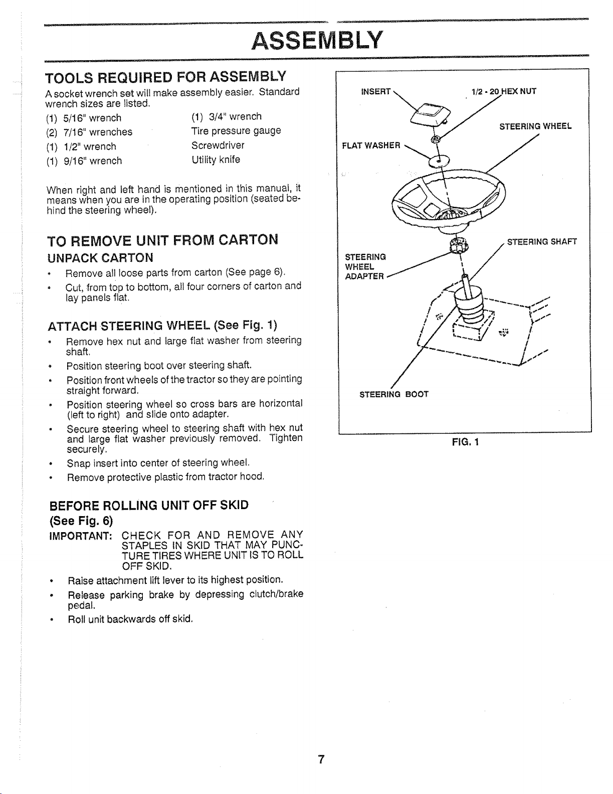
ATTACH STEERING WHEEL (See Fig. !)
• Remove hex nut and large fiat washer from steering
shaft.
• Position steering boot over steering shaft.
, Position front wheels of the tractor so they are pointing
straight forward.
o Position steering wheel so cross bars are horizontal
(left to right) and slide onto adapter.
, Secure steering wheel to steering shaft with hex nut
and large flat washer previously removed. Tighten
securely.
• Snap insert into center of steering wheel.
• Remove protective pIastic from tractor hood.
FLAT WASHER
STEERSNG WHEEL
STEERING BOOT
FIG. 1
BEFORE ROLLING UNIT OFF SKID
(See Fig. 6)
IMPORTANT: CHECK FOR AND REMOVE ANY
STAPLES fN SKID THAT MAY PUNC-
TURE TIRES WHERE UNiT IS TO ROLL
OFF SKID.
• Raise attachment lift lever to its highest position.
, Release parking brake by depressing clutch/brake
pedal.
• Roll unit backwards off skid.
7
ASSE
HOW TO SET UP YOUR TRACTOR
PREPARE BATTERY (See Fig. 2)
CAUTION: Wear eye and face shield.
Wash hands or clothing immediately if
accidentally in contact with battery acid,
Do not smoke. Fumes from charged
battery acid are explosive.
Read the instructions included with the
batteryvent caps. Alwayswear gtoves,
clothing and goggles to protect your
hands, skin and eyes.
LY
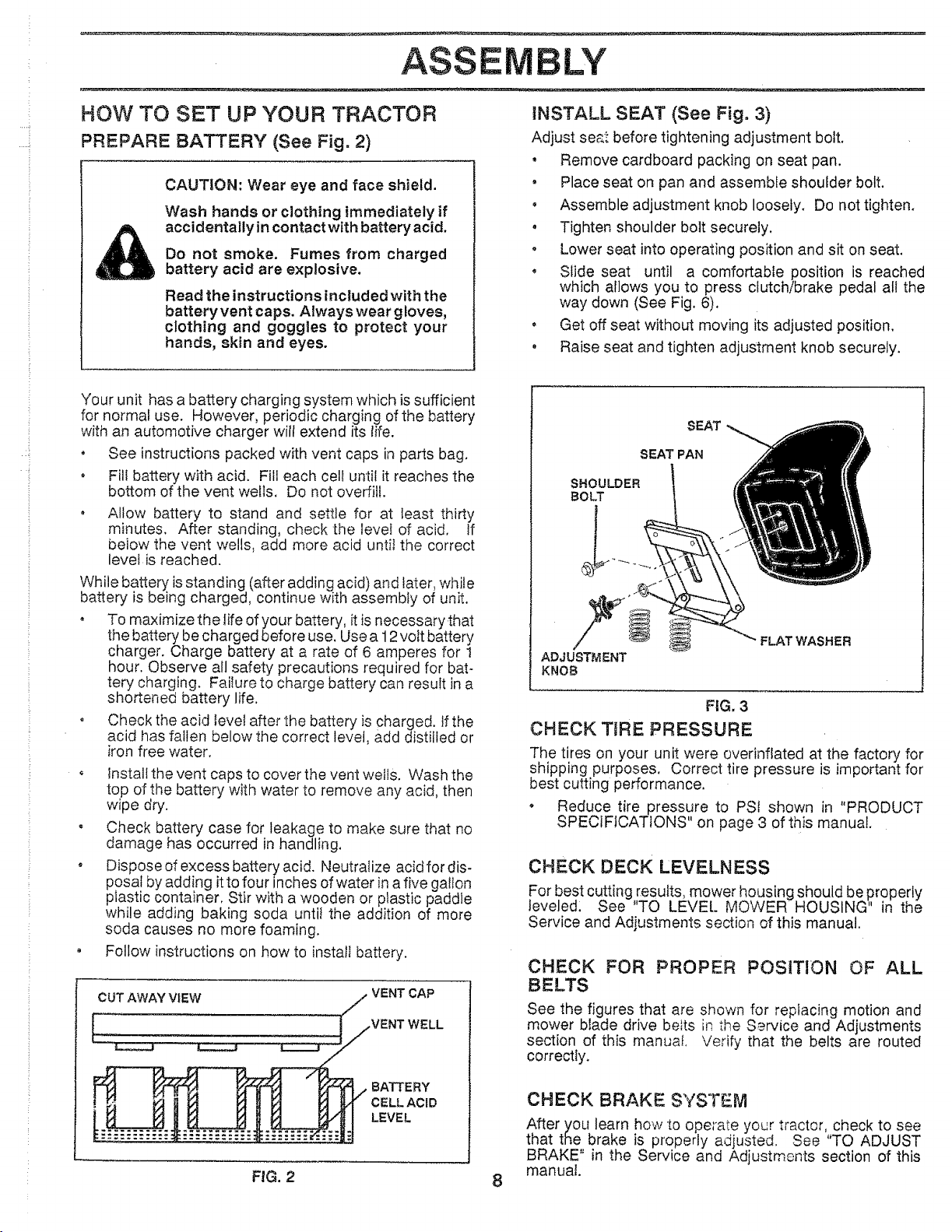
INSTALL SEAT (See Fig. 3)
Adjust se£_ before tightening adjustment bolt,
• Remove cardboard packing on seat pan.
, Place seat on pan and assemble shoulder bolt,
• Assemble adjustment knob loosely, Do not tighten,
• Tighten shoulder bolt securely.
o Lower seat into operating position and sit on seat.
• Slide seat until a comfortable position is reached
which allows you to press clutch/brake pedal all the
way down (See Fig. 6).
, Get off seat without moving its adjusted position.
• Raise seat and tighten adjustment knob securely,
Your unit has a battery charging system which is sufficient
: for normal use. However, periodic charging ofthe battery
: with an automotive charger will extend its life.
, See instructions packed with vent caps in parts bag.
o Fill battery with acid. Fill each cell until it reaches the
bottom of the vent wells. Do not overfill.
Allow battery to stand and settle for at least thirty
minutes. After standing, check the level of acid. If
below the vent wells, add more acid until the correct
level is reached.
While battery is standing (after adding acid) and later, while
battery is being charged, continue with assembly of unit.
, To maximize the life of your battery, it is necessary that
the battery be charged before use. Use a 12 volt battery
charger. Charge battery at a rate of 6 amperes for !
hour. Observe all safety precautions required for bat-
tery charging. FaiIure to charge battery can result in a
shortened battery life.
o Check the acid level after the battery is charged, tf the
acid has fallen below the correct level, add distilled or
iron free water.
o Install the vent caps to cover the vent wells. Wash the
top of the battery with water to remove any acid, then
wipe dry.
, Check battery case for leakage to make sure that no
damage has occurred in handling.
• Dispose of excess battery acid. Neutralize acidfordis-
posaf by adding itto four inches of water in a five gallon
plastic container. Stir with a wooden or plastic paddle
while adding baking soda until the addition of more
soda causes no more foaming.
• Follow instructions on how to install battery.
CUT AWAY VIEW
VENT CAP
BATTERY
CELL ACID
LEVEL
SEAT
SEAT PAN
SHOULDER
BOLT
ADJUSTMENT
KNOB
FLAT WASHER
FIG, 3
CHECK T_RE PRESSURE
The tires on your unit were overinflated at the factory for
shipping purposes. Correct tire pressure is important for
best cutting performance.
, Reduce tire pressure to PSt shown in "PRODUCT
SPECIFICATIONS" on page 3 ofth s manual.
CHECK DECK LEVELNESS
For best cutting r:esults, mower housing should be properly
leveled: See TO LEVEL MOWER HOUSING" in the
Service and Adjustments section of this manual.
CHECK FOR PROPER POSITION OF ALL
BELTS
See the figures that are shown for repiacing motion and
mower blade drive belts in the S_rvice and Adjustments
section of this manuaf. Verify that the belts are routed
correctly.
CHECK BRAKESYSTEM
After you learn how to operate your tractor, check to see
that the brake is properly adjusted. See "TO ADJUST
BRAKE" in the Service and Adjustments section of this
manual.
FIG. 2 8
...... !,
!
..... i
ASS
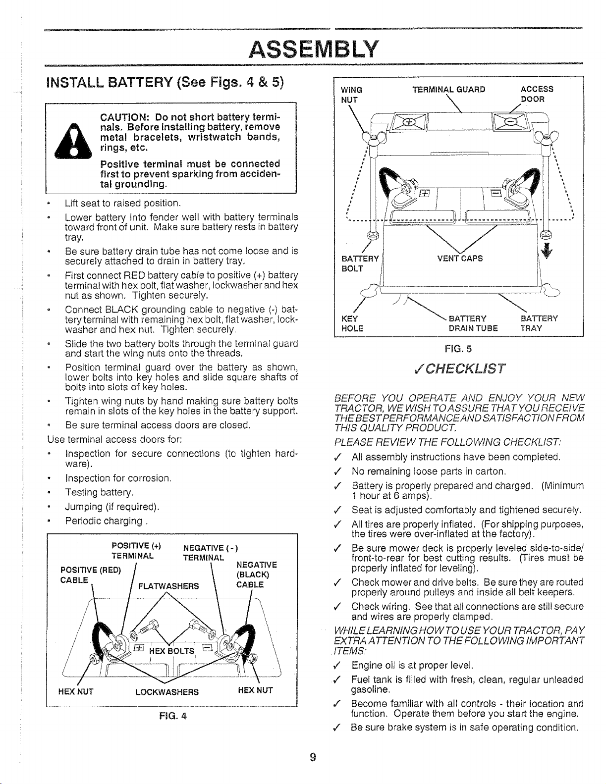
INSTALL BATTERY (See Figs. 4 & 5)
CAUTION: Do not short battery termi-
nals. Before installing battery, remove
metal bracelets, wristwatch bands,
rings, etc.
Positive terminal must be connected
first to prevent sparking from acciden-
tal grounding.
• Lift seat to raised position.
• Lower battery into fender well with battery terminals
toward front of unit. Make sure battery rests in battery
tray.
, Be sure battery drain tube has not come loose and is
securely attached to drain in battery tray.
• First connect RED battery cable to positive (+) battery
terminal with hex bolt, flat washer, Iockwasher and hex
nut as shown. Tighten securely.
o Connect BLACK grounding cable to negative (-) bat-
tery terminal with remaining hex bolt, flat washer, lock-
washer and hex nut. Tighten securely,
° Slide the two battery bolts through the terminal guard
and start the wing nuts onto the threads.
• Position terminal guard over the battery as shown,
lower bolts into key holes and slide square shafts of
bolts into slots of key holes.
• Tighten wing nuts by hand making sure battery bolts
remain in slots of the key holes in the battery support.
• Be sure terminal access doors are closed.
Use terminal access doors for:
• inspection for secure connections (to tighten hard-
ware).
o Inspection for corrosion.
• Testing battery.
• Jumping (if required).
, Periodic charging.
POSITIVE (+) NEGATIVE (-)
TERMINAL TERMINAL
POSITIVE (R ED) NEGATIVE
CABLE (BLACK)
FLATWASHERS CABLE
\
HEX NUT
LOCKWASHERS
HEXNUT
FIG. 4
LY
WING
NUT
TERMINAL GUARD ACCESS
DOOR
BATTERY VENT CAPS i_"_
;L
BOLT , _!i_._
KEY BATTERY BATTERY
HOLE BRAIN TUBE TRAY
FIG, 5
7CHECKMST
BEFORE YOU OPERATE AND ENJOY YOUR NEW
TRACTOR, WE WISH TO ASSURE THAT YOU RECEIVE
THE BY-"STPERFORMANCEAND SA TISFA CTtON FROM
THIS QUALITY PRODUCT.
PLEASE REVIEW THE FOLLOWING CHECKLIST."
¢' All assembly instructions have been completed,
v" No remaining loose parts in carton,
,/ Battery is properly prepared and charged. (Minimum
1 hour at 6 amps).
V" Seat is adjusted comfortably and tightened securely.
,/ All tires are properly inflated. (For shipping purposes,
the tires were over-inflated at the factory).
¢" Be sure mower deck is properly leveled side-to-side/
front-to-rear for best cutting results. (Tires must be
properly inflated for leveling),
,/ Check mower and drive belts, Be sure they are routed
properly around pulleys and inside all belt keepers.
¢" Check wiring, See that aIf connections are still secure
and wires are properly clamped.
WHILE LEARNING HOWTO USE YOUR TRACTOR, PAY
EXTRA ATTENTION TO THE FOLLO WING IMPORTANT
ITEMS:
v" Engine oil is at proper level.
,/ Fuel tank is filled with fresh, clean, regular unleaded
gasoline.
v" Become familiar with all controls - their location and
function, Operate them before you start the engine.
,/ Be sure brake system is in safe operating condition.
9
OPERATION
KNOW YOUR TRACTOR
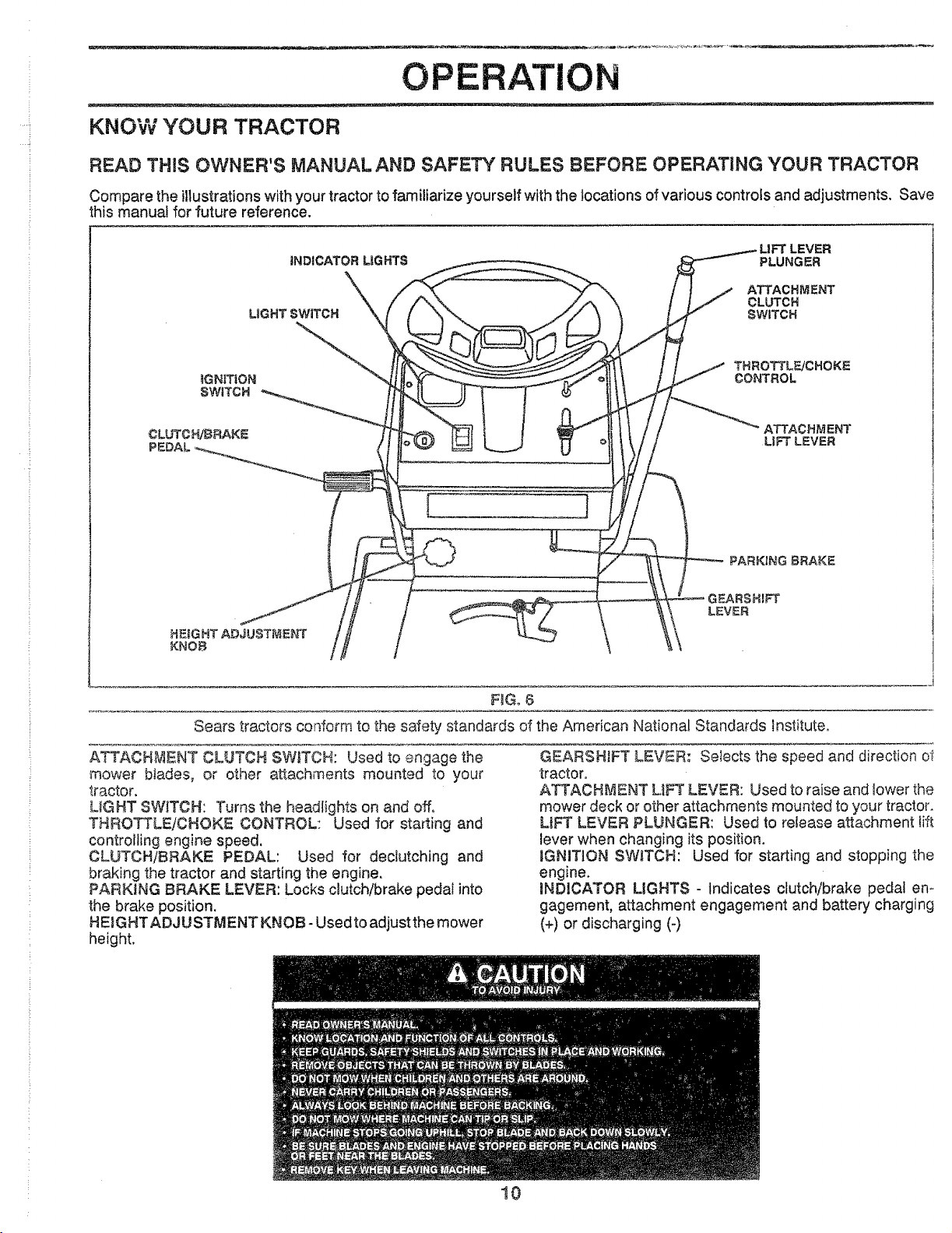
READ THIS OWNER'S MANUALAND SAFETY RULES BEFORE OPERATING YOUR TRACTOR
Compare the illustrations with your tractor to familiarize yourself with the locations of various controls and adjustments, Save
this manua! for future reference,
PLEVER
_NDICATOR LIGHTS PLUNGER
LIGHT SWITCH
ATTACHMENT
CLUTCH
SWITCH
THROTTL_CHOKE
CONTROL
[ 1
F_Go6
Sears tractors conform to the safety standards of the American National Standards institute.
ATTACHMENT CLUTCH SWtTCN: Used to engage the
mower blades, or other attachments mounted to your
tractor.
L_GHT SWITCH: Turns the headlights on and off.
THROTTLE/CHOKE CONTROL: Used for starting and
controlling engine speed.
CLUTCH/BRAKE PEDAL: Used for declutching and
braking the tractor and starting the engine.
PARKING BRAKE LEVER: Locks clutch/brake pedal into
the brake position.
HEIGHTADJUSTMENT KNOB- Used to adjust the mower
height.
10
GEARSHIFT LEVER: Selects the speed and direction oI
tractor,
ATTACHMENT LiFT LEVER: Used to raise and lower the
mower deck or other attachments mounted to your tractor,
LiFT LEVER PLUNGER: Used to release attachment lift
lever when changing its position.
aGNITJON SWITCH: Used for starting and stopping the
engine.
iNDICATOR LIGHTS - Indicates clutch/brake pedal en-
gagement, attachment engagement and battery charging
(+) or discharging (-)
..... i
..... i
OPERATION
The operation of any tractor can result in foreign objects thrown into the eyes, which can
result in severe eye damage. Always wear safety glasses or eye shields while operating
your tractor or performing any adjustments or repairs, We recommend wide vision safety
mask for over the spectacles or standard safety glasses, available at Sears Retail or
Catalog stores.
HOW TO USE YOUR TRACTOR
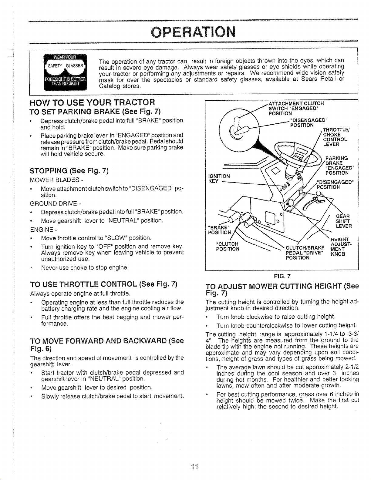
TO SET PARKING BRAKE (See Fig, 7)
• Depress clutch/brake pedal into full "BRAKE" position
and hold.
, Place parking brake lever in "ENGAGED" position and
release pressurefrom clutch/brake pedal. Pedal should
remain in "BRAKE" position. Make sure parking brake
will hold vehicle secure.
STOPPING (See Fig. 7)
MOWER BLADES -
• Move attachment clutch switch to "D!SENGAGED" po-
sition.
GROUND DRIVE -
, Depress clutch/brake pedal into ful! "BRAKE" position.
• Move gearshift lever to "NEUTRAL" position.
ENGINE -
• Move throttle control to "SLOW" position.
• Turn ignition key to "OFF" position and remove key.
Always remove key when leaving vehicle to prevent
unauthorized use.
. Never use choke to stop engine.
TO USE THROTTLE CONTROL (See Fig. 7)
Always operate engine at full throttle.
- Operating engine at less than full throttle reduces the
battery charging rate and the engine cooling air flow.
• Full throttle offers the best bagging and mower per-
formance.
TO MOVE FORWARD AND BACKWARD (See
Fig. 6)
The direction and speed of movement is controlled by the
gearshi!! lever.
, Start tractor with clutch/brake pedal depressed and
gearshift lever in "NEUTRAL" position.
o Move gearshift lever to desired position.
• Slowly release clutch/brake pedal to start movement.
IGNITION
KEY
CLUTCH
SWITCH "ENGAGED"
POSITION
POSITION
THROTTLE/
)KE
CONTROL
LEVER
"BRAKE"
POSITION
GEAR
SHIFT
LEVER
HEIGHT
"CLUTCH" ADJUST-
POSITION M ENT
PEDAL "DRIVE" KNOB
POSITION
FIG. 7
TO ADJUST MOWER CUTTING HEIGHT (See
Fig. 7)
The cutting height is controlled by turning the height ad-
justment knob in desired direction.
, Turn knob clockwise to raise cutting height.
o Turn knob counterclockwise to lower cutting height.
The cutting height range is approximately 1-1/4to 3-3/
4". The heights are measured from the ground to the
blade tip with the engine not running. These heights are
approximate and may vary depending upon soil condi-
tions, height of grass and types of grass being mowed.
o The average lawn should be cut approximately 2-1/2
inches during the cool season and over 3 inches
during hot months. For healthier and better looking
lawns, mow often and after moderate growth.
o For best cutting performance, grass over 6 inches in
height should be mowed twice. Make the first cut
relatively high; the second to desired height.
OP ATIO
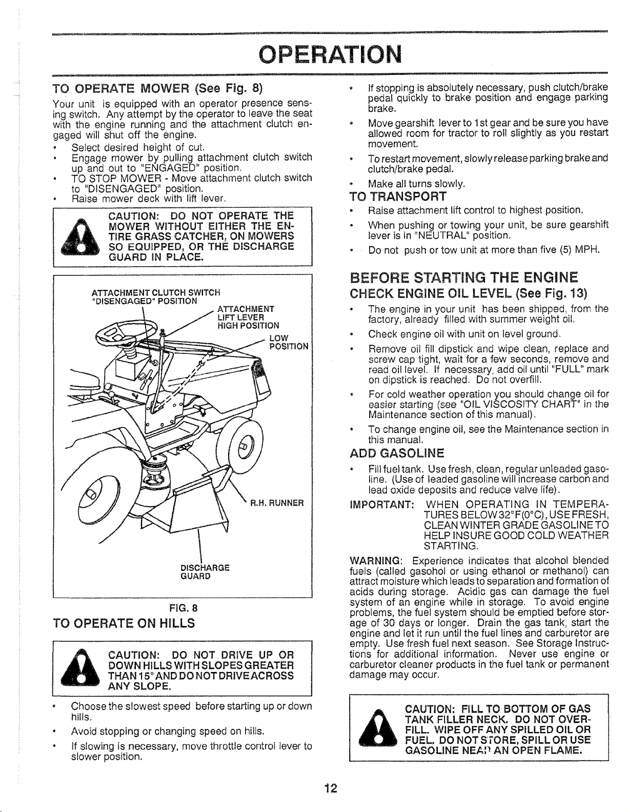
TO OPERATE MOWER (See Fig. 8)
Your unit is equipped with an operator presence sens-
ing switch. Any attempt by the operator to leave the seat
with the engine running and the attachment dutch en-
gaged will shut off the engine.
. Select desired height of cut,
. Engage mower by puliJng attachment dutch switch
up and out to "ENGAGED" position,
. TO STOP MOWER - Move attachment clutch switch
to "DISENGAGED" position.
, Raise mower deck with lift lever.
CAUTION: DO NOT OPERATE THE
MOWER WITHOUT EITHER THE EN-
TIRE GRASS CATCHER, ON MOWERS
SO EQUIPPED, OR THE DISCHARGE
GUARD IN PLACE.
, If stopping is absolutely necessary, push clutch/brake
pedal quickly to brake position and engage parking
brake.
• Move gearshift lever to 1st gear and be sure you have
allowed room for tractor to roll slightly as you restart
movement.
. To restart movement, slowly release parking brake and
clutch/brake pedal.
* Make all turns slowly.
TO TRANSPORT
. Raise attachment lift control to highest position.
° When pushing or towing your unit, be sure gearshift
lever is in "NEUTRAL" position.
. _ Do not push or tow unit at more than five (5) MPH.
ATrAOHi_ENT CLUTCH SWITCH
"DISENGAGED" POSITION
ATTACHMENT
L_FT LEVER
HIGH POSITION
R.H, RUNNER
DISCHARGE
GUARD
FIG. 8
TO OPERATE ON HILLS
CAUTION: DO NOT DRIVE UP OR
DOWN HILLS WITH SLOPES GREATER
THAN 15° AND DO NOT ORtVEACROSS
ANY SLOPE.
BEFORE STARTING THE ENGINE
CHECK ENGINE O_L LEVEL (See Fig. 13)
° The engine in your unit has been shipped, from the
factory, aiready filled with summer weight oil,
. Check engine oil with unit on level ground,
• Remove oil fill dipstick and wipe clean, replace and
screw cap tight, wait for a few seconds, remove and
read oil level If necessary, add oil until "FULL" mark
on dipstick is reached. Do not overfill.
, For cold weather operation you should change oil for
easier starting (see "OIL VISCOSITY CHART" in the
Maintenance section of this manual).
, To change engine oil, see the Maintenance section in
this manual.
ADD GASOLINE
o Fill fuettank. Use fresh, clean, regular unleaded gaso-
line. (Use of leaded gasoline wilt increase carbon and
lead oxide deposits and reduce valve life).
IMPORTANT: WHEN OPERATING IN TEMPERA-
TURES BELOW32°F(0°C), USE FRESH,
CLEAN WINTER GRADE GASOLINE TO
HELP INSURE GOOD COLD WEATHER
STARTING.
WARNING: Experience indicates that alcohol blended
fuels (called gasohol or using ethanol or methanol) can
attract moisture which leads to separation and formation of
acids during storage. Acidic gas can damage the fuel
system of an engine while in storage, To avoid engine
problems, the fuel system should be emptied before stor-
age of 30 days or longer. Drain the gas tank, start the
engine and let it run until the fuel lines and carburetor are
empty. Use fresh fuel next season. See Storage Instruc-
tions for additional information. Never use engine or
carburetor cleaner products in the fuel tank or permanent
damage may occur.
o
Choose the slowest speed before starting up or down
hills.
Avoid stopping or changing speed on hills.
if siowing is necessary, move throttle control lever to
slower position.
CAUTION: FILL TO BOTTOM OF GAS
TANK FILLER NECK. DO NOT OVER-
FILL. WIPE OFF ANY SPILLED OIL OR
FUEL, DO NOT STORE, SPILL OR USE
GASOLINE NEAP AN OPEN FLAME.
12
.... !
..... i
OPERAT!
TO START ENGINE (See Fig. 7)
When starting engine for the first time or if engine has
run out of fuel, it will take extra cranking time to move
fuel from the tank to the engine,
, Depress the clutch/brake pedal and set the parking
brake,
. Place gearshift lever in "NEUTRAL" position.
* Move attachment ciutch to "DISENGAGED" position,
, Move throttle control lever to "CHOKE" position for
cold engine start, For warm engine start, move
throttle control to "FAST" position.
. Turn ignition key clockwise to "START" position and
release key as soon as engine starts. Do not run
starter continuously for more than fifteen seconds
per minute, If engine does not start after several
attempts, move throttle control to "FAST" position,
wait a few minutes and try again,
, When engine starts, move throttte control to desired
position,
, AiIow engine to warm up for a few minutes before
engaging drive or attachment clutch,
NOTE: If at a high altitude (above 3000 feet) or in cold
temperatures (below 32 ° F), the carburetor fuel mixture
may need to be adjusted for best engine performance,
See "TO ADJUST CARBURETOR" in the Service and
Adjustments section of this manual.
MOWING TIPS
, Tire chains cannot be used when the mower hous-
ing is attached to unit,
• Mower should be properly leveled for best mowing
performance, See "TO LEVEL MOWER HOUSING"
in the Service and Adjustments section of this
manual,
• Use the runner on the right hand side of mower as
a guide, The blade cuts approximately an inch
outside the runner (See Fig. 8).
• The left hand side of mower should be used for trim-
ming.
O
Drive so that clippings are discharged onto the area
that has been cut. Have the cut area to the right of
the machine. This will result in a more even distri-
bution of clippings and more uniform cutting.
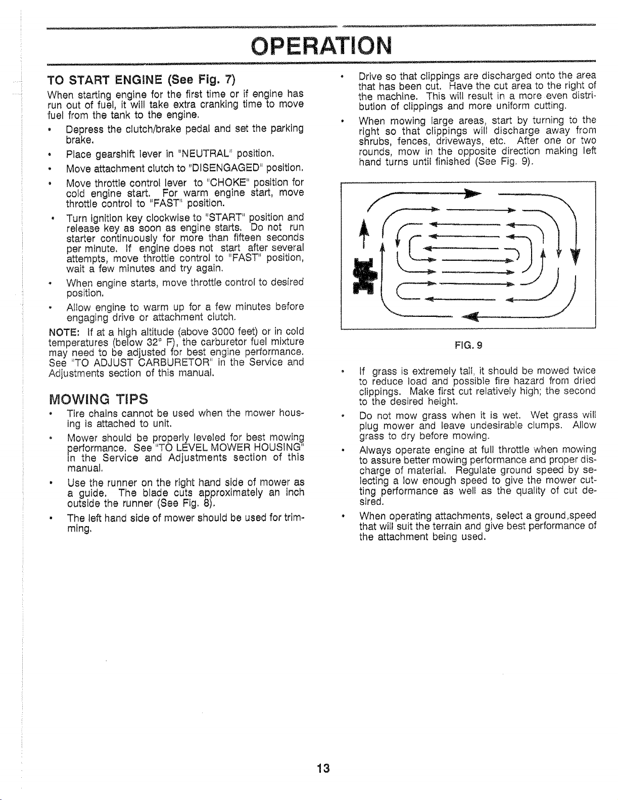
When mowing large areas, start by turning to the
right so that clippings will discharge away from
shrubs, fences, driveways, etc. After one or two
rounds, mow in the opposite direction making left
hand turns until finished (See Fig. 9).
FiG. 9
, tf grass is extremely tall, it should be mowed twice
to reduce load and possible fire hazard from dried
clippings. Make first cut relatively high; the second
to the desired height.
, Do not mow grass when it is wet. Wet grass wilI
plug mower and leave undesirable clumps. Allow
grass to dry before mowing.
, Always operate engine at full throttle when mowing
to assure better mowing performance and proper dis-
charge of material. Regulate ground speed by se-
lecting a Iow enough speed to give the mower cut-
ting performance as welt as the quality of cut de-
sired.
When operating attachments, select a ground_speed
that will suit the terrain and give best performance of
the attachment being used.
13
L
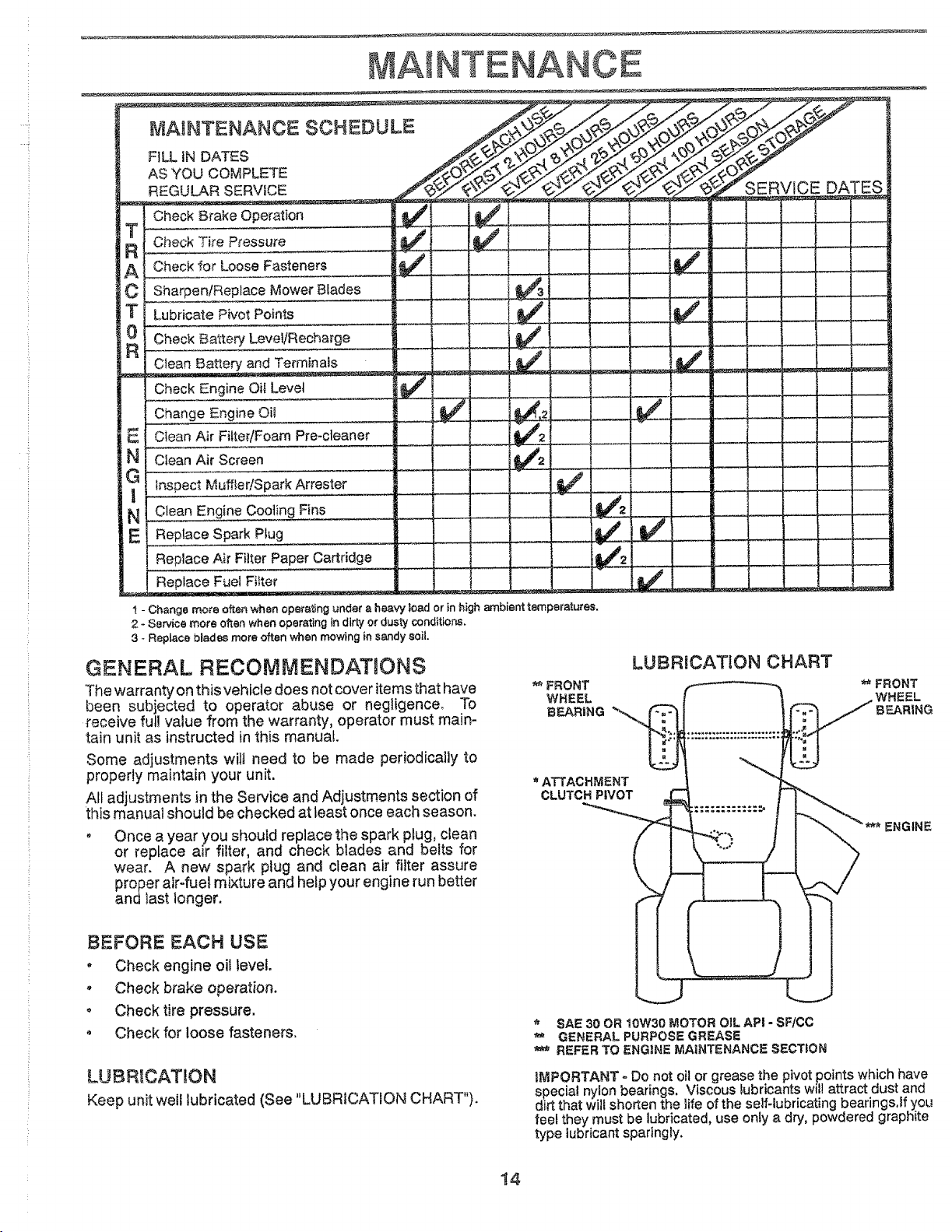
MAINTENANCE SCHEDULE
FILL fN DATES
AS YOU COMPLETE
REGULAR SERVICE
T
R
A
C
0
R
Check Brake Operation
Check Tire Pressure
Check _or Loose Fasteners
Sharpen!Replace Mower Blades
Lubricate Pivot Points
Check Battery Level/Recharge
Clean 8artery and Terminals
Check Engine Oil Level
Change Engine Oil
Clean Air Filter/Foam Pre-cleaner
Clean Air Screen
Inspect Muffler/Spark Arrester
Clean Engine Cooting Fins
Replace Spark Piug
Replace Air Filter Paper Cartridge
Replace Fuel Fi!ter
t - Change mc_e often when operating under a hee_
2 - Service more often when operating in dirty or dusty conditions.
3 - Replace blades more often when mowing in sandy 8oil.
, toad or in high ambient tern
GENERAL RECOMMENDATnONS
The warranty on this vehicle does not cover items that have
been subjected to operator abuse or negligence. To
receive full value from the warranty, operator must main-
tain unit as instructed inthis manual.
Some adjustments wilt need to be made periodically to
properly maintain your unit.
All adjustments in the Service and Adjustments section of
this manual should be checked at least once each season.
o Once a year you should replace the spark plug, clean
or replace air filter, and check blades and belts for
wear. A new spark plug and clean air filter assure
proper air-fuel mixture and help your engine run better
and_ast longer.
BEFORE EACH USE
, Check engine oil level.
- Check brake operation.
o Check tire pressure.
• Check for loose fasteners.
LUBR!CATION
Keep unit well lubricated (See "LUBRICATION CHART").
]
_era'{uree.
SERVICE DATES
LUBRICATION CHART
** FRONT
WHEEL
BFJ_RING
ATTACHMENT
CLUTCH PIVOT
** FRONT
WHEEL
BEARING
* 8AE 30 OR 10W30 MOTOR OiL API - SF/CC
GENERAL PURPOSE GREASE
REFER TO ENGINE MAINTENANCE SECTION
iMPORTANT - Do not oil or grease the pivot points which have
special nylon bearings. Viscous _ubricants wil! attract dust and
d rt that will shorten the life of the self-lubricating bearings.lf you
feel they must be lubricated, use only a dry, powdered graph te
type lubricant sparingly.
14
AINTENANCE
TRACTOR
Always observe safety rules when performing any mainte-
nance.
TIRES
, Maintain proper air pressure in att tires (See "PROD-
UCT SPECIFICATIONS" on page 3 of this manual).
, Keep tires free of gasoline, oil, or insect control chemi-
cals which can harm rubber.
• Avoid stumps, stones, deep ruts, sharp objects and
other hazards that may cause tire damage.
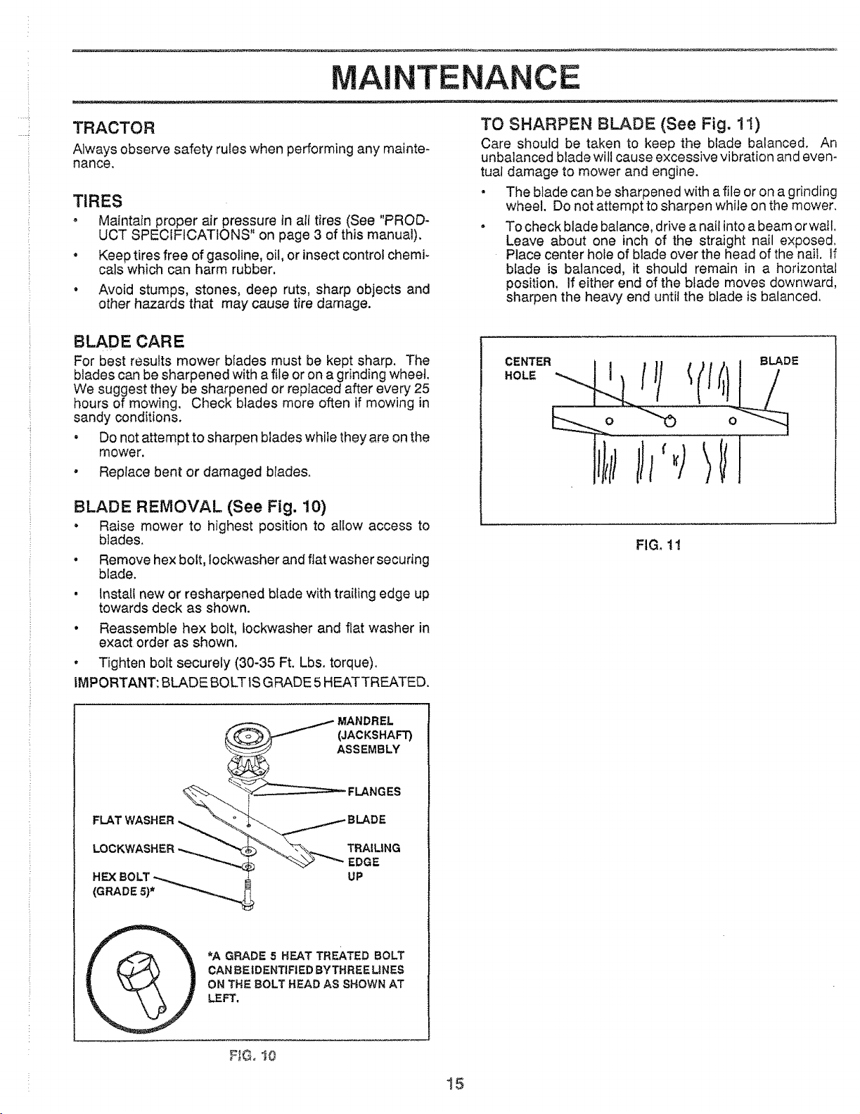
TO SHARPEN BLADE (See Fig. 11)
Care shoutd be taken to keep the blade balanced. An
unbalanced blade will cause excessive vibration and even-
tual damage to mower and engine.
, The blade can be sharpened with a file or on a grinding
wheel. Do not attempt to sharpen while on the mower.
• To check blade balance, drive a nail into a beam or wail.
Leave about one inch of the straight nail exposed.
Place center hole of blade over the head of the nail. If
blade is balanced, it should remain in a horizontal
position. If either end of the blade moves downward,
sharpen the heavy end until the blade is balanced,
BLADE CARE
For best results mower blades must be kept sharp. The
blades can be sharpened with a file or on a grinding wheel.
We suggest they be sharpened or replaced after every 25
hours of mowing. Check blades more often if mowing in
sandy conditions.
• Do not attempt to sharpen blades while they are on the
mower.
• Replace bent or damaged b{ades.
BLADE REMOVAL (See Fig. 10)
• Raise mower to highest position to allow access to
blades,
° Remove hex bolt, lockwasher and flat washer securing
blade,
• install new or resharpened blade with trailing edge up
towards deck as shown.
• Reassemble hex bolt, Iockwasher and flat washer in
exact order as shown.
° Tighten bolt securely (30-35 Ft. Lbs. torque).
iMPORTANT: BLADE BOLT iS GRADE 5 HEATTREATED.
FIG. 11
MANDREL
(JACKSHAF'r)
ASSEMBLY
FLAT WASHER
LOCKWASHER
FLANGES
TRAILING
EDGE
UP
*A GRADE 5 HEAT TREATED BOLT
CANBE IDENTIFIED BYTHREE LINES
ON THE 8OLT HEAD AS SHOWN AT
LEFT,
, ,G. i0
15
.....i
]
,4
]
MAINTENANCE
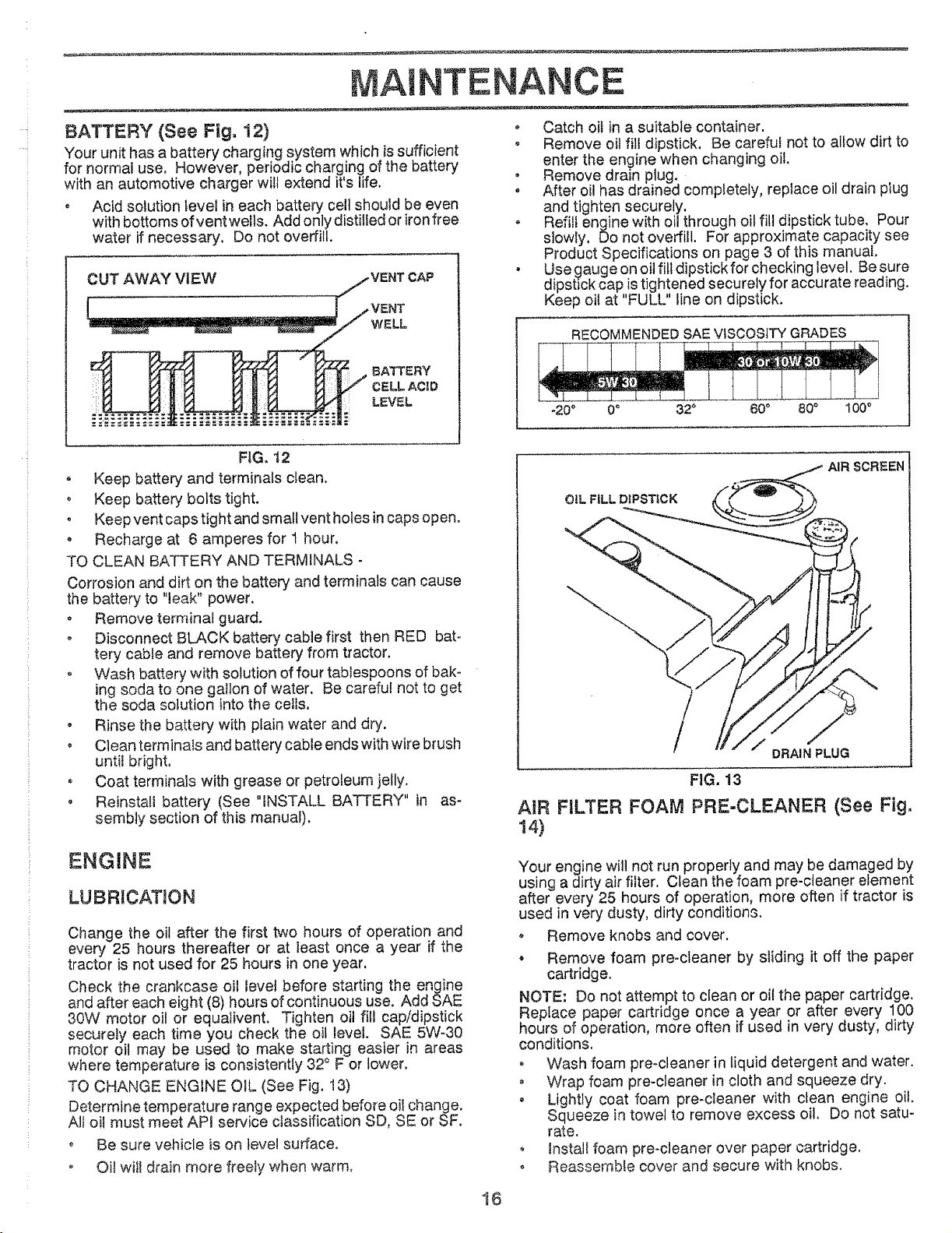
BATTERY (See Fig. 12)
Your unit has a battery charging system which is sufficient
for normal use. However, periodic charging of the battery
with an automotive charger wi!t extend it's life.
° Acid solution levet in each battery celt should be even
with bottoms of vent wells. Add only distilled or iron free
water if necessary, Do not overfill.
- Catch oil in a suitable container.
o Remove oil fil! dipstick. Be careful not to allow dirt to
enter the engine when changing oil,
, Remove drain plug.
, After oil has drained Completely, replace oil drain plug
and tighten securely.
o Refill engine with oil through oil fill dipstick tube, Pour
slowly, Do not overfill. For approximate capacity see
Product Specifications on page 3 of this manual,
, Use gauge on oil fill dipstick for checking level, Be sure
dipstick cap is tightened securely for accurate reading,
Keep oil at "FULU' line on dipstick,
RECOMMENDED SAE VISCOSITY GRADES
-20 ° 0 _ 32 _ 60 ° 80 ° 100 _
AIR SCREEN
FIG, t2
° Keep battery and terminals clean.
, Keep battery bolts tight.
• Keep vent caps tight and small vent holes in caps open.
Recharge at 6 amperes for 1 hour,
TO CLEAN BATTERY AND TERMINALS -
Corrosion and dirt on the battery' and terminals can cause
the battery to "leak" power.
• Remove terminal guard.
o Disconnect BLACK battery cable first then RED bat-
tery cable and remove battery from tractor.
o Wash bakery with solution of four tablespoons of bak-
ing soda to one gallon of water. Be careful not to get
the soda solution into the ceils,
• Rinse the battery with plain water and dry.
• Clean terminals and battery cable ends with wire brush
until bright,
° Coat terminals with grease or petroleum jelly,
, Reinstall battery (See "INSTALL BATTERY" in as-
sembly section of this manual).
ENGINE
LUBRICATION
Change the oil after the first two hours of operation and
even/ 25 hours thereafter or at least once a year if the
tractor is not used for 25 hours in one year.
Check the crankcase oil level before starting the engine
and after each eight (8) hours of continuous use, Add SAE
30W motor oil or equalivent, Tighten oil fill cap/dipstick
securely each time you check the oil level. SAE 5W-30
motor oil may be used to make starting easier in areas
where temperature is consistently 32 ° F or lower.
TO CHANGE ENGINE OIL (See Fig. t3)
Determine temperature rang e expected before oil change.
All oil must meet API service classification SD, SE or SF.
o Be sure vehicle is on level surface,
° Oil wil! drain more freely when warm,
!6
OIL FILL DIPSTICK
DRAIN PLUG
FIG. 13
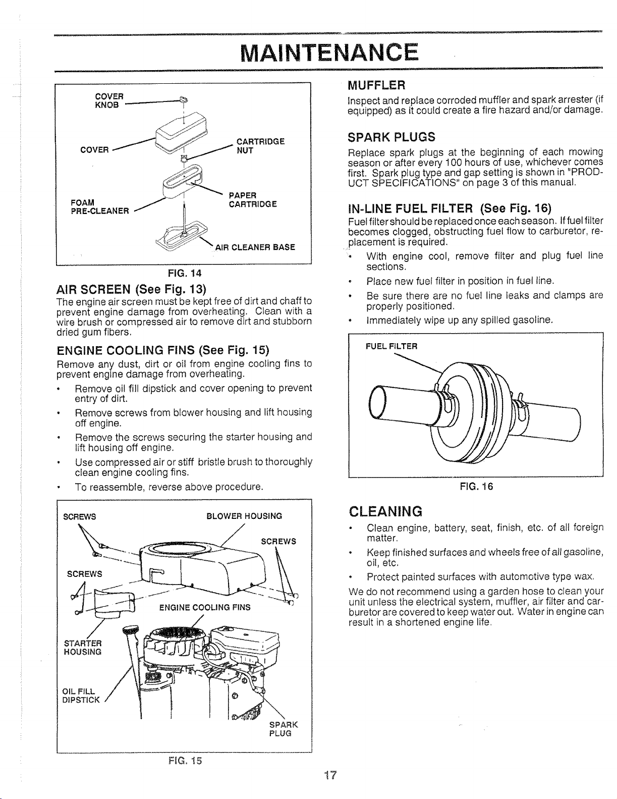
AiR FILTER FOAM PRE-CLEANER (See Fig,
14)
Your engine will not run properly and may be damaged by
using a dirty air filter, Clean the foam pre-cteaner element
after every 25 hours of operation, more often if tractor is
used in very dusty, dirty conditions,
o Remove knobs and cover.
• Remove foam pre-cleaner by sliding it off the paper
cartridge,
NOTE: Do not attempt to clean or oi! the paper cartridge,
Replace paper cartridge once a year or after every 100
hours of operation, more often if used in very dusty, dirty
conditions,
° Wash foam pre-cleaner in liquid detergent and water.
, Wrap foam pre-cleaner in cloth and squeeze dry.
, Lightly coat foam pre-cleaner with clean engine oil,
Squeeze in towel to remove excess oil, Do not satu-
rate,
, Install foam pre-cleaner over paper cartridge.
o Reassemble cover and secure with knobs.
MAI
TENANCE
COVER
KNOB "--" i
CARTRIDGE
oov .
_ PAPER
PRE-CLEANERFOAMJ i CARTRI DG E
_ 1t°..
__ AIR CLEANER BASE
FIG. 14
AIR SCREEN (See Fig. 13)
The engine air screen must be kept free of dirt and chaff to
prevent engine damage from overheating. Clean with a
wire brush or compressed air to remove dirt and stubborn
dried gum fibers,
ENGINE COOLING FINS (See Fig. 15)
Remove any dust, dirt or oil from engine cooling fins to
prevent engine damage from overheating.
, Remove oil fill dipstick and cover opening to prevent
entry of dirt.
• Remove screws from blower housing and lift housing
off engine.
• Remove the screws securing the starter housing and
lift housing off engine.
, Use compressed air or stiff bristle brush to thoroughly
clean engine cooling fins,
• To reassemble, reverse above procedure.
MUFFLER
Inspect and replace corroded muffler and spark arrester (if
equipped) as it could create a fire hazard and/or damage,
SPARK PLUGS
Replace spark plugs at the beginning of each mowing
season or after every 100 hours of use, whichever comes
first. Spark plug type and gap setting is shown in "PROD-
UCT SPECIFICATIONS" on page 3 of this manual.
IN-LINE FUEL FILTER (See Fig. 16)
Fuel filter should be replaced once each season. Iffuel filter
becomes clogged, obstructing fuel flow to carburetor, re-
,placement is required.
', With engine cool, remove filter and plug fuel line
sections.
. Place new fuel filter in position in fuel line.
• Be sure there are no fuel line leaks and clamps are
properly positioned,
• Immediately wipe up any spilled gasoline.
FUEL FILTER
FIG. 16
SCREWS BLOWER HOUSING
SCREWS
STARTER
HOUSING
OIL FILL
DIPSTICK
ENGINECOOLING FINS
SCREWS
SPARK
PLUG
CLEANING
• Clean engine, battery, seat, finish, etc. of all foreign
matter,
. Keep finished surfaces and wheels free of all gasoline,
oil, etc,
• Protect painted surfaces with automotive type wax,
We do not recommend using a garden hose to clean your
unit unless the electrical system, muffler, air filter and car-
buretor are covered to keep water out, Water in engine can
result in a shortened engine life.
FEG, I8
!7
i
SERVICE AN ADJUSTMENTS
CAUTION: BEFORE PERFORMING ANY SERVICE OR ADJUSTMENTS:
• Depress clutch/brake pedal fully and set parking brake.
• Place gearshift lever in "NEUTRAL" position.
• Place attachment clutch in "DISENGAGED" position.
o Turn ignition key "OFF" and remove key.
• Make sure the blades and atl moving parts have completely stopped.
• Disconnect spark plug wire from spark plug and place wire where it cannot come in contact with
plug,
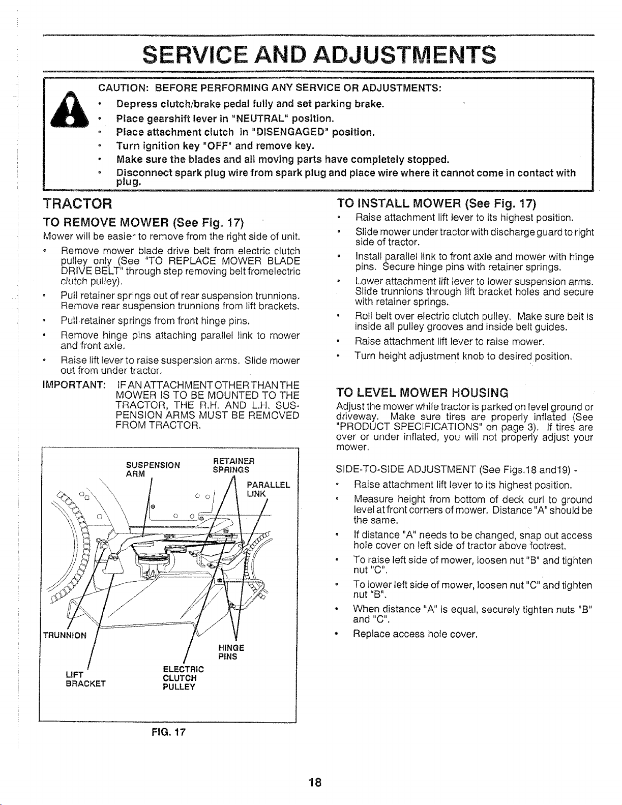
TRACTOR
TO REMOVE MOWER (See Fig. 17)
Mower wil! be easier to remove from the right side of unit.
, Remove mower blade drive belt from electric clutch
pulley only (See "TO REPLACE MOWER BLADE
DRIVE BELT" through step removing belt fromelectric
clutch pulley).
o Pull retainer springs out of rear suspension trunnions°
Remove rear suspension trunnions from lift brackets,
, Pull retainer springs from front hinge pins,
, Remove hinge pins attaching parallel link to mower
and front axle,
Raise lift lever to raise suspension arms. Slide mower
out from under tractor.
]FAN ATTACHMENT OTHER THAN THE
MOWER IS TO BE MOUNTED TO THE
TRACTOR, THE R.H. AND L.H. SUS-
PENSION ARMS MUST BE REMOVED
FROM TRACTOR,
IMPORTANT:
TO INSTALL MOWER (See Fig. 17)
• Raise attachment lift ]ever to its highest position,
• Slide mower under tractor with discharge guard to right
side of tractor.
, Install parallel link to front axle and mower with hinge
pins. Secure hinge pins with retainer springs.
, Lower attachment lift lever to tower suspension arms.
Slide trunnions through lift bracket holes and secure
with retainer springs.
• Roll belt over electric clutch pulley, Make sure belt is
inside all pulley grooves and inside belt guides.
• Raise attachment lift lever to raise mower.
, Turn height adjustment knob to desired position.
TO LEVEL MOWER HOUSING
Adjust the mower while tractor is parked on level ground or
driveway. Make sure tires are properly inflated {See
"PRODUCT SPECIFICATIONS" on page 3). If tires are
over or under inflated, you will not properly adjust your
mower.
TRUNNION
LIFT
BRACKET
SUSPENSION RETAINER
ARM SPRINGS
ELECTRIC
CLUTCH
PU LLEY
O O
O
PARALLEL
LINK
HINGE
PINS
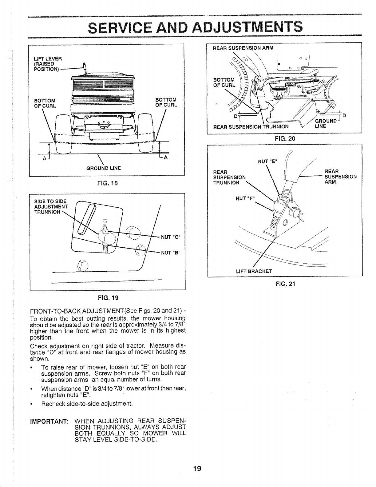
SIDE-TO-SIDE ADJUSTMENT (See Figs,18 and19) -
, Raise attachment lift lever to its highest position.
• Measure height from bottom of deck curl to ground
leveeat front corners of mower. Distance "A" should be
the same.
• If distance "A" needs to be changed, snap out access
hole cover on left side of tractor above footrest,
, To raise left side of mower, loosen nut "B" and tighten
nut "C".
• To lower left side of mower, loosen nut "C" and tighten
nut "B".
When distance "A" is equal, securely tighten nuts "B"
and "C",
Replace access hole cover.
FIG. 17
18
.... !
SERVICE A
D ADJUSTMENTS
LIFT LEVER
(RAISED
POSITION)
BOTTOM BOTTOM
OF CURL L OF CURL
\
GROUND LINE
FIG, 18
SIDE TO SIDE
ADJUSTMENT
TRUNNION _
_!NUT
_- NUT
.............J
p_C _1
I;B_I
FIG. 19
FRONT-TO-BACK ADJUSTMENT(See Figs, 20 and 21) -
To obtain the best cutting results, the mower housing
should be adjusted so the rear is approximately 3/4 to 7/8"
higher than the front when the mower is in its highest
position,
Check adjustment on right side of tractor, Measure dis-
tance "D" at front and rear flanges of mower housing as
shown.
• To raise rear of mower, loosen nut "E" on both rear
suspension arms. Screw both nuts "F" on both rear
suspension arms an equal number of turns,
• When distance "D" is 3/4 to 7/8" lower at front than rear,
retighten nuts "E",
o Recheck side-to-side adjustment.
REAR SUSPENSION ARM
\
\
\\
\
oo/
BOTTOM
OF CURL
DT-----
REARSUSPENSIONTRUNNION
FIG, 20
LINE
REAR
SUSPENSION
TRUNNION
LIFTBRACKET
FIG, 21
REAR
SUSPENSION
ARM
IMPORTANT:
WHEN ,ADJUSTING REAR SUSPEN-
SION TRUNNIONS, ALWAYS ADJUST
BOTH EQUALLY SO MOWER WILL
STAY LEVEL SIDE-TO-SIDE.
19
!
SERVICE AN
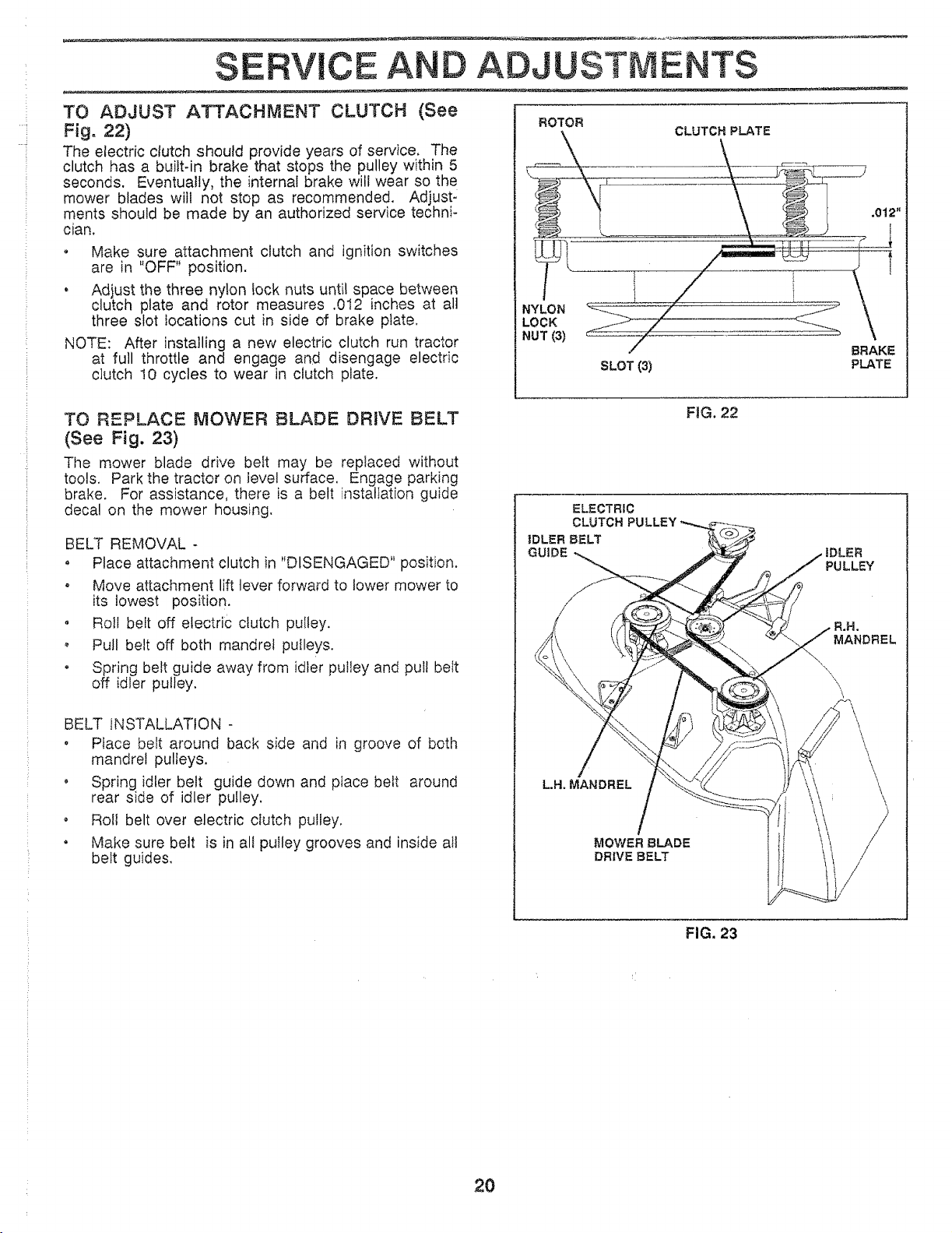
TO ADJUST ATTACHMENT CLUTCH (See
Fig. 22)
The electric clutch should provide years of service. The
clutch has a built-in brake that stops the pulley within 5
seconds. Eventually, the internal brake will wear so the
mower blades witl not stop as recommended. Adjust:
ments should be made by an authorized service techni-
cian.
o Make sure attachment clutch and ignition switches
are in "OFF" position.
, Adjust the three ny!on rock nuts until space between
clutch plate and rotor measures .012 inches at all
three slot locations cut in side of brake plate.
NOTE: After installing a new electric clutch run tractor
at full throttle and engage and disengage electric
clutch t0 cycles to wear in clutch plate.
ADJUSTMENTS
ROTOR
CLUTCH PLATE
NYLON
LOCK
NUT (3)
SLOT (3)
.012"
BRAKE
PLATE
TO REPLACE MOWER BLADE DRIVE BELT
(See Fig. 23)
The mower blade drive belt may be replaced without
tools. Park the tractor on level surface. Engage parking
brake. For assistance, there is a belt instaltatEon guide
decal on the mower housing.
BELT REMOVAL -
• Place attachment clutch in "DISENGAGED" position.
• Move attachment lift lever forward to lower mower to
its lowest position.
o Roll belt off electric clutch pulley.
o Pull belt off both mandrel pulleys.
• Spring belt guide away from idler pulley and pull belt
off idler pulley.
BELT INSTALLATION -
, Place belt around back side and in groove of both
mandrel pulleys.
o Spring idler belt guide down and place belt around
rear side of idler pulley.
o Roll belt over electric clutch pulley.
, Make sure belt is in all pulley grooves and inside all
belt guides.
FIG. 22
ELECTRIC
CLUTCH
IDLER BELT
GUIDE IDLER
PULLEY
L.H. MANDREL
MOWER 8LADE
DRIVE BELT
a,a,
MANDREL
FIG. 23
2O
]
SERVICE A
D AOJUSTMENTS
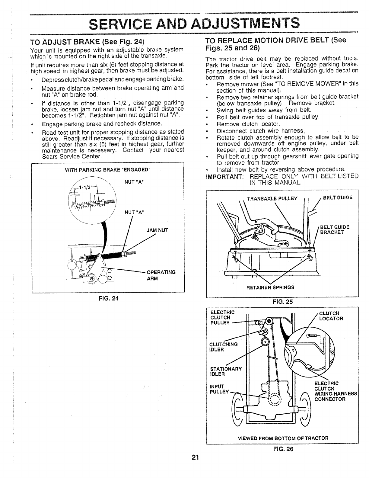
TO ADJUST BRAKE (See Fig. 24)
Your unit is equipped with an adjustable brake system
which is mounted on the right side of the transa×le.
If unit requires more than six (6) feet stopping distance at
high speed in highest gear, then brake must be adjusted;
• Depress clutch!brake pedal and engage parking brake,
o Measure distance between brake operating armand
nut "A" on brake rod.
• If distance is other than i-1/2", disengage parking
brake, loosen jam nut and turn nut "A" until distance
becomes 1-1/2". Retighten jam nut against nut "A",
o Engage parking brake and recheck distance,
o Road test unit for proper stopping distance as stated
above. Readjust if necessary. If stopping distance is
still greater than six (6) feet in highest gear, further
maintenance is necessary. Contact your nearest
Sears Service Center,
WITH PARKING BRAKE "ENGAGED"
JAM NUT
OPERATING
ARM
NUT "A"
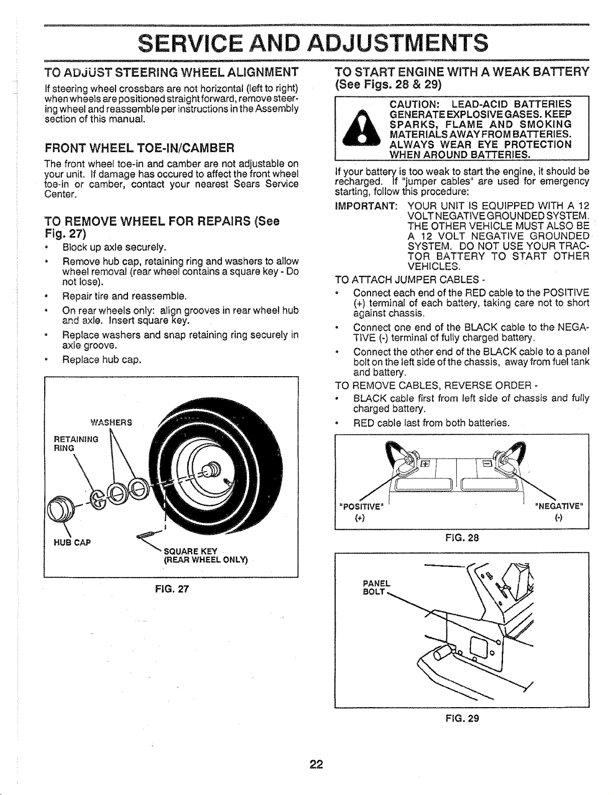
TO REPLACE MOTION DRIVE BELT (See
Figs. 25 and 26)
The tractor drive belt may be replaced without tools,
Park the tractor on level area, Engage parking brake.
For assistance, there is a belt installation guide decal on
bottom side of left footrest.
• Remove mower (See "TO REMOVE MOWER" in this
section of this manual).
• Remove two retainer springs from belt guide bracket
(below transaxle pulley), Remove bracket,
° Swing belt guides away from belt.
° Roll belt over top of transaxie pulley.
• Remove clutch locator.
o Disconnect clutch wire harness.
o Rotate clutch assembly enough to allow belt to be
removed downwards off engine pulley, under belt
keeper, and around clutch assembly,
• Pull belt out up through gearshift lever gate opening
to remove from tractor.
• Install new belt by reversing above procedure.
IMPORTANT: REPLACE ONLY WITH BELT LISTED
IN THIS MANUAL.
_ _ IBELTGUIDE.TRANSAXLE PULLEY / BELT GUIDE
RETAINER SPRINGS
FIG. 24
FIG. 25
ELECTRIC ,CLUTCH
CLUTCH LOCATOR
PULLEY
CLUTCHING
iDLER
STATIONARY
iDLER
INPUT
ELECTRIC
CLUTCH
WIRING HARNESS
CONNECTOR
VIEWED FROM BOTTOM OF TRACTOR
FIG. 26
21
i
SERVICE A ADJUSTMENTS
TO ADJUST STEERING WHEEL ALIGNMENT
tf steering wheel crossbars are not horizontal (left to right)
when wheels are positioned straightforward, remove steer-
ing wheel and reassemble per instructions in the Assembly
section of this manual.
FRONT WHEEL TOE-IN/CAMBER
The front wheel toe-in and camber are not adjustable on
your unit. If damage has occured to affect the front wheel
toe-in or camber, contact your nearest Sears Service
Center.
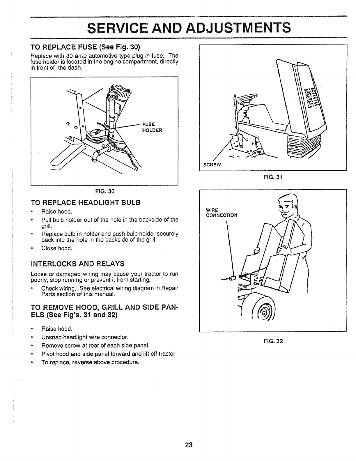
TO REMOVE WHEEL FOR REPAIRS (See
Fig. 27)
, Block up axle securely.
• Remove hub cap, retaining ring and washers to atiow
wheel removal (rear wheel contains a square key - Do
not lose).
• Repair tire and reassemble.
o On rear wheels on!y: align grooves in rear wheel hub
and axle. Insert square key.
= Replace washers and snap retaining ring securely in
axle groove.
o Replace hub cap.
WASHERS
RETAINING
RING
HUB CAP
!
_ SQUARE KEY
(REAR WHEEL ONLY)
FIG. 27
TO START ENGINE WITH A WEAK BATTERY
(See Figs. 28 & 29)
CAUTION: LEAD-ACID BATTERIES
GENERATEEXPLOSIVEGASES. KEEP
SPARKS, FLAME AND SMOKING
MATERIALS AWAY FROM BATTERIES.
ALWAYS WEAR EYE PROTECTION
WHEN AROUND BATTERIES.
if your battery is too weak to start the engine, it should be
recharged. If "jumper cables" are used for emergency
starting, follow this procedure:
IMPORTANT: YOUR UNIT tS EQUIPPED WITH A 12
VOLT NEGATIVEGROUNDED SYSTEM.
THE OTHER VEHICLE MUST ALSO BE
A 12 VOLT NEGATIVE GROUNDED
SYSTEM. DO NOT USE YOUR TRAC-
TOR BATTERY TO START OTHER
VEHICLES.
TO ATTACH JUMPER CABLES -
o Connect each end of the RED cable to the POSITIVE
(+) terminal of each battery, taking care not to short
against chassis.
• Connect one end of the BLACK cable to the NEGA-
TIVE (-) terminal of fully charged battery.
• Connect the other end of the BLACK cable to a panel
bolt on the left side of the chassis, away from fuel tank
and battery.
TO REMOVE CABLES, REVERSE ORDER -
• BLACK cabfe first from left side of chassis and fully
charged battery.
• RED cable last from both batteries.
FIG. 28
PANEL
FIG. 29
z 22
.....i
CEA ADJUSTM
NTS
TO REPLACE FUSE (See Fig. 30)
Replace with 30 amp automotive-type plug-in fuse. The
fuse holder is located in the engine compartment, directly
in front of the dash,
FUSE
HOLDER
i
SCREW
FIG, 31
FIG. 30
TO REPLACE HEADLIGHT BULB
• Raise hood.
• Pull bulb holder out of the hole in the backside of the
grill.
" Replace bulb in holder and push bulb holder securely
back into the hole in the backside of the grill.
• Close hood.
INTERLOCKS AND RELAYS
Loose or damaged wiring may cause your tractor to run
poorly, stop running or prevent it from starting.
• Check wiring. See electrical wiring diagram in Repair
Parts section of this manual.
TO REMOVE HOOD, GRILL AND SIDE PAN=
ELS (See Fig's. 31 and 32)
• Raise hood.
• Unsnap headlight wire connector.
• Remove screw at rear of each side panel.
° Pivot hood and side panel forward and lift off tractor,
• To replace, reverse above procedure.
WIRE
CONNECTION --
FIG. 32
23
:i
:i
SERVICE AND ADJUSTMENTS
ENGINE
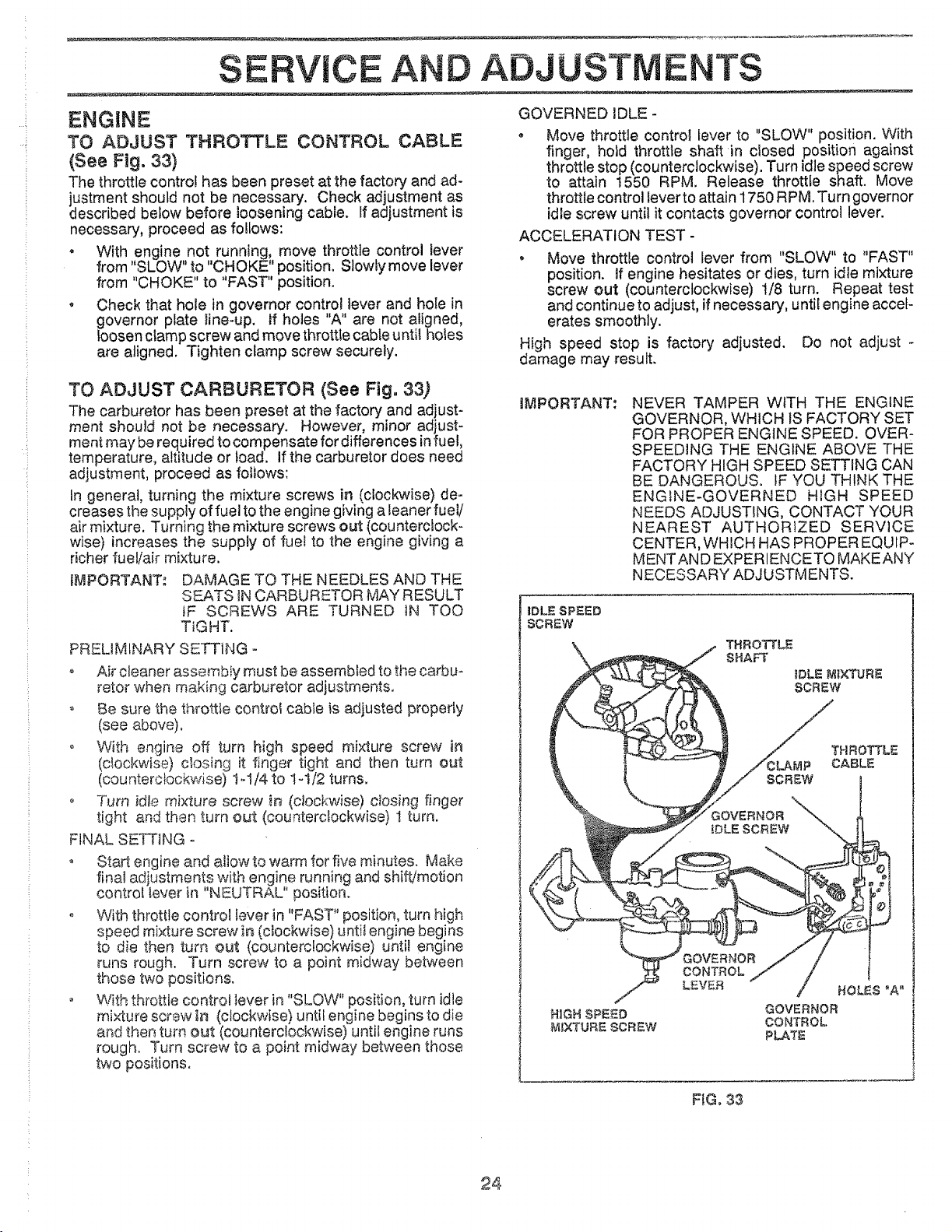
TO ADJUST THROTTLE CONTROL CABLE
(See Fig. 33)
The throttle control has been preset at the factory and ad-
justment should not be necessary. Check adjustment as
described below before loosening cable. If adjustment is
necessary, proceed as fo!lows:
GOVERNED IDLE -
• Move throttle control lever to "SLOW" position. With
finger, hoid throttle shaft in closed position against
throttle stop (counterclockwise). Turn idle speed screw
to attain 1550 RPM. Release throttle shaft. Move
throttle control lever to attain 1750 RPM. Turn governor
idle screw until it contacts governor control lever.
ACCELERATION TEST -
With engine not running, move throttle control lever
from "SLOW" to "CHOKE" position. Slowly move lever
from "CHOKE" to "FAST" position.
Check that hole in governor control lever and hole in
governor plate line-up. If holes "A" are not aligned,
loosen clamp screw and move throttle cable until holes
are aligned. Tighten clamp screw securely.
• Move throttte control lever from "SLOW" to "FAST"
position, if engine hesitates or dies, turn idle mixture
screw out (counterclockwise) 1/8 turn. Repeat test
and continue to adjust, if necessary, until engine accel-
erates smoothly.
High speed stop is factory adjusted. Do not adjust -
damage may result.
TO ADJUST CARBURETOR (See Fig. 33)
The carburetor has been preset at the factory and adjust-
ment should not be necessary. However, minor adjust-
ment may be required to compensate for differences in fuel,
temperature, altitude or load. If the carburetor does need
adjustment, proceed as fotiows:
tn general, turning the mixture screws in (clockwise) de-
creases the supply of fuel to the engine giving a feaner fuel/
air mixture. Turning the mixture screws out (counterclock-
wise) increases the supply of fuel to the engine giving a
richer fuel/air mixture.
IMPORTANT: DAMAGE TO THE NEEDLES AND THE
SEATS IN CARBURETOR MAY RESULT
IF SCREWS ARE TURNED IN TOO
TIGHT.
PRELIMINARY SETTING -
o Air cleaner assembly must be assembled to the carbu-
retor when making carburetor adjustments.
o Be sure the throttle controf cable is adjusted properly
(see above).
o With engine off turn high speed mixture screw in
(clockwise) closing it finger tight and then turn out
(counterclockwise) !-1/4 to 1°1/2 turns.
o Turn idle mixture screw in (clockwise) ctosing finger
tight and then turn out (counterclockwise) t turn.
FINAL SETTING o
o Start engine and allow to warm for five minutes. Make
final adjustments with engine running and shift/motion
control lever in "NEUTRAL" position.
o With throttle control lever in "FAST" position, turn high
r _ e
speed mixture sc. ew in (clockwise) until engin, begins
to die then turn out (counterclockwise) until engine
runs rough. Turn screw to a point midway between
those two positions.
With throttle control lever in "SLOW" position, turn idle
mixture screw in (clockwise) until engine begins to die
and then turn out (counterclockwise) until engine runs
rough. Turn screw to a point midway between those
two positions.
iMPORTANT: NEVER TAMPER WITH THE ENGINE
GOVERNOR, WHICH IS FACTORY SET
FOR PROPER ENGINE SPEED. OVERt
SPEEDING THE ENGINE ABOVE THE
FACTORY HIGH SPEED SETTING CAN
BE DANGEROUS. iF YOU THINK THE
ENGINE-GOVERNED H_GH SPEED
NEEDS ADJUSTING, CONTACT YOUR
NEAREST AUTHORIZED SERVICE
CENTER, WHICH HAS PROPER EQUIP-
MENTAN D EXPERIENCETO MAKEANY
NECESSARY ADJUSTMENTS.
IDLE SPEED
SCREW
\
THROTTLE
SHAFT
IDLE MIXTURE
SCREW
THROTTLE
.AMP CABLE
HIGH SPEED
MIXTURE SCREW
GOVERNOR
CONTROL
LEVE_
HOLES "A"
GOVERNOR
CONTROL
PLATE
FIG, 33
24
STORAGE
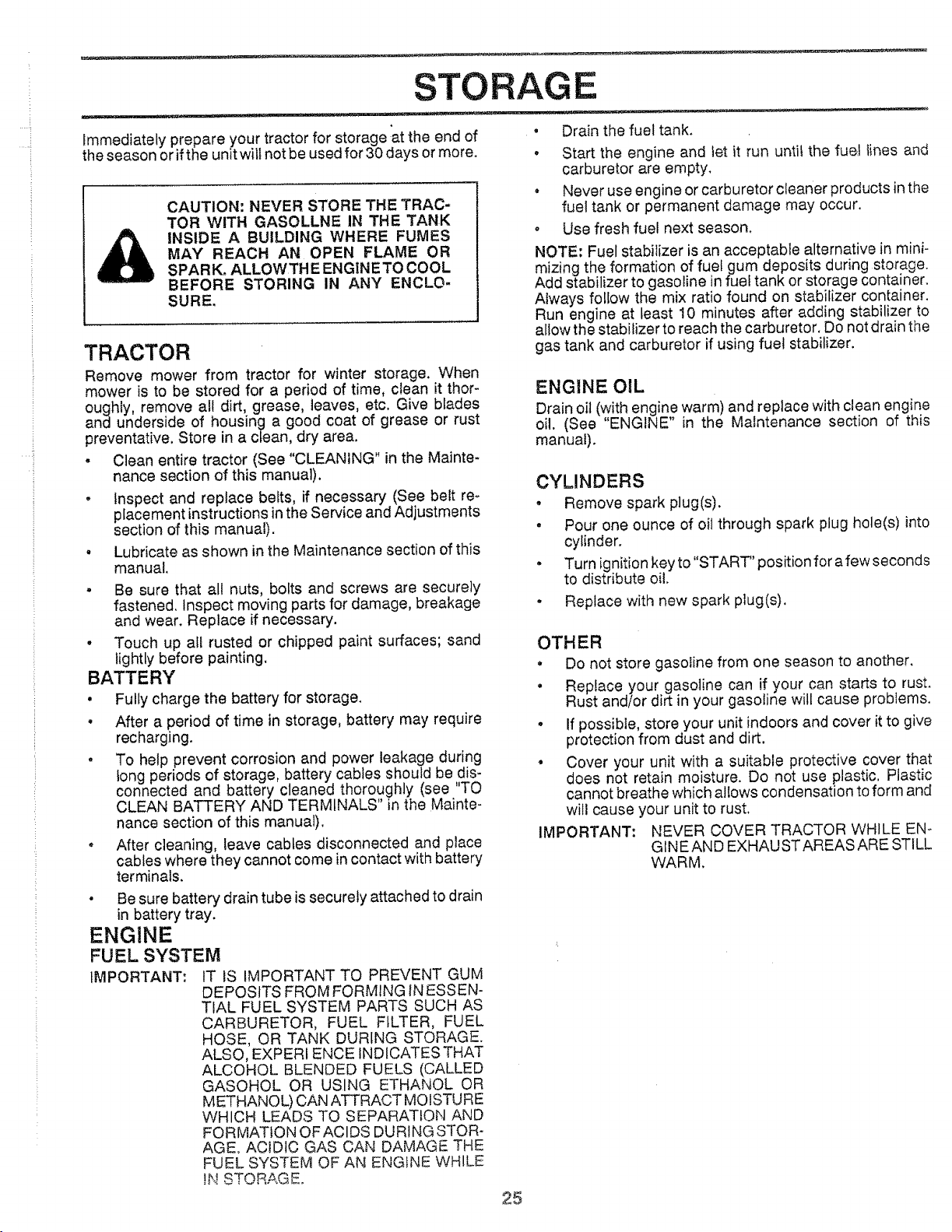
Immediately prepare your tractor for storage at the end of
the season or if the unit wilt not be used for 30 days or more.
CAUTION: NEVER STORE THE TRAC-
TOR WITH GASOLLNE IN THE TANK
INSIDE A BUILDING WHERE FUMES
MAY REACH AN OPEN FLAME OR
SPARK, ALLOWTHE ENGI[NETO COOL
BEFORE STORING IN ANY ENCLO-
SURE,
TRACTOR
Remove mower from tractor for winter storage, When
mower is to be stored for a period of time, clean it thor-
oughly, remove all dirt, grease, leaves, etc. Give blades
and underside of housing a good coat of grease or rust
preventative. Store in a clean, dry area.
• Clean entire tractor (See "CLEANING" in the Mainte-
nance section of this manual).
, Inspect and replace belts, if necessary (See belt re-
placement instructions in the Service and Adjustments
section of this manual).
, Lubricate as shown in the Maintenance section of this
manual.
" Be sure that all nuts, bolts and screws are securely
fastened. Inspect moving parts for damage, breakage
and wear. Replace if necessary.
• Touch up all rusted or chipped paint surfaces; sand
lightly before painting,
BATTERY
• Fully charge the battery for storage.
, After a period of time in storage, battery may require
recharging.
o To help prevent corrosion and power leakage during
tong periods of storage, battery cables should be dis-
connected and battery cleaned thoroughly (see 'TO
CLEAN BATTERY AND TERMINALS" in the Mainte-
nance section of this manual).
• After cleaning, leave cables disconnected and place
cables where they cannot come in contact with battery
terminals.
, Drain the fuel tank.
, Start the engine and fet it run until the fuel lines and
carburetor are empty.
* Never use engine or carburetor cleaner products in the
fuel tank or permanent damage may occur.
, Use fresh fuel next season.
NOTE: Fuel stabilizer is an acceptable alternative in mini-
mizing the formation of fuetgum deposits during storage.
Add stabilizer to gasoline in fuel tank or storage container.
Always follow the mix ratio found on stabilizer container.
Run engine at least 10 minutes after adding stabilizer to
allow the stabilizer to reach the carburetor. Do not drain the
gas tank and carburetor if using fuel stabilizer.
ENGtNE OIL
Drain oil (with engine warm) and replace with clean engine
oil. (See "ENGINE" in the Maintenance section of this
manual).
CYLINDERS
. Remove spark plug(s).
• Pour one ounce of oil through spark plug hole(s) into
cylinder.
• Turn ignition key to "START' position for afew seconds
to distribute oil.
. Replace with new spark plug(s).
OTHER
• Do not store gasoline from one season to another.
• Replace your gasoline can if your can starts to rust.
Rust and/or dirt in your gasoline will cause problems.
• If possible, store your unit indoors and cover it to give
protection from dust and dirt.
° Cover your unit with a suitable protective cover that
does not retain moisture. Do not use plastic. Plastic
cannot breathe which allows condensation to form and
will cause your unit to rust.
IMPORTANT: NEVER COVER TRACTOR WHILE EN o
GINEAND EXHAUSTAREAS ARE STILL
WARM.
, Be sure battery drain tube is securely attached to drain
in battery tray.
ENGINE
FUEL SYSTEM
IMPORTANT: IT IS IMPORTANT TO PREVENT GUM
DEPOSITS FROM FORMING iNESSEN-
TIAL FUEL SYSTEM PARTS SUCH AS
CARBURETOR, FUEL FILTER, FUEL
HOSE, OR TANK DURING STORAGE.
ALSO, EXPER! ENCE INDICATES THAT
ALCOHOL BLENDED FUELS (CALLED
GASOHOL OR USING ETHANOL OR
METHANOL) CAN ATTRACT MOISTURE
WHICH LEADS TO SEPARATION AND
FORMATION OF ACIDS DURING STOR-
AGE° ACiDiC GAS CAN DAMAGE THE
FUEL SYSTEM OF AN ENGINE WHILE
_N STORAGE.
25

PROBLEM
WHI not start
Hard to start
Engine will not turn over
Engine clicks but will not
start
Loss of power
Excessive vibration
TROU LESHOOTI
CAUSE
1. Out of rue!.
2. Engine not "CHOKED" properly.
3. Engine flooded.
4. Bad spark plug.
5. Dirty air filter.
6, Dirty fuel filter.
7, Water in fuel.
8. Loose or damaged wiring.
9. Carburetor out of adjustment.
!0. Engine valves out of adjustment.
t. Dirty air fliter.
2. Bad spark plug.
3o Weak or dead battery.
4, Dirty fue_filter.
5. Stale or dirty fuel
6. Loose or damaged wiring.
7. Carburetor out of adjustment.
8. Engine valves out of adjustment.
1. Clutch/brake pedal not depressed.
2. Attachment clutch is engaged.
3. Spark plug wire is disconnected;
4. Weak or dead battery.
5. Blown fuse.
6. Corroded battery terminals.
7. Loose or damaged wiring.
8. Faulty ignition switch.
9. Faulty solenoid or starter.
10. Faulty operator presence switch(es).
1. Weak or dead battery.
2, Corroded battery terminals.
3. Loose or damaged wiring.
4. Faulty solenoid or starter.
1. Cutting too much grass.ffoo fast.
2, Throttle in "CHOKE" position.
3. Build-up of grass. _eaves and trash under mower.
4. Dirty air filter.
5. Low oil level/dirty oil.
6. Faulty spark plug.
7, Dirty fuel filter,
8. State or di_y fuel.
9. Water in fuel.
10. Spark plug wire loose.
11. Dirty engine air screen/fins.
!2. Dirty/clogged muffler.
18. Loose or damaged wiring.
14. Carburetor out of adjustment.
15. Engine valves out of adjustment.
1. Worn, bent or loose blade.
2. Bent blade mandrel,
3. Loose/damagedpart(s),
G POINTS
CORRECTION
1. Fillfueltank.
2. See TO START ENGINE' in operation section.
3. Wait several minutes before attempting to start.
4. Replace spark p{ug.
5. Clean/replace air filter.
6. Replace fuelfliter.
7. Drain fuel tank and carburetor, refill tank with fresh
gasoline and replace fuel filter.
8. Check aft wiring.
g. Contact Sears Service Department.
10. Contact Sears Service Department.
1. Clean/replace air filter.
2, Replace spark plug.
8. Rechargeor replace batter€.
4. Replace fuel filter.
5. Drain fuel tank and refill with fresh gasoline.
6. Check all wiring.
7. Contact Sears Service Department.
8. Contact Sears Service Department.
t. Depress Clutch/brake pedal.
2. Disengage attachment c_utch.
3. Connect wire to spark plug,
4, Recharge or replace battery,
5, Replace fuse.
6, Clean battery terminals.
7. Check all wiring.
8. Check/replace ignition switch.
9. Check/replace solenoid or starter.
!0. Contact Sears Service Department.
1. Recharge or replace battery.
2. Clean battery terminals.
3. Check all wiring.
4, Check/replace solenoid or starter,
1. Set in "Higher Cut" position/reduce speed.
2. Adjust throttle control.
& Clean underside of mower housing.
4. Clean/replace air filter.
5. Check oil level/change oil.
6. C]ean and regap or change spark plug.
7. Replace fuel filter.
8. Drain fuel tank and refill with fresh gasoline.
9. Drain fuel tank and carburetor, refill tank with fresh
gasoline and replace fuel filter.
t0. Connect and tighten spark plug wire.
tl. Clean engine air screen/fins.
12. Cleanlreplace muffler.
13. Check all wiring.
14. Contact Sears Service Department.
l& Contact Authorized Service Facility.
I. Replace blade. Tighten blade bolt.
:2, Replace blade mandrel
3. Tighten loose part(s). Replace damaged parts.
26
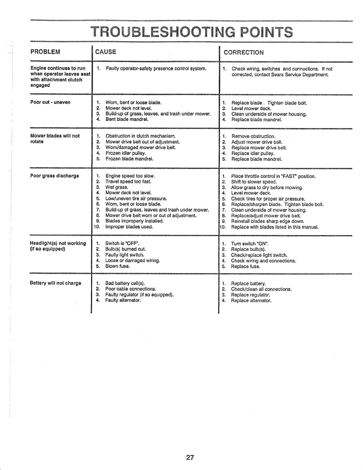
......!
TROUBLESHOOTING POINTS
PROBLEM CAUSE CORRECTION
: Engine continues to run I. Faulty operator-safety presence control system. 1. Check wiring, switches and connections. If not
when operator |eaves saat corrected, contact Sears Service Department.
with attachment clutch
engaged
Poor cut - uneven 1. Worn. bent or loose blade. 1. Replace blade. Tighten blade boil
2. Mower deck not level 2. Level mower deck.
3. Build-up of grass, leaves, and trash under mower. 3. Ctean underside of mower housing.
4. Bent blade mandrel. 4. Replace blade mandrel.
Mower blades will not t. Obstruction in clutch mechanism. 1_ Remove obstruction.
rotate 2, Mower drive belt out of adjustment. 2. Adjust mower drive belt.
3. Worntdamaged mower drive belt. 3. Replace mower drive belt.
4. Frozen idler pulley. 4. Replace idler pulley.
5. Frozen blade mandrel. 5_ Replace blade mandrel.
Poor grass discharge !. Engine speed too slow. I. Place throttle control in "FAST" position.
2. Travet speed too fast. 2. Shift to slower speed.
3. Wet grass. 3. ALlow grass to dry before mowing.
4. Mower deck not level. 4. Level mower deck.
5. Lowluneven tire air pressure. 5. Check tires for proper air pressure.
6. Worn, bent or loose blade. 6. Replace/sharpen blade. Tighten blade bolt.
7. Build-up of grass, leaves and trash under mower. 7. Clean underside of mower housing.
8. Mower drive beat worn or out of adjustment. 8. Replace/adjust mower drive belt.
9. Blades improperly installed. 9. Reinstall bfades sharp edge down.
10. Improper blades used. t0. Reptace with blades listed in this manual
Headlight(s} not working I, Switch is"OFF", t. Turn switch "ON".
(if SO equipped) 2. Bulb(S) burned out. 2. Replace bulb(s).
3. Faulty light switch. 3. Check/replace light switch.
4. Loose or damaged wiring. 4. Check wiring and connections.
5. Blown fuse. 5. Replace fuse.
Battery will not charge 1. Bad battery cell(s). 1. Replace battery.
2. Poor cable connections. 2. Check/clean all connections.
3. Faulty regulator (if so equipped). 3. Replace regulator.
4. Faulty alternator. 4. Replace alternator.
27

SERVICE NOTES
28
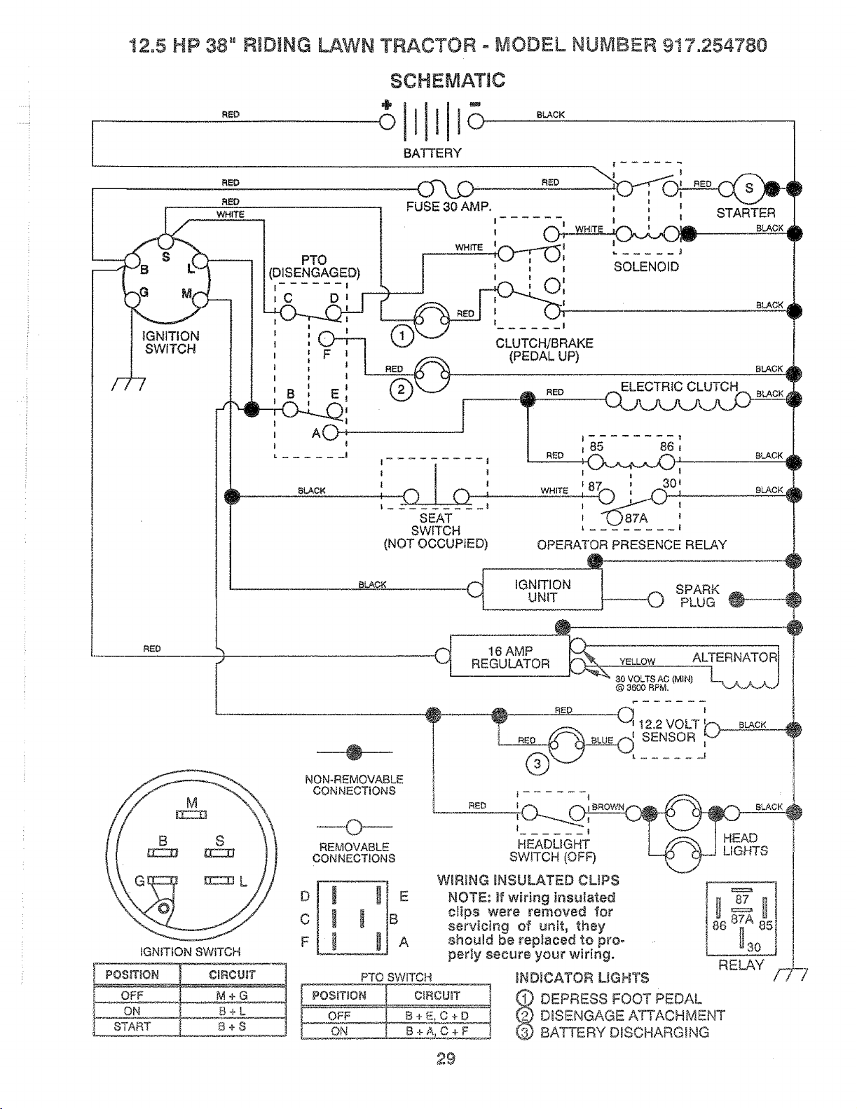
.... i,
12.5 HP 38" RIDING LAWN TRACTOR = MODEL NUMBER 917.254780
SCHEMATIC
•tlM°
_°° ollio °_CK
BATTERY
RED RED
f
RE0
!
_GNtTtON SWITCH
@LACK
_1
I
SEAT
SWITCH
(NOT OCCUPIED)
BLACK
f 87 ' 301
WHITE __,._ ;
[ UaTA :
@
NON-REMOVABLE
CONNECTIONS
O
REMOVABLE
CONNECTIONS
o t _IE
c _ _ B
F _ _A
PTO SWITCH
ON
BLACK
OPERATOR PRESENCE RELAY
IGNITION !@ SPARK
UN{T PLUG _P'_--_
{_ 16 AMP ._
REGULATOR YELLOW ALTERNATOR
]
30 VOLTS AC.(M1N) _L_ _ j_,_
@ 3600 RPM,
"J1t 2,2 VOLT _"';
SENSOR;'>
......... t
BLACK
RED
| _
...... HEAD
SWITCH (OFF) L_ _,9...ULtL_.t b
V
W_RIa G _N SULAT_C) CLiP S
I ,1
ctips were removed for _= HI
servicing of unit, they _ 85
should be replaced to pro= U
perly secure your wiring.
RELAY
_ND_CATOR UGHTS
DEPRESS FOOT PEDAL
DISENGAGE ATTACHMENT
BATTERY DISCHARGING
OIROUBT 1
29
i
I
i
P
i,
}
4}
!
}
!-i-Z
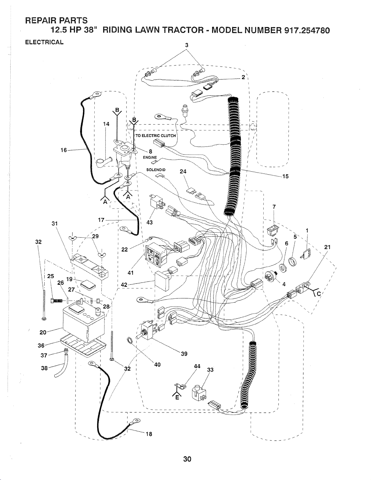
.... i
REPAIR PARTS
12.,5 HP 38" RIDING LAWN TRACTOR - MODEL NUMBER 91'7.254780
ELECTRICAL
14
22
8
43
41
42
\
\
7
[
/
\ i
\
T ....
E
E
30
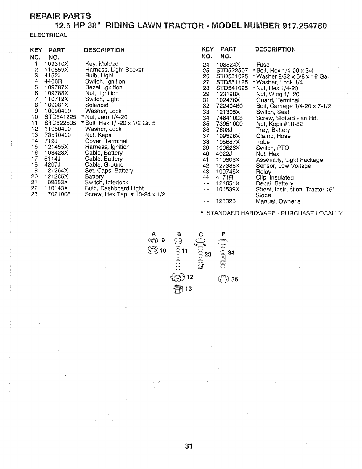
.....!
...... i
REPAIR PARTS
12,5 HP 38"
ELECTRICAL
RiDiNG
LAWN TRACTOR = MODEL NUMBER 917,254780
KEY PART
NO. NO.
I 109310X
2 110859X
3 4152J
4 4406R
5 109787X
6 109788X
7 110712X
8 10908tX
9 10090400
10 STD541225
11 STD522505
12 11050400
13 73510400
14 719J
I5 121455X
16 108423X
I7 5114J
18 4207J
19 I2t264X
20 I2t265X
2! t09553X
22 1t0143X
23 17021008
DESCRIPTION
Key, Molded
Harness, Light Socket
Bulb, Light
Switch, Ignition
Bezel; Ignition
Nut, Ignition
Switch, Ught
Solenoid
Washer, Lock
Nut, Jam 1/4_20
Bolt, Hex 1/-20 x 1/2 Gr. 5
Washer, Lock
Nut, Keps
Cover, Terminal
Harness, Ignition
Cable, Battery
Cable, Battery
Cable, Ground
Set, Caps, Battery
Battery
Switch, Interlock
Bulb, Dashboard Light
Screw, Hex Tap. # 10-24 x t/2
KEY PART DESCRIPTION
NO. NO.
24 108824X Fuse
25 STD522507 *Bolt, Hex !/4-20 x 3/4
26 STD551025 * Washer 9/32 x 5/8 x t6 Ga.
27 STD551125 *Washer, Lock !/4
28 STD541025 *Nut, Hex 1/4-20
29 123198X Nut, Wing 1/-20
31 102476X Guard, Terminal
32 72240460 Bolt, Carriage 1/4-20 x 7-1/2
33 121305X Switch, Seat
34 7464t008 Screw, Slotted Pan Hd.
35 73951000 Nut, Keps #10-32
36 7603J Tray, Battery
37 109596X Clamp, Hose
38 105687X Tube
39 109626X Switch, PTO
40 4022J Nut, Hex
41 110808X Assembly, Light Package
42 127385X Sensor, LowVoltage
43 I09748X Relay
44 4171R Clip, Insulated
-- 121651X Decal, Battery
- - 101539X Sheet, Instruction, Tractor 15°
Slope
-- 128326 Manual, Owner's
* STANDARD HARDWARE - PURCHASE LOCALLY
A
_9
@io
B C
35
i:
31
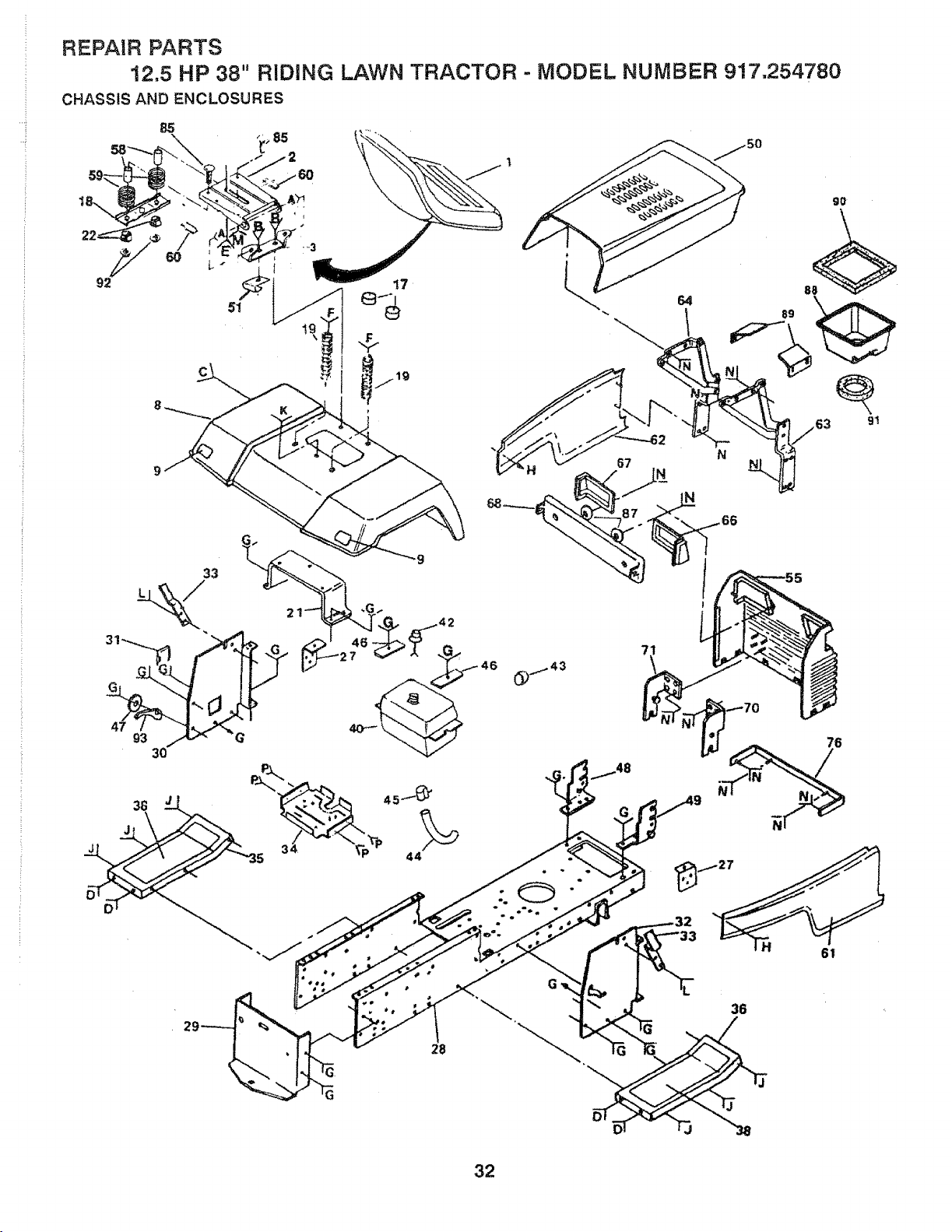
REPAIR PARTS
!2,5 HP 38" RIDING LAWN TRACTOR .. MODEL NUMBER 917,254780
CHASSIS AND ENCLOSURES
48
76
36
61
28
32
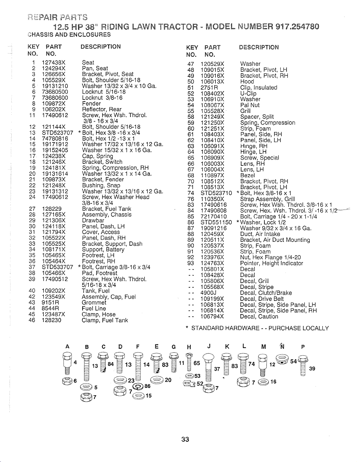
.... !
;'::PA R tS
12,5 HP 38" RID1NG
0HASSIS AND ENCLOSURES
LAWN TRACTOR o MODEL NUMBER 9!7,254780
KEY PART DESCRIPTION
NO. NO.
1 127438X Seat
2 124294X Pan, Seat
3 126656X Bracket, Pivot, Seat
4 105529X Bolt, Shoulder 5/t6-t8
5 19131210 Washer 13/32 x 3/4 x 10 Ca.
6 73680500 Locknut 5/16-18
7 73680600 Locknut 3/8-16
8 109872X Fender
9 106202X Reflector, Rear
ti 17490612 Screw, Hex Wsh. Thdrol.
3/8 - 16 x 3/4
12 t21144X Bolt, Shoulder5/16-18
13 STD523707 * Bolt, Hex 3/8 -16 x 3/4
14 74780816 Bolt, Hex t/2 -t3 x 1
t5 19171912 Washer 17/32 x t3/I6 x 12 Ca.
16 19152405 Washer 15/32 x 1 x 16 Ca.
17 124238X Cap, Spring
18 t2t246X Bracket, Switch
19 t2418IX Spring, Compression, RH
20 19131614 Washer13i32x 1 x 14Ca.
21 I09873X Bracket, Fender
22 12t248X Bushing, Snap
23 19131312 Washer I3/32 x 13/16 x 12 Ca.
24 I74906t2 Screw, Nex Washer Head
3/8-16 x 3/4
27 128229 Bracket, Fuel Tank
28 I27165X Assembly, Chassis
29 I21306X Drawbar
30 124118X Panel, Dash, LH
31 121794X Cover, Access
32 105522X Panel, Dash, RH
33 105525X Bracket, Support, Dash
34 10817tX Support, Battery
35 105465X Footrest, LH
36 105464X Footrest, RH
37 STD533707 * Bolt, Carriage 3/8-16 x 3/4
38 I05466X Pad, Footrest.
39 t74905!2 Screw, Hex Wsh. Thdrol.
5/16-18 x 3/4
40 109202X Tank, Fuel
42 123549X Assembly, Cap, Fuel
43 9151R Grommet
44 8544R Fuel Line
45 123487X Clamp, Hose
46 128230 Clamp, Fuel Tank
KEY PART DESCRIPTION
NO. NO.
47 120529X
48 109015X
49 109016X
50 106013X
51 2751R
52 108402X
53 106910X
54 108067X
55 105528X
58 I21249X
59 !21250X
60 t2!251X
6I 108403X
62 I08410X
63 t06091X
64 106090X
65 I06909X
66 106003X
67 I06004X
68 tt0897X
70 1085t2X
7t I08513X
74 STD523710
76 t10350X
83 17490616
84 17490608
85 72170410
86 STD551150
87 19091216
88 120459X
89 120511X
90 120537X
9I 120536X
92 123976X
93 t24763X
-- t0580IX
-- t08428X
_- I05806X
-- t05568X
-- 4900J
- - 109199X
- - 1068t3X
- - 1068t4X
-- 106794X
* STANDARD
Washer
Bracket, Pivot, LH
Bracket, Pivot, RH
Hood
Clip, Insulated
U-Clip
Washer
Pal Nut
Grill
Spacer, Split
Spring, Compression
Strip, Foam
Panel, Side, RH
Panel, Side, LH
Hinge, RH
Hinge, LH
Screw, Special
Lens, RH
Lens, LH
Bezel
Bracket, Pivot, RH
Bracket, Pivot, LH
* Bolt, Hex 3/8-16 x 1
Strap Assembly, Grill
Screw, Hex Wsh. Thdrot. 3/8-16 x 1
Screw, Hex. Wsh. Thdrol. 3/-16 x 1/_ _
Bolt, Carriage t/4 - 20 x 1-1/4
*Washer, Lock t/2
Washer 9/32 x 3/4 x t6 Ca.
Duct, Air Intake
Bracket, Air Duct Mounting
Strip, Foam
Strip, Foam
Nut, Hex Flange t/4-20
Pointer, Height Indicator
Decal
Decal
Decal, Grill
Decal, Stripe
Decal, Clutch/Brake
Decal, Drive Belt
Decal, Stripe, Side Panel, LH
Decal, Stripe, Side Panel, RH
Decal, Caution
HARDWARE - o PURCHASE LOCALLY
A B C D F E G H J K L M '_ P
39
33
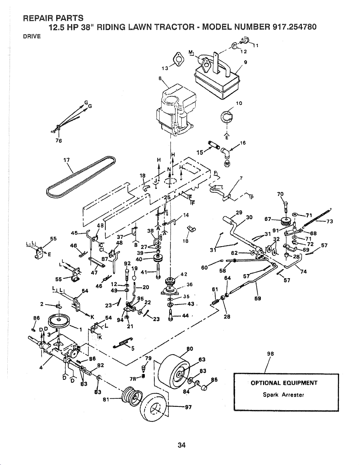
REPAIR PARTS
12.5 HP 38" RiDiNG LAWN TRACTOR., MODEL NUMBER 917,254780
DRIVE
12
9
18
34
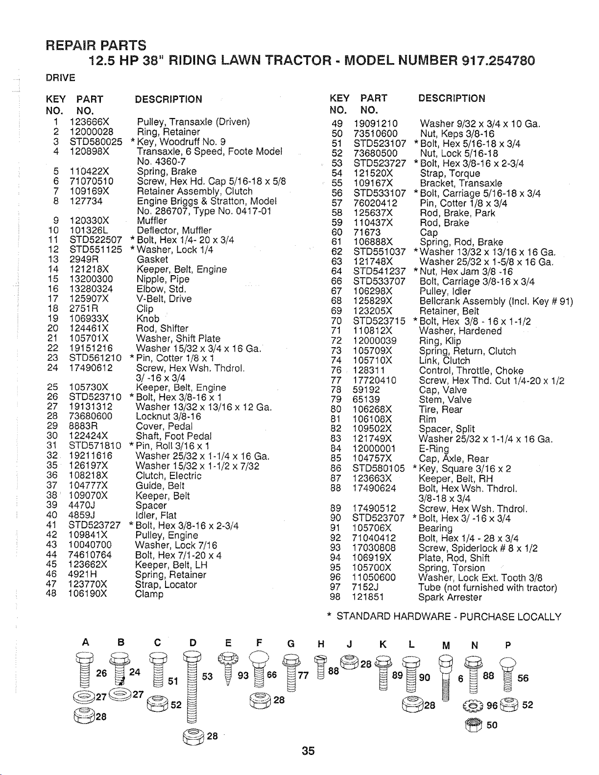
REPAIR PARTS
12.5 HP 38"
DRIVE
RIDING LAWN TRACTOR - MODEL NUMBER 917.254780
KEY PART
NO. NO.
1 123666X
2 12000028
3 STD580025
4 120898X
5 110422X
6 71070510
7 109169X
8 127734
9 120330X
10 101326L
I1 STD522507
12 STD551125
13 2949R
t4 t21218X
15 13200300
16 13280324
17 125907X
18 275tR
19 106933X
2O !24461X
21 105701X
22 19151216
23 STD561210
24 17490612
25 105730X
26 STD523710
27 19131312
28 73680600
29 8883R
30 122424X
3! STD571810
32 19211616
35 126197X
36 108218X
37 104777X
38 _ I09070X
39 4470J
40 4859J
41 STD523727
42 109841X
43 10040700
44 74610764
45 123662X
46 492tH
47 123770X
48 t06190X
DESCRIPTION
Pulley, Transaxle (Driven)
Ring, Retainer
* Key, Woodruff No. 9
Transaxle, 6 Speed, Foote Model
No. 4360-7
Spring, Brake
Screw, Hex Hd. Cap 5/16-18 x 5/8
Retainer Assembly, Clutch
Engine Briggs & Stratton, Model
No. 286707, Type No. 04t 7-01
Muffler
Deflector, Muffler
* Bolt, Hex 1/4- 20 x 3/4
* Washer, Lock 1/4
Gasket
Keeper, Belt, Engine
Nipple, Pipe
Elbow, Std.
V-Belt, Drive
Clip
Knob
Rod, Shifter
Washer, Shift Plate
Washer 15/32 x 3/4 x 16 Ga.
* Pin, Cotter 1/8 x 1
Screw, Hex Wsh. Thdrol.
3/-16 x 3/4
Keeper, Belt, Engine
*Bolt, Hex 3/8-t6 x 1
Washer 13/32 x 13/16 x t2 Ga.
Locknut 3/8-16
Cover, Pedal
Shaft, Foot Pedal
* Pin, Roll 3/16 x 1
Washer 25/32 x 1-1/4 x 16 Ga.
Washer t5/32 x 1-1/2 x 7/32
Clutch, Electric
Guide, Belt
Keeper, Belt
Spacer
Idler, Flat
* Bolt, Hex 3/8-16 x 2-3/4
Pulley, Engine
Washer, Lock 7/16
Bolt, Hex 7/1-20 x 4
Keeper, Belt, LH
Spring, Retainer
Strap, Locator
Clamp
KEY PART
NO. NO,
49 19091210
50 73510600
51 STD523107
52 73680500
53 STD523727
54 121520X
55 t09!67X
56 STD533107
57 76020412
58 125637X
59 110437X
60 71673
61 106888X
62 STD551037
63 12t748X
64 STD541237
66 STD533707
67 106298X
68 125829X
69 123205X
70 STD523715
71 1108t2X
72 12000039
73 105709X
74 105710X
76, 128311
77 17720410
78 59192
79 65139
80 106268X
81 106108X
82 109502X
83 121749X
84 12000001
85 t04757X
86 STD580105
87 I23663X
88 17490624
89 17490512
90 STD523707
91 105706X
92 71040412
93 17030808
94 106919X
95 105700X
96 11050600
97 7152J
98 121851
DESCRIPTION
Washer 9/32 x 3/4 x 10 Ga.
Nut, Keps 3/8-16
* Bolt, Hex 5/16-18 x 3/4
Nut, Lock 5/16-18
* Bolt, Hex 3/8-16 x 2-3/4
Strap, Torque
Bracket, Transaxle
* Bolt, Carriage 5/16-18 x 3/4
Pin, Cotter 1/8 x 3/4
Rod, Brake, Park
Rod, Brake
Cap
Spring, Rod, Brake
*Washer 13/32 x 13/16 x 16 Ga.
Washer 25/32 x 1-5/8 x 16 Ga.
*Nut, Hex Jam 3/8 -16
Bolt, Carriage 3/8.t6 x 3/4
Pulley, Idler
Bellcrank Assembly (inc!. Key # 91)
Retainer, Belt
* Bolt, Hex 3/8 - t6 x 1-!/2
Washer, Hardened
Ring, Klip
Spring, Return, Clutch
Link, Clutch
Control, Throttle, Choke
Screw, Hex Thd. Cut 1/4-20 x 1/2
Cap, Valve
Stem, Valve
Tire, Rear
Rim
Spacer, Split
Washer 25/32 x 1-1/4 x 16 Ga.
E-Ring
Cap, Axle, Rear
* Key, Square 3/t6 x 2
Keeper, Belt, RH
Bolt, Hex Wsh. Thdrol.
3/8-18 x 3/4
Screw, Hex Wsh. Thdrol.
* Bolt, Hex 3/-16 x 3/4
Bearing
Bolt, Hex t/4 - 28 x 3/4
Screw, Spidertock # 8 x 1/2
Plate, Rod, Shift
Spring, Torsion
Washer, Lock Ext. Tooth 3/8
Tube (not furnished with tractor)
Spark Arrester
* STANDARD HARDWARE - PURCHASE LOCALLY
A B C D
28 -
E F G H J K L
@28
35
M N P
6 88 '56
@ 96@
so
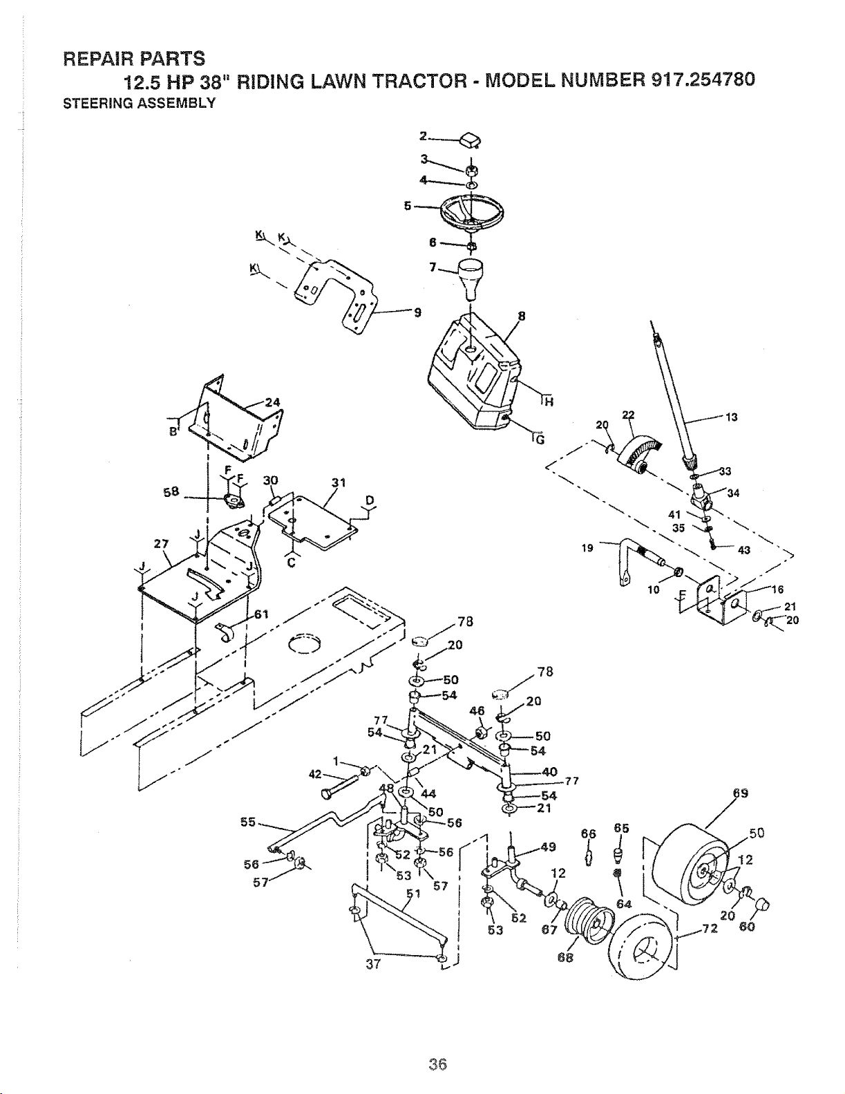
REPAIR PARTS
12.5 HP 38" RIDING LAWN TRACTOR - MODEL NUMBER 917.254780
STEERING ASSEMBLY
27
¢
19
36
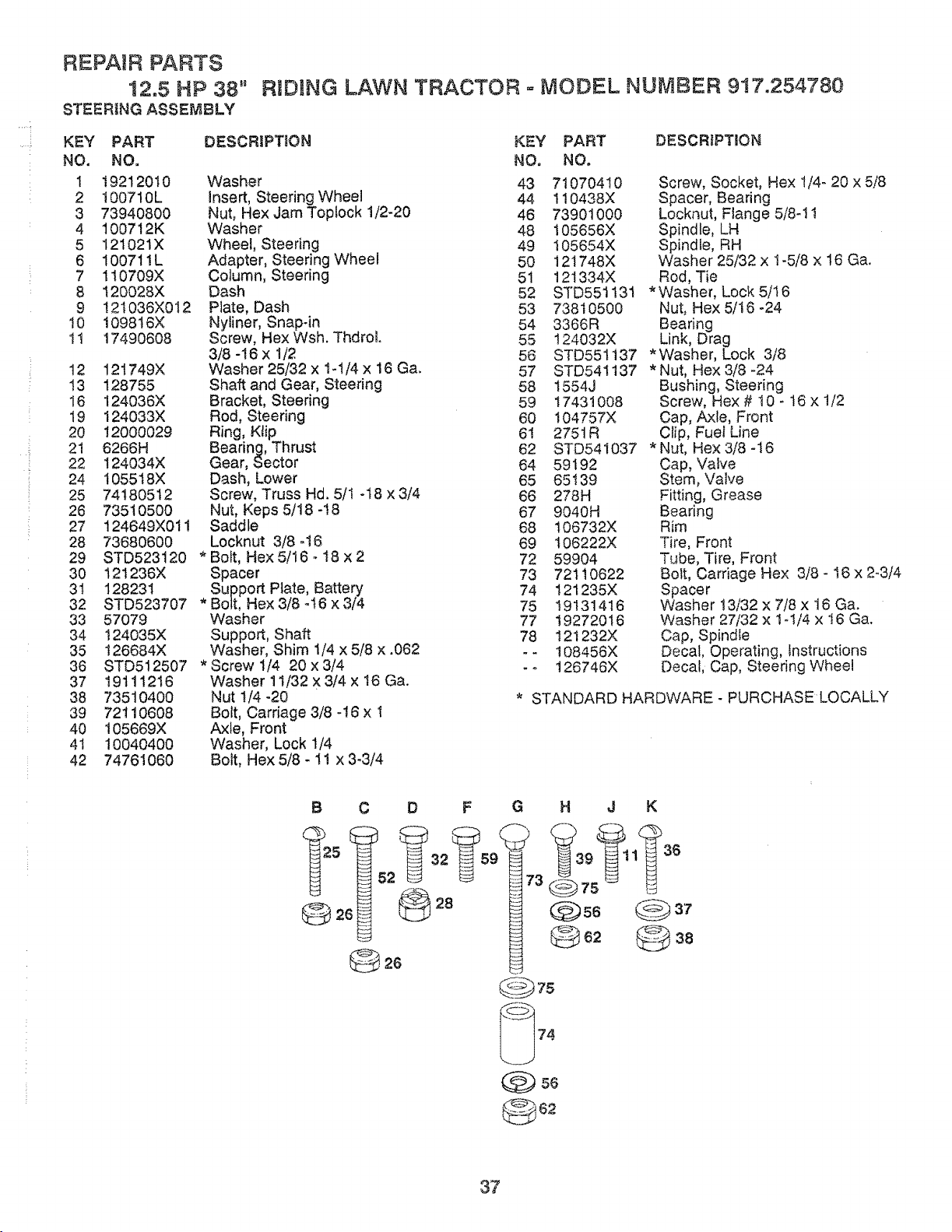
REPAIR PARTS
12.5 HP 38"
STEERING ASSEMBLY
RIDING LAWN TRACTOR ° MODEL NUMBER 917.254780
KEY PART
NO. NO.
t 19212010
2 100710L
3 73940800
4 100712K
5 121021X
6 100711L
7 !10709X
8 120028X
9 121036X012
10 109816X
11 17490608
t2 12t749X
t3 128755
I6 124036X
19 124033X
20 12000029
2t 6266H
22 124034X
24 1055t8X
25 74180512
26 73510500
27 124649X011
28 73680600
29 STD523120
30 I21236X
31 128231
32 STD523707
33 57079
34 I24035X
35 126684X
38 STD512507
37 19111216
38 73510400
39 72110608
40 105669X
41 10040400
42 74761060
DESCRtPT!ON KEY PART
NO, NO.
Washer 43 71070410
Insert, Steering Wheel 44 110438X
Nut, Hex Jam Toplock 1/2-20 46 73901000
Washer 48 105656X
Wheel, Steering 49 I05654X
Adapter, Steering Wheel 50 121748X
Column, Steering 5t 121334X
Dash 52 STD551131
Plate, Dash 53 73810500
Nyliner, Snap-in 54 3366R
Screw, Hex Wsh. Thdrol. 55 124032X
3/8-16 x 1/2 56 STD551137
Washer25/32xl.1/4x16Ga. 57 STD54!137
Shaft and Gear, Steering 58 1554J
Bracket, Steering 59 17431008
Rod, Steering 60 104757X
Ring, Ktip 6! 275tR
Bearing, Thrust 62 STD541037
Gear, Sector 64 59192
Dash, Lower 65 65t39
Screw, Truss Hd. 5/1 ot8 x 3/4 66 278H
Nut, Keps 5/18-!8 67 9040H
Saddle 68 106732X
Locknut 3/8 o16 69 106222X
* Bolt, Hex 5/16 _I8 x 2 72 59904
Spacer 73 72110622
Support Plate, Battery 74 121235X
*Bett, Hex3/8q6x3i4 75 19131416
Washer 77 19272016
Support, Shaft 78 121232X
Washer, Shim 1/4 x 5/8 x .062 - - 108456X
* Screw 1/4 20 x 3/4 - o 126746X
Washer 11/32 X 3/4 x 16 Ga.
Nut t/4 -20 *
Bolt, Carriage 3/8.16 x 1
Axle, Front
Washer, Lock 1/4
Bolt, Hex 5/8 - 1! x 3-3/4
DESCRIPTmON
Screw, Socket, Hex 1/4- 20 x 5/8
Spacer, Bearing
Locknut, Flange 5/8-11
Spindle, LH
Spindle, RH
Washer 25/32 x t-5/8 x 16 Ga.
Rod, Tie
* Washer, Lock 5/16
Nut, Hex 5/16 -24
Bearing
Link, Drag
*Washer, Lock 3/8
* Nut, Hex 3/8 -24
Bushing, Steering
Screw, Hex# 10- t6x !/2
Cap, Axle, Front
Clip, Fuel Line
* Nut, Hex 3/8 -16
Cap, Valve
Stem, Valve
Fitting, Grease
Bearing
Rim
Tire, Front
Tube, Tire, Front
Bolt, Carriage Hex 3/8 - 16 x 2-3/4
Spacer
Washer !3/32 x 7/8 x 16 Ga.
Washer 27/32 x 1-t/4 x 16 Ga.
Cap, Spindle
Decal, Operating, Instructions
Decal, Cap, Steering Wheel
STANDARD HARDWARE - PURCHASE LOCALLY
B C D F G H J K
6! 32 59_
_@37
37
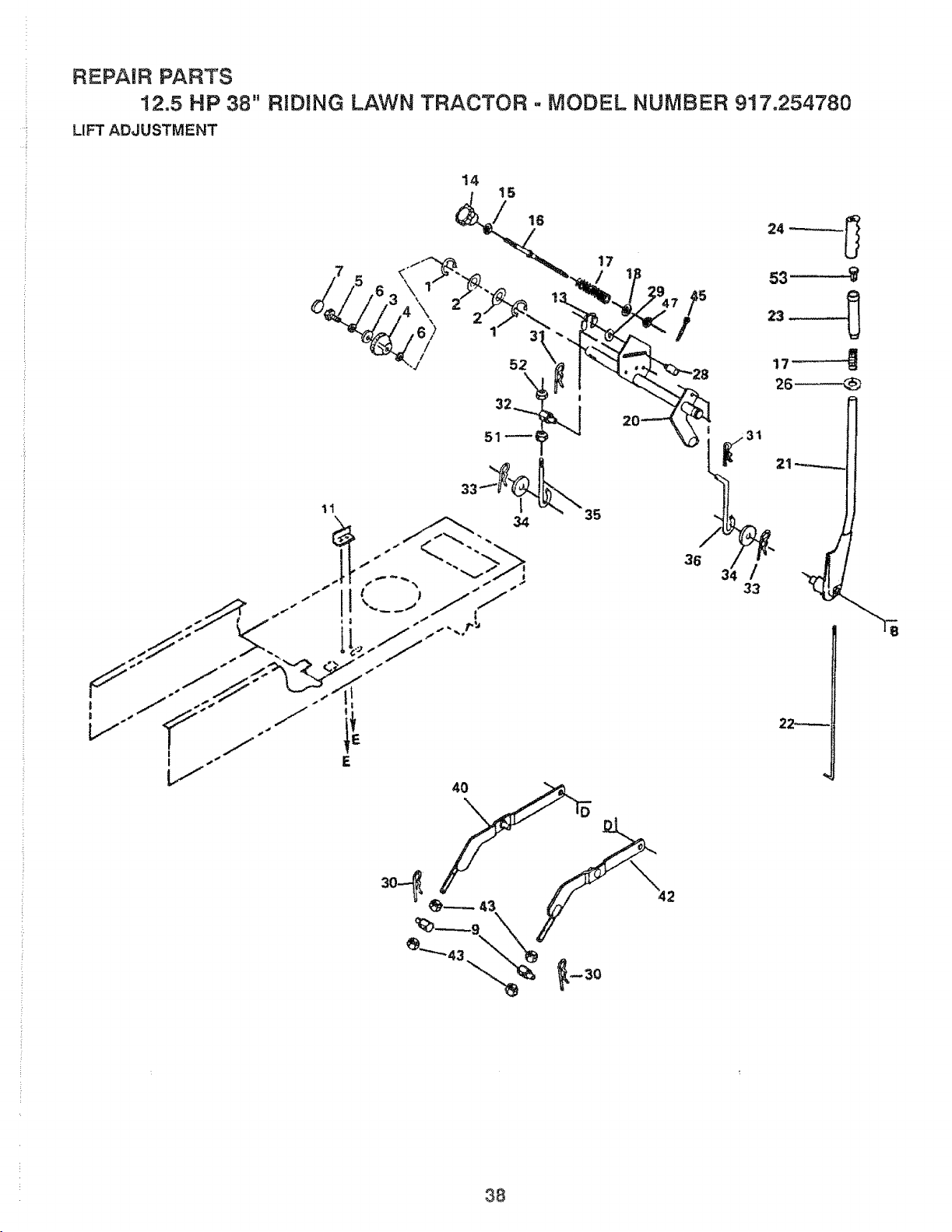
REPAIR PARTS
12.5 HP 38" RiDiNG LAWN TRACTOR ° MODEL NUMBER 917.254780
LIFT ADJUSTMENT
14
15
/ is
11
1:
34 35
17
42
36
/
33
s3 :'_
22_
38
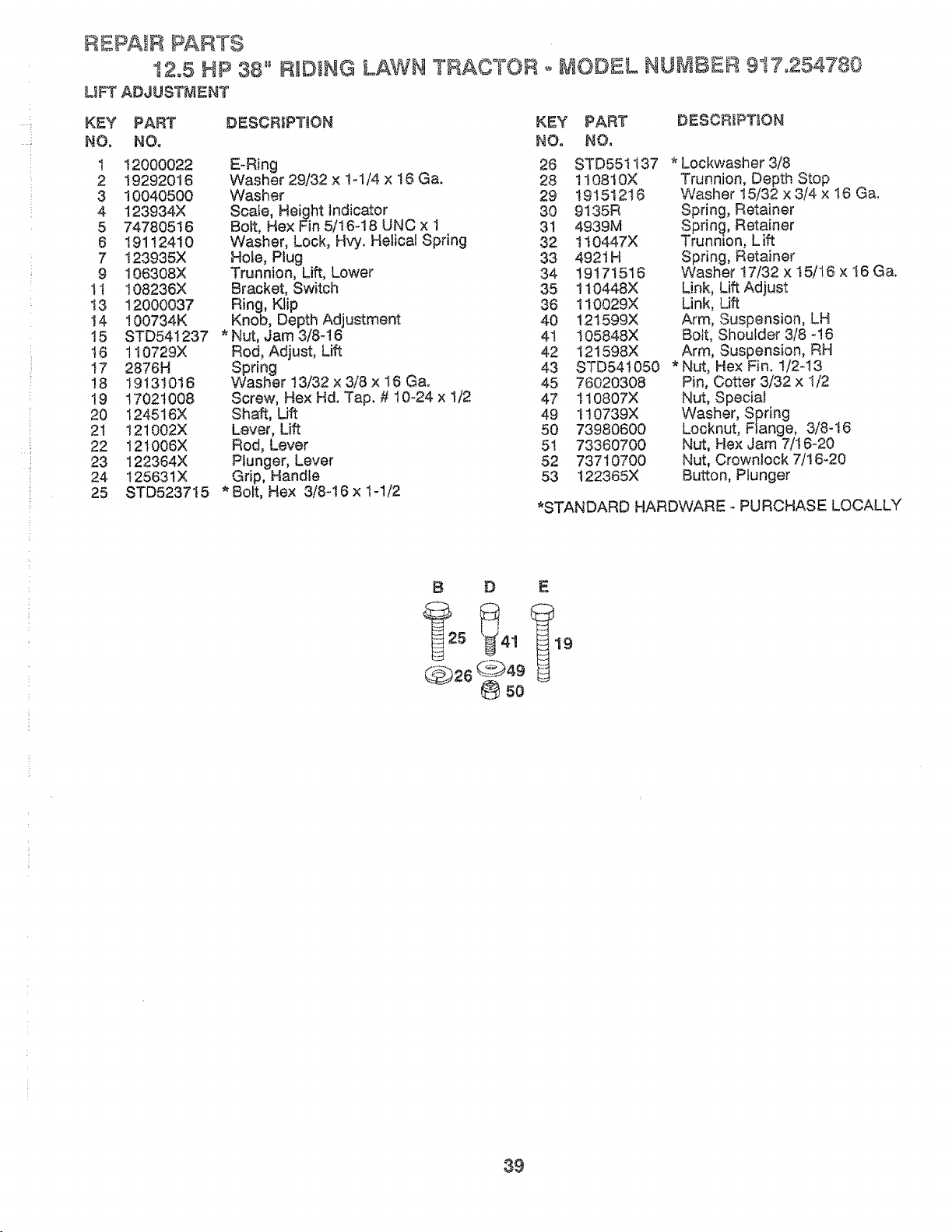
!
REPAIR PARTS
12.5 HP 38" RIIDING LAWN TRACTOR o MODEL NU_v_BE£ 917.254780
LIFT ADJUSTMENT
KEY PART DESCRiPTiON KEY PART
NO. NO. NO. NO.
1 t2000022 E-Ring 26 STD551t37
2 19292016 Washer 29/32 x t-t/4 x 16 Ga. 28 110810X
3 10040500 Washer 29 19t512t6
4 123934X Scale, Height Indicator 30 9135R
5 74780516 Bolt, Hex Fin 5/16-18 UNC x 1 31 4939M
8 191!2410 Washer, Lock, Hvy. Helical Spring 32 110447X
7 123935X Hole, Plug 33 4921H
9 106308X Trunnion, Lift, Lower 34 19!71516
1t t08236X Bracket, Switch 35 1t0448X
13 12000037 Ring, Ktip 36 1I0029X
14 100734K Knob, Depth Adjustment 40 121599X
15 STD541237 *Nut, Jam 3/8-!6 4! 105848X
16 t10729X Rod, Adjust, Lift 42 121598X
t7 2876H Spring 43 STD541050
!8 19131016 Washer I3/32x3/8 x 16 Ga° 45 76020308
19 17021008 Screw, Hex Hd. Tap. # 10-24 x 1/2 47 110807X
20 124516X Shaft, Lift 49 1t0739X
21 121002X Lever, Lift 50 73980600
22 t2t006X Rod, Lever 51 73360700
23 t22364X Plunger, Lever 52 73710700
24 t25631X Grip, Handle 53 122365X
25 STD523715 * Bolt, Hex 3/8-16 x t-1/2
DESCRiPTiON
* Lockwasher 3/8
Trunnion, Depth Stop
Washer 15/32 x 3/4 x 16 Ga.
Spring, Retainer
Spring., Retainer
TrunnLon, Lift
Spring, Retainer
Washer !7/32 x 15/16 x I6 Ga.
Link, Lift Adjust
Link, Lift
Arm, Suspension, LH
Bott, Shoulder 3/8 o!6
Arm, Suspension, RH
*Nut, Hex Fin. 1/2-t3
Pin, Cotter 3/32 x I/2
Nut, Speciai
Washer, Spring
Locknut, Flange, 3/8-16
Nut, Hex Jam 7/!6-20
Nut, Crowniock 7/16-20
Button, Plunger
*STANDARD HARDWARE _ PURCHASE LOCALLY
B b E
d_b26¢2+)49
39
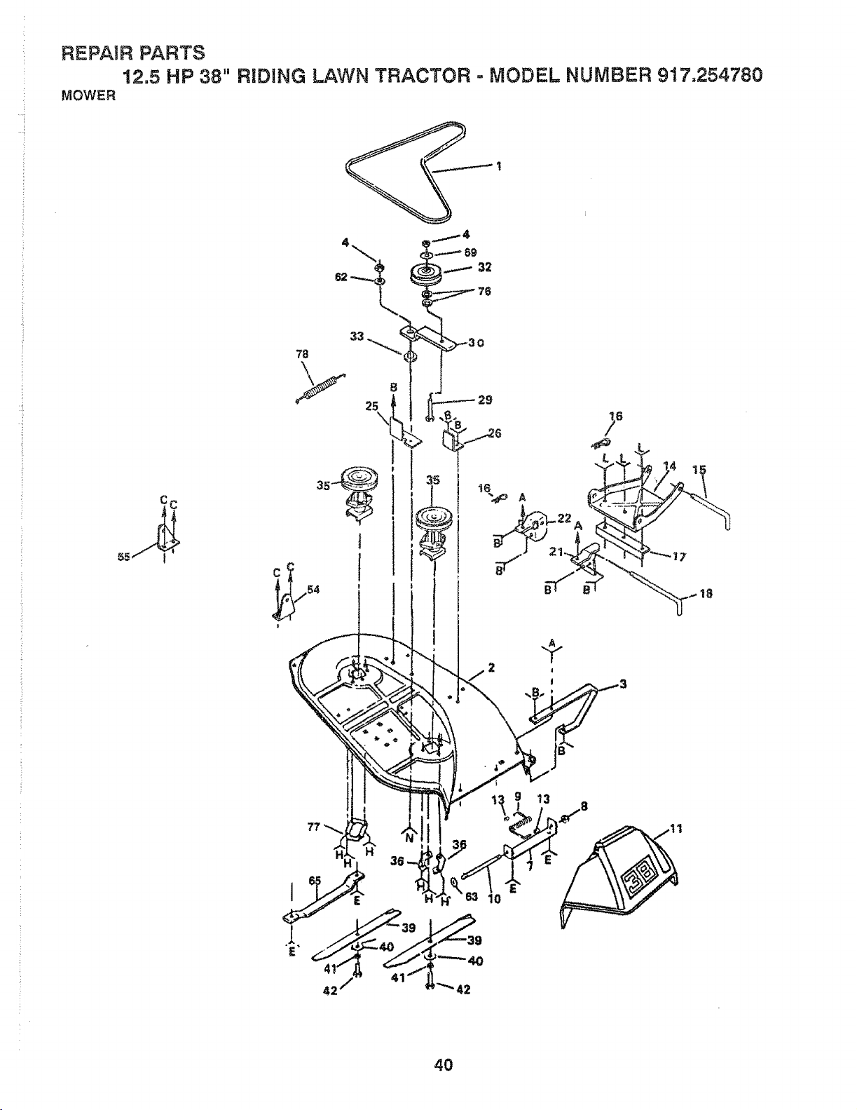
H,
H.
REPAIR PARTS
12,5 HP 38" RIDING LAWN TRACTOR = MODEL NUMBER 917,254780
MOWER
C C
4O
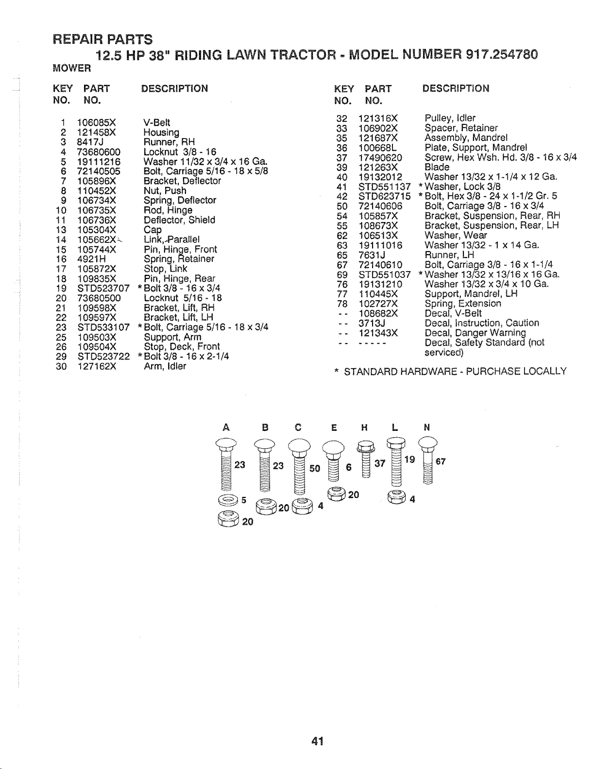
.... !
..... i
REPAIR PARTS
!2,5 HP 38"
MOWER
RIDING LAWN TRACTOR - MODEL NUMBER 917.254780
KEY PART
NO, NO.
DESCRIPTION KEY PART DESCRIPTION
NO. NO.
1 !06085X
2 !21458X
3 84!7J
4 73680600
5 19111216
6 72140505
7 105896X
8 110452X
9 106734X
10 106735X
11 106736X
13 105304X
!4 105662X_.
15 105744X
16 4921H
17 105872X
18 109835X
t9 STD523707
20 73680500
21 109598X
22 !09597X
23 STD533107
25 109503X
26 t09504X
29 STD523722
30 127162X
V-Belt
Housing
Runner, RH
Locknut 3/8 * t6
Washer 11/32 x 3/4 x 16 Ga.
Bolt, Carriage 5/16 - t8 x 5/8
Bracket, Deflector
Nut, Push
Spring, Deflector
Rod, Hinge
Deflector, Shield
Cap
Link,.Parallel
Pin, Hinge, Front
Spring, Retainer
Stop, Link
Pin, Hinge, Rear
• Bolt 3/8 - 16 x 3/4
Locknut 5/t6 - 18
Bracket, Lift, RH
Bracket, Lift, LH
• Bolt, Carriage 5/! 6 - 18 x 3/4
Support, Arm
Stop, Deck, Front
• Bolt 3/8 - 16 x 2-1/4
Arm, Idler
32 121316X
33 106902X
35 121687X
36 100668L
37 17490620
39 121263X
40 19132012
41 STD551137
42 STD623715
50 72140606
54 I05857X
55 108673X
62 106513X
63 19111016
65 7631J
67 72140610
69 STD551037
76 19131210
77 !10445X
78 102727X
-- 108682X
-- 3713J
o- 121343X
Pulley, idler
Spacer, Retainer
Assembly, Mandrel
Plate, Support, Mandrel
Screw, Hex Wsh. Hd. 3/8 - 16 x 3/4
Blade
Washer 13/32 x 1-t/4 x 12 Ga.
* Washer, Lock 3/8
* Bolt, Hex 3/8 - 24 x 1q/2 Gr. 5
Bolt, Carriage 3/8 - 16 x 3/4
Bracket, Suspension, Rear, RH
Bracket, Suspension, Rear, LH
Washer, Wear
Washer 13/32 - ! x 14 Ga.
Runner, LH
Bolt, Carriage 3/8 - 16 x 1-1/4
* Washer 13/32 x 13/16 x 16 Ga.
Washer t3/32 x 3/4 x 10 Ga.
Support, Mandrel, LH
Spring, Extension
Decal, V-Belt
Decal, Instruction, Caution
Decal, Danger Warning
Decal, Safety Standard (not
serviced)
* STANDARD HARDWARE - PURCHASE LOCALLY
A B C L N
@4
41
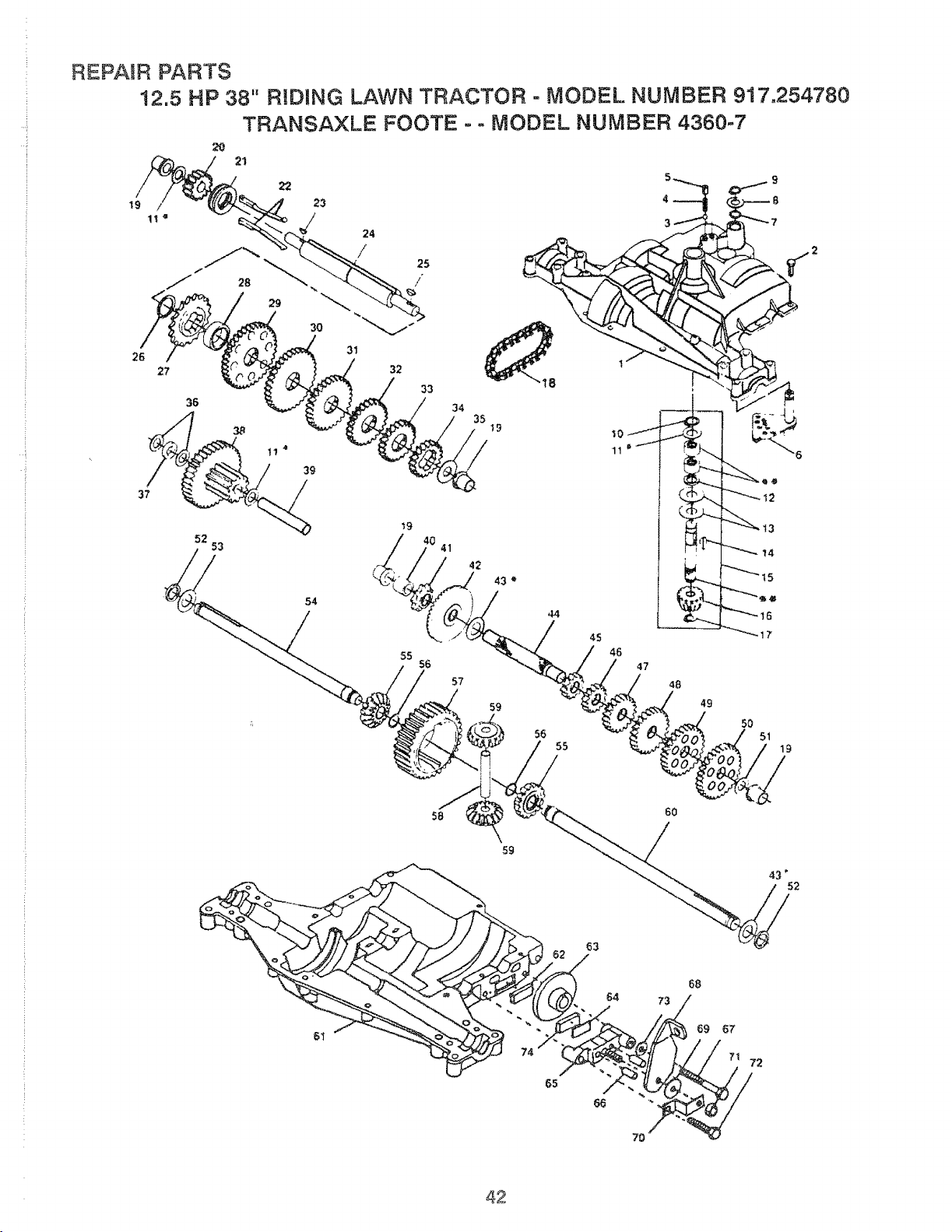
]
!
REPAIR PARTS
t2.5 HP 38" RIDING LAWN TRACTOR - MODEL NUMBER 917,254780
TRANSAXLE FOOTE - - MODEL NUMBER 4360-7
20
2t
19 f
25
/
52 53
54
_o
41
55
56
57
46
47
49
56
55
61
58
6O
59
64 73/8
42
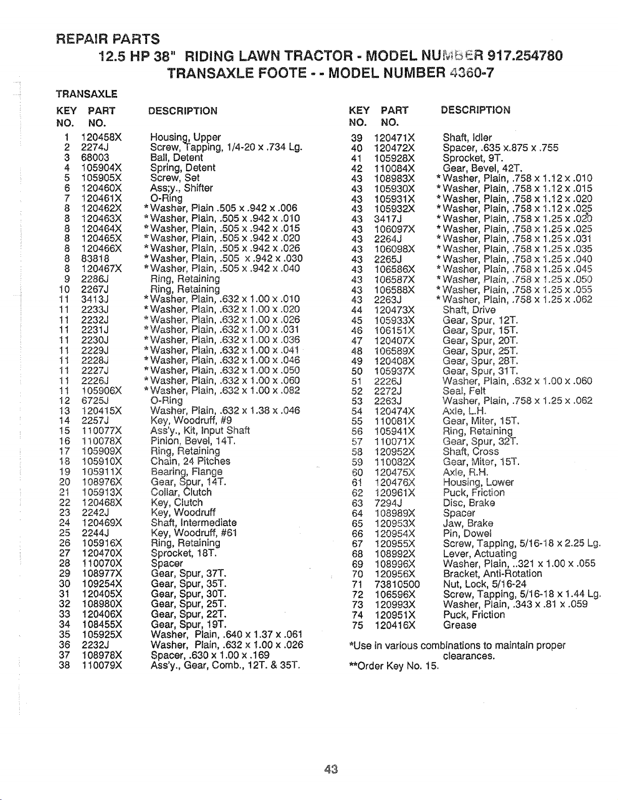
REPAIR PARTS
12.5 HP 38" RIDING LAWN TRACTOR - MODEL NUMbeR 917.254780
TRANSAXLE FOOTE -.- MODEL NUMBER 4360=7
TRANSAXLE
KEY PART
NO. NO.
1 120458X
2 2274J
3 68003
4 105904X
5 105905X
6 120460X
7 !2046tX
8 120462X
8 120463X
8 120464X
8 120465X
8 !20466X
8 83818
8 t20467X
9 2286J
t0 2267J
It 3413J
I1 2233J
11 2232J
11 2231J
tl 2230J
!1 2229J
11 2228J
tl 2227J
1t 2226J
tt 105906X
12 6725J
t3 I204t5X
14 2257J
t5 110077X
16 110078X
17 105909X
t8 t05910X
!9 10591IX
20 108976X
21 105913X
22 120468X
23 2242J
24 120469X
25 2244J
26 105916X
27 120470X
28 110070X
29 !08977X
30 109254X
3t 120405X
32 108980X
33 120406X
34 108455X
35 !05925X
36 2232J
37 108978X
38 110079X
DESCRIPTION KEY PART DESCRIPTION
NO. NO.
*Washer
*Washer
*Washer
*Washer
*Washer
*Washer
*Washer
O-Ring
Housing, Upper
Screw, Tapping, 1/4-20 x .734 Lg.
Ball, Detent
Spring, Detent
Screw, Set
Ass;y., Shifter
O-Ring
* Washer, Plain .505 x .942 x .006
* Washer, Plain, .505 x.942 x.010
* Washer, Plain, .505 x .942 x .015
* Washer, PLain, .505 x .942 x .020
* Washer, Plain, .505 x .942 x .026
* Washer, Plain, ,505 x ,942 x .030
*Washer, Plain, °505 x .942 x .040
Ring, Retaining
Ring, Retaining
* Washer, Plain, .632 x 1.00 x .010
*Washer, Plain, .632 x t.00 x .020
*Washer Plain, .632 x 1.00 x .026
Plain, .632 x 1.00 x .031
Plain, .632 x 1.00 x .036
Plain, .632 x 1.00 x .04I
Plain, .632 x 1.00 × .046
Plain, .632 x 1o00 x .050
Plain, .632 x ! .00 x .060
Plain, .632 x ! .00 x °082
Washer, Plain, .632 x !.38 x .046
Key, Woodruff, #9
Ass'y., Kit, Input Shaft
Pinion, Bevel, 14T.
Ring, Retaining
Chain, 24 Pitches
Bearing, Flange
Gear, Spur, !4T.
ColJar, Clutch
Key, Clutch
Key, Woodruff
Shaft, Intermediate
Key, Woodruff, #6t
Ring, Retaining
Sprocket, 18T.
Spacer
Gear, Spur, 37T.
Gear, Spur, 35T.
Gear, Spur, 30T.
Gear, Spur, 25T.
Gear, Spur, 22T.
Gear, Spur, t9T.
Washer, Plain, .640 x 1.37 x .061
Washer, Plain, .632 x 1.00 x .026
Spacer, .630 x 1.00 x .189
Ass'y., Gear, Comb., 12T. & 35T.
39 120471X
40 120472X
41 105928X
42 110084X
43 108983X
43 105930X
43 105931X
43 t05932X
43 3417J
43 106097X
43 2264J
43 106098X
43 2265J
43 106586X
43 106587X
43 106588X
43 2263J
44 120473X
45 !05933X
46 t0615tX
47 120407X
48 106589X
49 120408X
50 105937X
51 2226J
52 2272J
53 2263J
54 t20474X
55 1t0081X
56 105941X
57 1t0071X
58 120952X
59 t10082X
60 120475X
6t 120476X
62 t20961X
63 7294J
64 108989X
65 120953X
66 120954X
67 120955X
68 108992X
69 108996X
70 120956X
71 73810500
72 106596X
73 120993X
74 120951X
75 120416)(
*Washer
*Washer
*Washer
*Washer
* Washer
* Washer
* Washer
* Washer
* Washer
*Washer
*Washer
*Washer
*Washer
Shaft, Idler
Spacer, .635 x.875 x .755
Sprocket, 9T.
Gear, Bevel, 42T.
Plain, .758 x 1.12 x .010
Plain, .758 x !.12 x .0t5
Plain, .758 x 1.12 x .020
Plain, .758 x t.12 x .025
Plain, ,758 x 1.25 x .02_0
Plain, .758 x 1.25 x .025
Plain, .758 x 1.25 x .031
Plain, .758 x ! .25 x .035
Plain, .758 x ! .25 x .040
Plain, .758 x ! .25 x .045
Plain, .758 x 1.25 x .050
Plain, .758 x 1.25 x .055
Plain, .758 x 1.25 x .062
Shaft, Drive
Gear, S 3ur, t2T.
Gear, S 3ur, 15T.
Gear, S 3u[, 20T.
Gear, S:_ur, 25T,
Gear, S 3ur, 28T.
Gear, S3ur, 3tT.
Washer Plain, .632 x 1.00 x .060
Seal, Felt
Washer, Plain, .758 x 1.25 x °062
Axle, L.Ho
Gear, Miter, 15T.
Ring, Retaining
Gear, Spur, 32T.
Shaft, Cross
Gear, Miter, 15T.
Axle, R.H.
Housing, Lower
Puck, Friction
Disc, Brake
Spacer
Jaw, Brake
Pin, Dowel
Screw, Tapping, 5/16-t8 x 2.25 Lg.
Lever, Actuating
Washer, Plain, ..321 x 1.00 x .055
Bracket, Anti-Rotation
Nut, Lock, 5/16-24
Screw, Tapping, 5/16-18 x t .44 Lg.
Washer, Plain, .343 x .81 x .059
Puck, Friction
Grease
*Use in various combinations to maintain proper
clearances.
**Order Key No. 15.
43
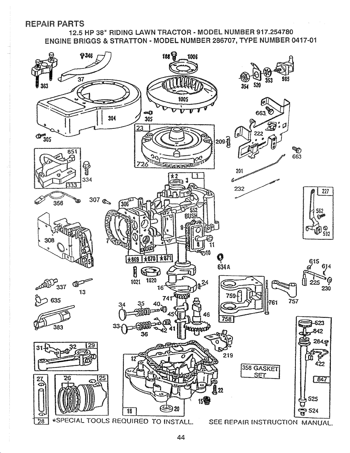
Z
REPAIR PARTS
12.5 HP 38" RIDING LAWN TRACTOR - MODEL NUMBER 917.254780
ENGtNE 8RIGGS & STRATTON - MODEL NUMBER 286707, 3F'{PE NUMBER 0417-01
334
307
13
383
6&3
757
SEE REPAIR tNSTAUCTION MANUAL.
44
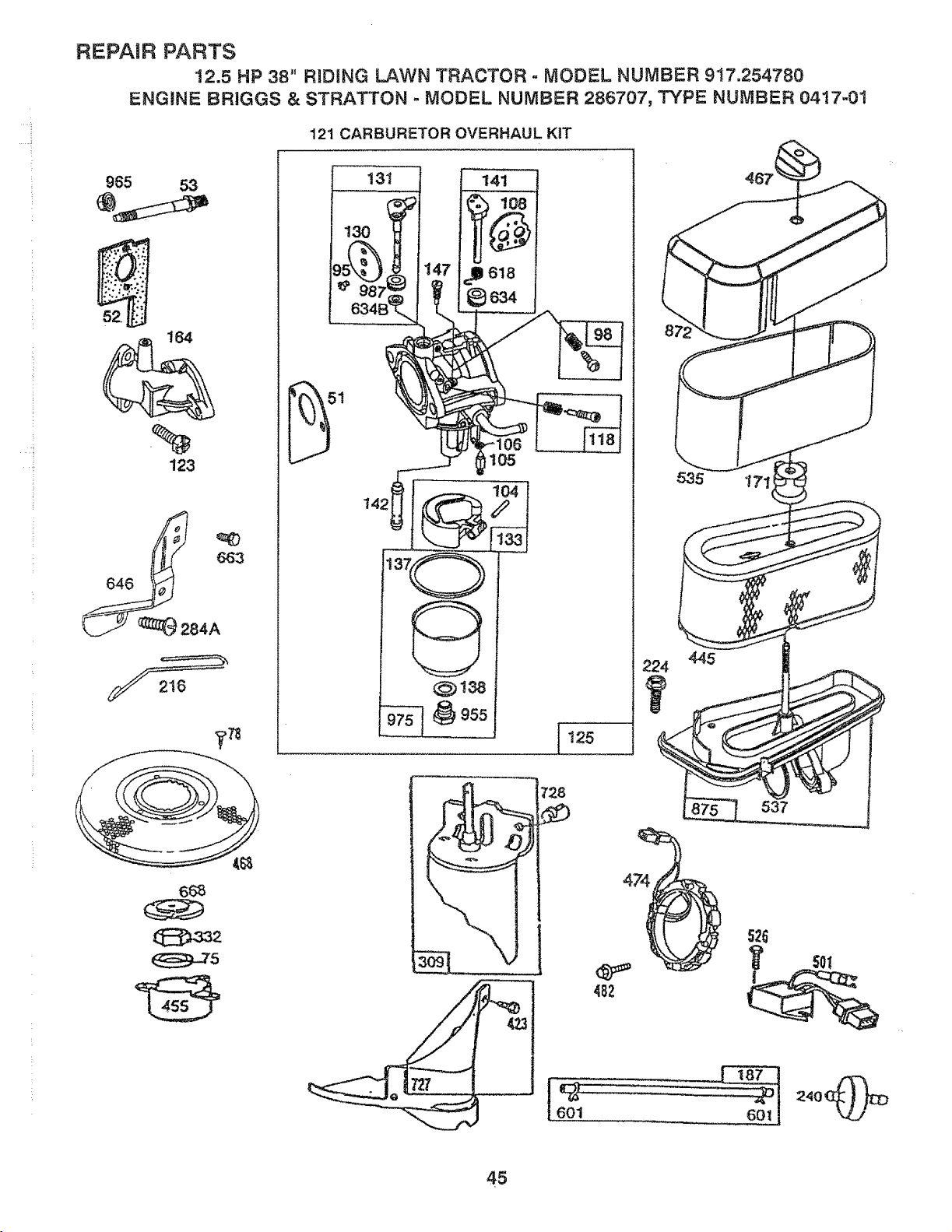
H.
REPAIR PARTS
12.5 HP 38," RiDiNG LAWN TRACTOR ° MODEL NUMBER 917.254780
ENGINE BRiGGS & STRATTON o MODEL NUMBER 286707, TYPE NUMBER 0417-01
121 CARBURETOR OVERHAUL KIT
96-5 53
t64
123
__.J_2e4A
131
130 _
t42t
_138
955
125
_
601
535 !711
482
224 445
7
526
45
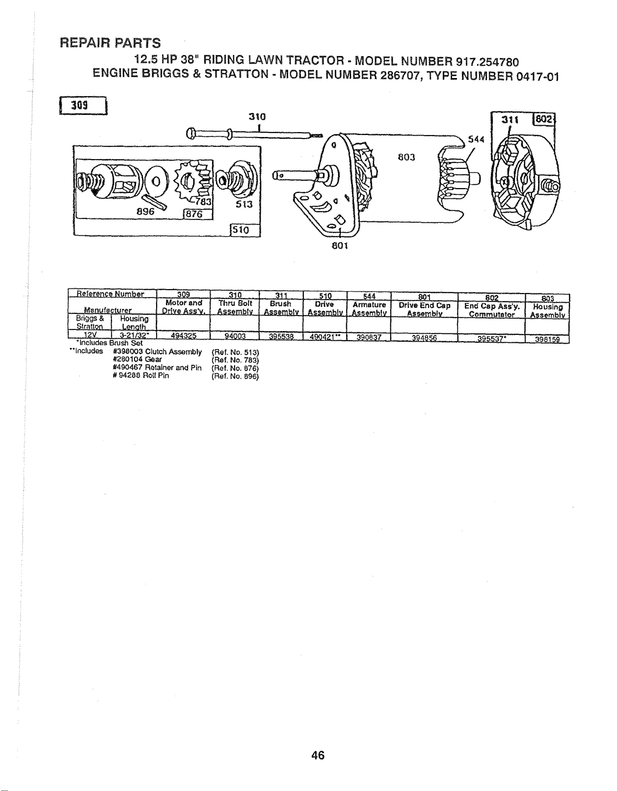
.... i
REPAIR PARTS
12.5 HP 38" RIDING LAWN TRACTOR - MODEL NUMBER 917.254780
ENGINE BRIGGS & STRATTON - MODEL NUMBER 286707, TYPE NUMBER 0417-01
I
80I
803
*includes Brush Set
"'lncJudes #398003 Clutch Assembly
#280104 Geax
#490467 Relainer and Pin
# 94288 Roll Pin
____0
Drive
(Ref. No. 513)
(Rof. No. 783)
(Ref. No. 876)
(Ref. No. 8,96)
4_4z_
46
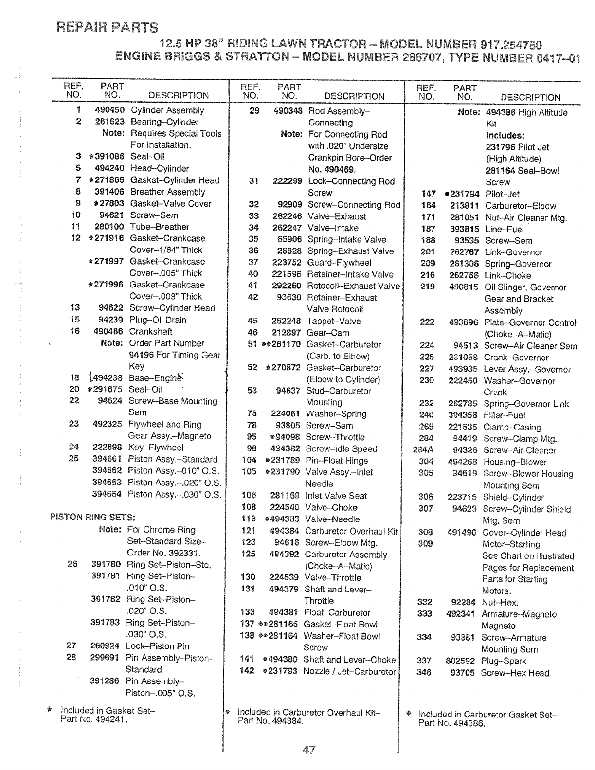
REPAIR PARTS
12_5 HP 38" R!D_NG LAWN TRACTOR - MODEL NUMBER 9!7.254780
ENGINE BRIGGS & STRATTON - MODEL NUMBER 286707, TYPE NUMBER 04t7-0t
REF. PART
NO. NO. DESCRIPTION
I 490450 Cylinder Assembly
2 261623 Bearing-Cylinder
Note: Requires Special Tools
For Installation.
3 _391086 Seal-Oil
5 494240 Head-Cylinder
7 _271866 Gasket-Cylinder Head
8 391408 Breather Assembly
9 _27803 Gasket-Valve Cover
10 94621 Screw-Sere
1! 280100 Tube-Breather
12 _2719!8 Gasket-Crankcase
Cover-I/64" Thick
_271997 Gasket-Crankcase
Cover-.005" Thick
_,271996 Gasket-Crankcase
Cover-.009" Thick
!3 94622 Screw-Cylinder Head
15 94239 Plug-Oit Drain
16 490466 Crankshaft
Note" Order Part Number
94198 For Timing Gear
Key
18 _,494238 Base-Engin_
20 _291675 SeaFOil
22 94624 Screw-Base Mounting
Sem
23 492325 F_ywheei and Ring
Gear Assy.-Magneto
24 222698 Key-Flywheel
25 394661 Piston Assy.-Standard
394662 Piston Assy.-0t0" O.S.
394663 Piston Assy.-o020" O.S.
394664 Piston Assy.-.030" O.S.
P{STON RiNG SETS;
Note: For Chrome Ring
Set-Standard Size-
Order No. 392331.
26 391780 Ring Set-Piston-St&
39t78! Ring Set-Pistorr
.010" O.S.
391782 Ring Set-Piston-
.020" O.S.
391783 Ring Set-Piston-
.030" O.S.
27 260924 Lock-Piston Pin
28 299691 Pin Assembly-Piston-
Standard
391286 Pin Assembly-
Piston-.005" O.S.
* included in Gasket Set-
Part No. 494241.
REF. PART
NO. NO. DESCR!PTION
29 490348 Rod Assembly-
Connecting
Note: For Connecting Rod
with .020" Undersize
Crankpin Bore-Order
No. 490469.
31 222299 Lock-Connecting Rod
Screw
32 92909 Screw-Connecting Rod
33 282246 Valve-Exhaust
34 262247 Valveqntake
35 65906 Spring-intake Valve
36 26828 Spring-Exhaust Valve
37 223752 Guard-Flywheel
40 221596 Retainer-Intake Valve
41 292260 Rotocoil-Exhaust Valve
42 93830 Retainer-Exhaust
Valve Rotocoil
45 262248 Tappet-Valve
46 212897 Gear-Cam
51 ®_281170 Gasket-Carburetor
(Carb. to EIbow)
52 _270872 Gasket-Carburetor
(Elbow to Cylinder)
53 94637 Stud-Carburetor
Mounting
75 224061 Washer-Spring
78 93805 Screw-Sere
95 694098 Screw-Throttle
98 494382 Screw-Idle Speed
104 _231789 Pin-Float Hinge
105 6231790 Valve Assy.-qnlet
Needle
106 281169 Inlet Valve Seat
108 224540 Valve-Choke
118 6494383 Valve-Needle
t21 494384 Carburetor Overhaul Kit
123 94818 Screw-Elbow Mtg.
125 494392 Carburetor Assembly
(Choke-A-Matic)
130 224539 Valve-Throttle
13t 494379 Shaft and Lever-
Throttle
133 494381 Float-Carburetor
137 e_ 281165 Gasket-Float Bowl
138 _®281164 Washer-Ftoat Bowl
Screw
!41 _494380 Shaft and Lever-Choke
142 ®231793 Nozzle/Jet-Carburetor
Included in Carburetor Overhaul Kit-
Part No. 494384.
47
REF. PART
NO. NO. DESCRIPTION
Note:
147 o231794
164 213811
171 281051
187 393815
188 93535
201 262787
209 261306
218 262786
219 490815
222 493896
224 94513
225 231058
227 493935
230 222450
232 282785
240 394358
265 221535
284 94419
284A 94326
304 494288
305 94619
306 223715
307 94623
308 491490
309
332 92284
333 492341
334 93381
337 802592
346 93705
494386 High A_titude
Kit
lnc|udes:
231796 Pilot Jet
(High Altitude)
281164 Seal-Bowl
Screw
Pilot-Jet
Carburetor-Elbow
Nut-Air Cleaner Mtg.
Line-Fuel
Screw-Sem
Link--Governor
Spring-Governor
Link-Choke
Oil Slinger, Governor
Gear and Bracket
Assembly
Plate--Governor Control
(Choke-A_M atic)
Screw-Air Cleaner Sere
Crank-Governor
Lever Assy.-Governor
Washer-Governor
Crank
Spring-Governor Link
Filter-Fuel
C_amp_Casing
Screw-C_amp Mtg,
Screw-AirCleaner
Housing-Blower
Screw-Blower Housing
Mounting Sere
Shield_Cylinder
Screw-CylinderShield
Mtg. Sere
Cover-Cylinder Head
Motor-Starting
See Chart on Iilustrated
Pages for Replacement
Parts for Starting
Motors.
Nut-Hex.
Armature-Magneto
Magneto
Screw-Armature
Mounting Sem
Plug-Spark
Screw-Hex Head
¢ lnctudedin Carbur_or GasketSet-
Part No, 49438&
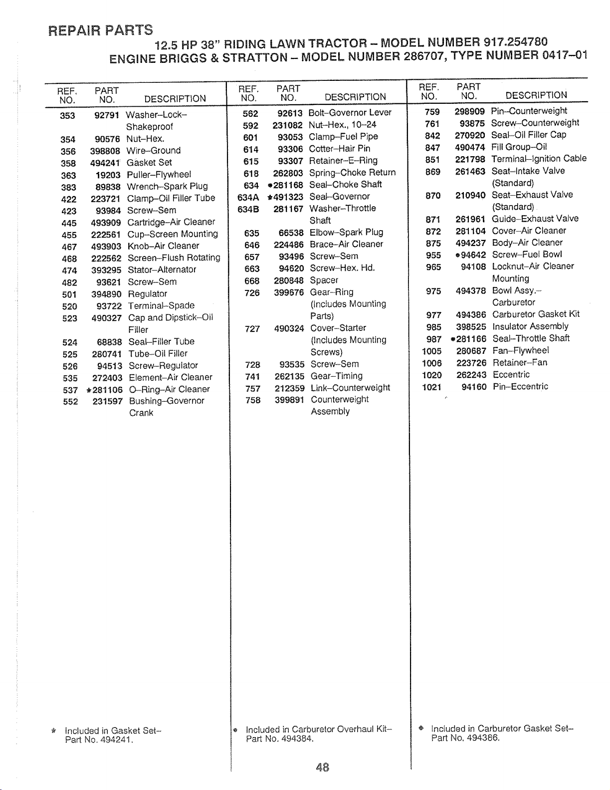
REPAIR PARTS
12.5 HP 38" RIDING LAWN TRACTOR - MODEL NUMBER 917.254780
ENGINE BRIGGS & STRATTON - MODEL NUMBER 286707, TYPE NUMBER 0417-01
REF, PART
NO. NO. DESCRIPTION DESCRIPTION
353 92791
354 90576
356 398808
358 494241'
363 19203
383 89838
422 223721
423 93984
445 493909
455 222561
467 493903
468 222562
474 393295
482 93621
501 394890
520 93722
523 490327
524 68838
525 280741
526 94513
535 272403
537 _281106
552 231597
Includedin Gasket Set-
Part No, 494241,
Washer-Lock-
Shakeproof
Nut-Hex.
Wire-Ground
Gasket Set
Puller-Flywheel
Wrench-Spark Plug
Clamp-Oil Filler Tube
Screw-Sem
Cartridge-Air Cleaner
Cup-Screen Mounting
Knob-Air Cleaner
Screen-Flush Rotating
Stator-Attemator
Screw-Sem
Regulator
Terminal-Spade
Cap and Dipstick-OiI
Filler
Seat-Filter Tube
Tube-Oil Filler
Screw-Regulator
Element-Air Cleaner
O-Ring-Air Cleaner
Bushing-Governor
Crank
REF, PART
NO. NO.
562 92613
592 231082
601 93053
614 93306
615 93307
618 262803
634 o281168
634A _491323
634B 281167
635 66538
646 224486
657 93496
663 94620
668 280848
726 399676
727 490324
728 93535
74! 262135
757 212359
758 399891
DESCRIPTION
Bolt-Governor Lever
N ut-Hex., 10-24
Clamp-Fuel Pipe
Cotter-Hair Pin
Retainer-E-Ring
Spring-Choke Return
Seat-Choke Shaft
Seal-Governor
Washer-Throttle
Shaft
Elbow-Spark Plug
Brace-Air Cleaner
Screw-Sere
Screw-Hex, Hal,
Spacer
Gear-Ring
(Includes Mounting
Parts)
Cover-Starter
(lncIudes Mounting
Screws)
Screw-Sere
Gear-Timing
Link-Counterweight
Counterweight
Assembly
REF. PART
NO. NO.
759 298909 Pin-Counterweight
761 93875 Screw-Counterweight
842 270920 Seal-Oil Filler Cap
847 490474 Fill Group-Oil
851 221798 Terminal--ignition Cable
869 261463 Seat-Intake Valve
(Standard)
870 210940 Seat-Exhaust Valve
(Standard)
87! 261961 Guide-Exhaust Valve
872 281104 Cover-Air Cleaner
875 494237 Body-Air Cleaner
955 e94642 Screw-Fuel Bowl
965 94108 Locknut-Air Cleaner
Mounting
975 494378 Bowl Assy.-
Carburetor
977 494386 Carburetor Gasket Kit
985 398525 Insulator Assembly
987 o281166 Seal-Throttle Shaft
1005 280687 Fan-FtywheeT
1006 223726 Retainer-Fan
1020 262243 Eccentric
1021 94160 Pin-Eccentric
Included in Carburetor Overhaul Kit-
Part No, 494384.
48
¢
Included in Carburetor Gasket Set-
Part No, 494386.

ERVICE OTES
.... !
H
49

RVICE NOTES
50
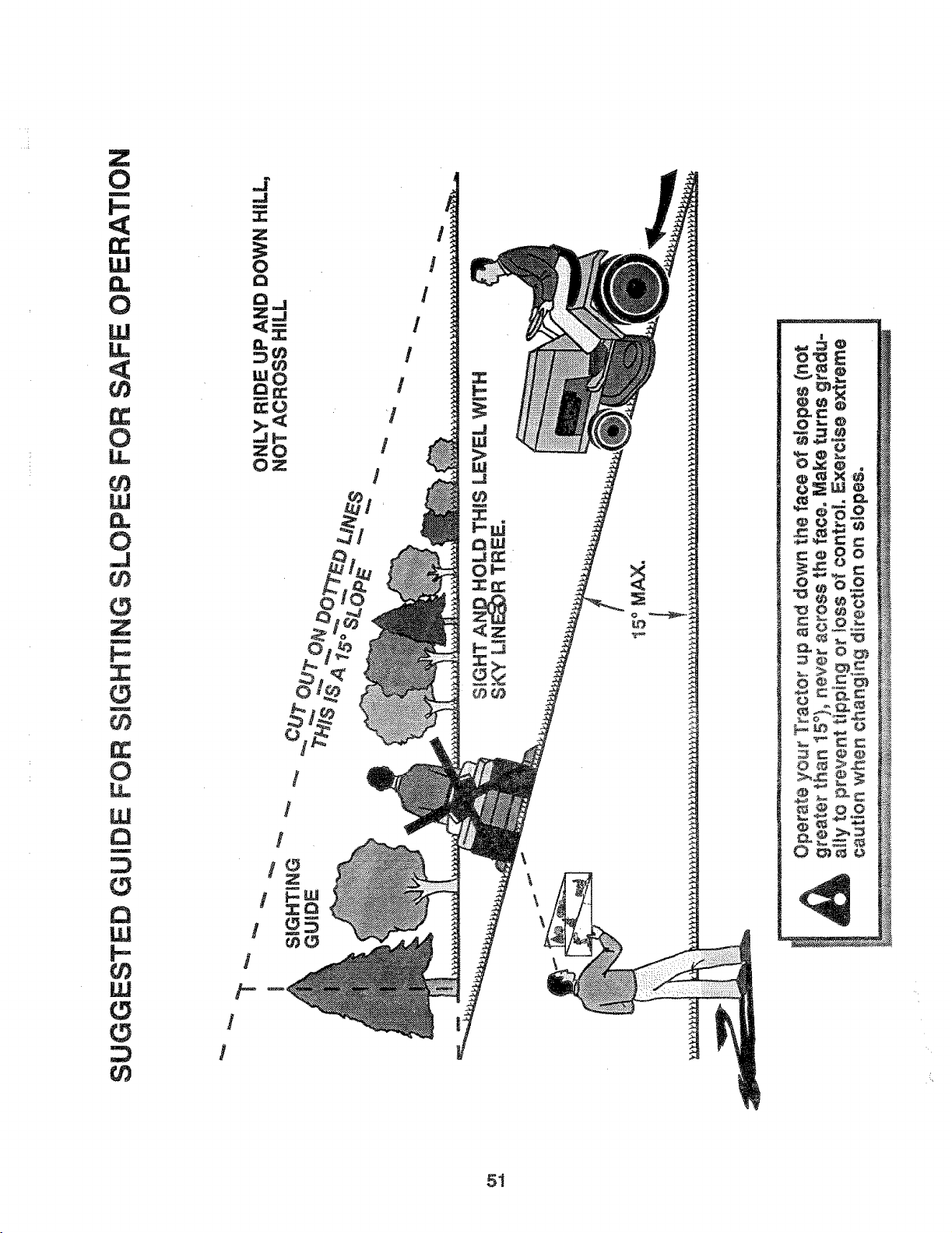
Z
0
I
I-,
<
t_
LL!
0
LU
LL
<
0
W
0
J
r_
Z
N
u
r_
Q_
0
W
a
i
w
F-
LU
r_
r_
51
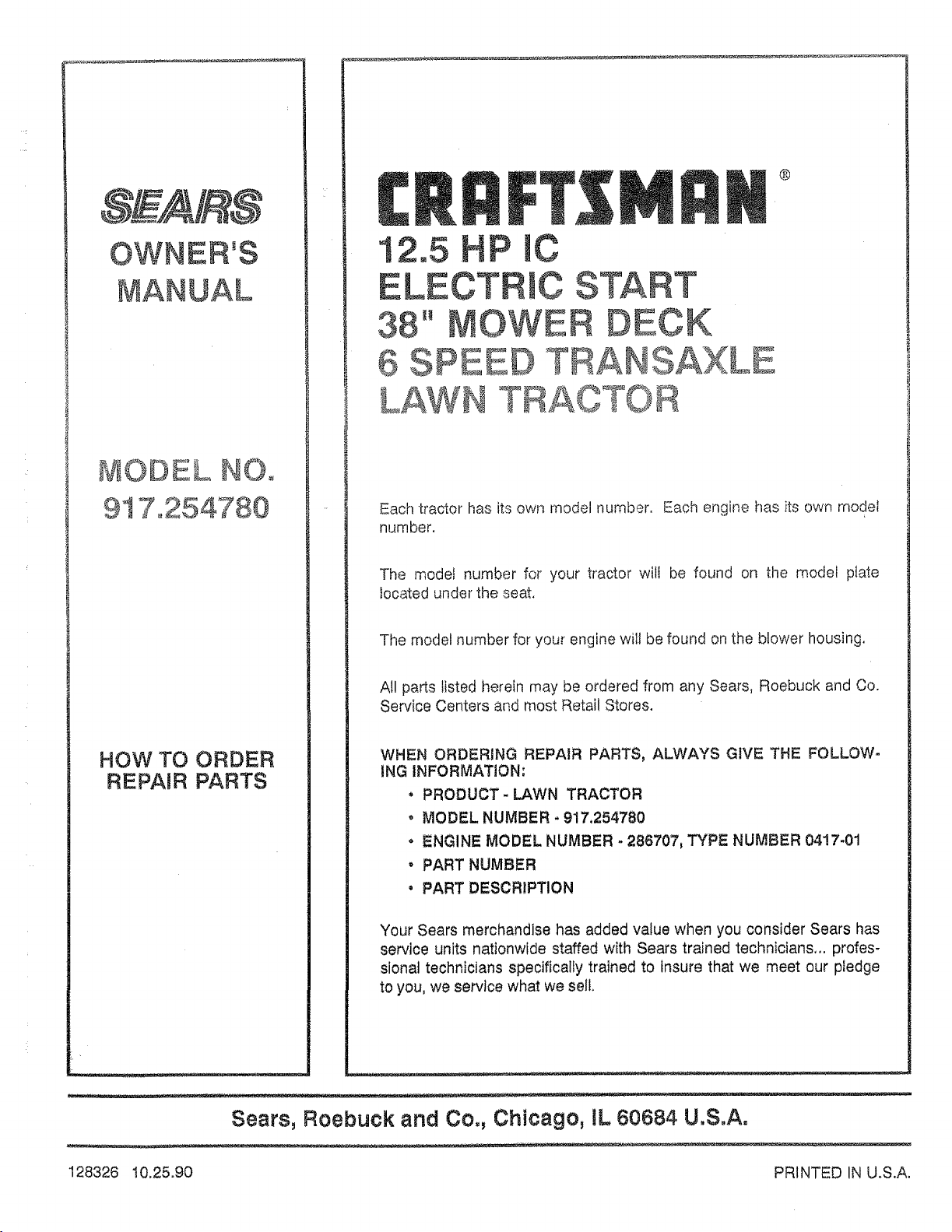
OWNER'S
MANUAL
MODEL NO,
917o254780
HOW TO ORDER
REPAIR PARTS
®
12.5 HP mC
ELECTRIC START
'° ECK
6 SPEE
T
E
Each tractor has its own model number. Each engine has its own model
number.
The model number for your tractor will be found on the model plate
located under the seat,
The model number for your engine will be found on the blower housing.
All parts listed herein may be ordered from any Sears, Roebuck and Co.
Service Centers and most Retail Stores.
WHEN ORDERING REPAIR PARTS, ALWAYS GIVE THE FOLLOW-
ING INFORMATION:
* PRODUCT-LAWN TRACTOR
o MODEL NUMBER - 917.254780
o ENGINE MODEL NUMBER - 288707, TYPE NUMBER 0417-01
, PART NUMBER
, PART DESCRIPTION
Your Sears merchandise has added value when you consider Sears has
service units nationwide staffed with Sears trained technicians,., profes-
sional technicians specificalty trained to Insure that we meet our pledge
to you, we service what we sell.
Sears, Roebuck and Co., Chicago, UL60684 U.S.A.
128326 I0.25.90 PRINTED IN U.S.A.