MODEL NO.
917.254630
Caution:
Read and Follow
A, Safety RuBes
And instructions
Before Operating
This Equipment
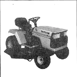
LT 12 PIP ELECTRIC START
4 SPEED =38" WER
LAWN TRACTOR
o Assembly
o Operation
e MaMtenance
o Repair and Adjustment
o Repair Parts
Sears, Roebuck and Co,, Chicago, IL 60684 U,S.A.
.......... :,,, , i ,i,,11 i i,i i,,i,iii i,,i,iii i1,,i iiii

ll=====l_l =,ul Hll ==l=
LOOK FOR THIS SYMBOL TO POINT
OUT IMPORTANT SAFETY PRECAU-
TIONS. IT MEANS - A'I-rENTION! BE-
COME ALERT! YOUR SAFETY tS IN-
VOLVED.
CAUTION: LOOK FOR THIS WORD TO POINT Oi
IMPORTANT EQUIPMENT PRECAUTION
RULES FOR SAFE OPERATfON
WARNING: This unit is equipped with an internal combustion engine and should not be used on or near any unimproved forest-covere
brush-covered or grass covered land unless the engine s exhaust system is equipped with a spark arrestor meeting applicable local or art
laws (if any) If a spark arrestor is used, it should be maintained in effective working order be the operator. {See REPAIR PARTS for pz
number identification).
Inthe State of California the above is required by taw (Section 4442 of the California Public Resources Code). Other States may have simit
laws. Federal laws apply on federal lands
1.1 Know the controls and how to stop quickly. READ THIS
OPERATORS MANUAL and instructions furnished with
attachments.
2. Do not allow children to operate the machine Do not allow
adults to operate it without proper instruction..
3 Do not carry passengers. Do not mow when children and
others are around.
4,. Always wear substantial footwear. Do not wear loose fitting
clothing that could get caught in moving parts
5. Keep your eyes and mind on your tractor, mower, and the
area being cuL Do not let other interests distract you.
6. Do not attempt to operate your tractor or mower when not in
the drivers seat.
7. Always get on or off your tractor from the operator's left hand
side°
8 Clear the work area of objects (wire, rocks, etc )which might
be picked up and thrown°
9. Disengage allattachment clutches before attempting to start
the engine.
10. Disengage power to attachments and stop the engine before
leaving the operator's position..
11_ Disengage power to mower, stopthe engine, and disconnect
spark plug wire(s) from spark plug(s) before cleaning, making
an adjustment, or repair. Be careful to avoid touching hot
muffler or engine components.
12o Disengage power to attachments when transporting or not in
use,,
13o Take alt possible precautions when leaving the vehicle
unattended, Disengage the power4ake-off, lower the attach-
ments, shift into neutral, set the parking brake, stop the
engine, and remove the key_
14. Do not stop or start suddenly when going uphill or downhill.
Mow up and down the face of slopes (not greater than 15°);
never across the face. Refer to page 37.
15. Reduce speed on slopes and make turns gradually to prevent
tipping or loss of control. Exercise extreme caution when
changing direction on slopes.
16, While going up or down slopes, ptace Gear Shift Control
Lever In 1st gear position to negotiate the slope without
stopping
17,. Never mow in wet or slippery grass, when tractionis unsure,
or at a speed which could cause a skid.
18, Stay alert for holes in the terrain and other hidden hazards,
Keep away from drolmoffs,
19. Do not drive too close to creeks, ditches, and public high-
ways.
20. Exercise special care when mowing around fixed objects in
order to prevent the blades from striking them_Never delib-
erately runtractor or mower intoor over any foreign objects
21. Never shift gears until tractor comes toa stop.
22_ Never place hands or feet under the mower, in discharge
chute, or near any moving parts while tractor or mower are
running. Always keep clear of discharge chute,.
23° Use care when pulling loads or using heavy equipment.
a. Use only approved drawbar hitch points°
b. Limit loads to those you can safely control..
c. Do not turn sharply Use care when backing.
d_ Use counterweight orwheel weights when suggested
owner's manuals.
24. Watch out for traffic when crossing or neat roadways
25 When using any attachments, never direct discharge
material toward bystanders nor allow anyone near the v
hlcle while in operation
26 Handle gasoline with care - it is highly flammable.
a. Use approved gasoline contatners.
b. Never remove the fuel cap of the fuel tank or ac
gasoline to a runningor hot engine or an engine that h_
not been allowed to cool for several minutes after ru_
ning. Never fill tank indoors, aiways clean up spill_
gasoline.
c Open doors if the engine is run in the garage - exhau
fumes are dangerous_ Do not run the engine indoors
27 Keep the vehicle and attachments in good operating conc
tion, and keep safety devices in place and working
28. Keep all nuts, bolts, and screws tight to be sure the equiI
ment is in safe working condition
29. Never store the equipment with gasoline in the tank inside
buildir_g where fumes may reach an open frame or spar
Allow the engine to coot before storing in any enclosure
30. To reduce fire hazard, keep the engine free of grass, leave
or excessive grease_ Do not clean product while engine
running
31.. Except for adjustments, DO NOT operate Engine if
cleaner or cover directly over carburetor air intake is r_
moved.. Removal of such part could create a fire hazard.
32. Do not operate without a muffler, or tamper with exhau
system Damaged mufflers or spark arresters coufd create
fire hazard. Inspect periodically and replace if necessary.
33 The vehicle and attachments should be stopped and i_
spected for damage after striking a foreign object, and tl"
damage should be repaired before restarting and operatin
the equipment.
34 Do not change the engine governor settings or overspeed th,
engine; severe damage or injury may result.
35. When using the vehicle with mower, proceed as follows:
a. Mow only in daytight or in good artificial light.
b. Shut the Engine off when unclogging chute
c. Check the blade mounting bolts for proper tightness z
frequent intervals.
36. Do not operate the mower without either the entire gras
catcher, on mowers so equipped, or the the deflector shiel
in place..
37. Disengage power to mower before backing UpoDo not mo_
in reverse unless absolutely necessary and then only aft_
careful observation of the entire area behind the mower.
38. Under normal usage the grass catcher bag material is subje_
to deterioration and wear. Itshould be checked frequently fc
bag replacement Replacement bags should be checked t
ensure compliance with the original manufacturer's recorr
mendations or specifications.
CONGRATULATIONS on your purchase of a Sears
Lawn Tractor° it has been designed, engineered and
manufactured to give you the best possible dependabili-
ty and performance. Should you experience any pro-
blem you cannot easily remedy, please contact your
nearest Sears Service Department. We have compe-
tent, well-trained technicians and the proper tools to
service or repair this unit_
MAINTENANCE AGREEMENT
A Sears Maintenance Agreement is available on this
product, See the nearest Sears store or service center
for details.
SERIAL
NUMBER
DATE OF PURCHASE
THE SERIAL NUMBER WILL BE FOUND ON
THE MODEL PLATE UNDER THE SEAT°
YOU SHOULD RECORD THESE NUMBERS
AND KEEP FOR FUTURE REFERENCE°
CUSTOMER RES_NS/MLITIES
Read and retain this manual Study and observe the safety rules. Always use care when using your tractor
Always keep your tractor and mower clean, Follow a regular schedule in maintaining, caring for, and using
your tractor. A well cared for tractor will run better and last longer
A TTACHMENTS
This unit can use many attachments now available at your Sears store_ It cannot use attachments that engage
the ground like a plow, harrow, cultivator, or tiller See page 50 for a list of available attachments
LIMITED ONE YEAR WARRANTY
ON ELECTRIC START RIDING EQUIPMENT
For one year from date of purchase, when this riding equipment is maintained, lubricated, and tuned up accor_
ding to the operating and maintenance instruction in the owner's manual, Sears will repair free of charge any
defect in material or workmanship in this electric start riding equipment
This warranty excludes blade(s), blade adapter(s), spark plug(s) air cleaner and belt(s), which are expendable
and become worn during normal use
This warranty does not cover:
Tire replacement or repair caused by punctures from outside objects (such as nails, thorns, stumps,
or glass); and
- repairs necessary because of operator abuse or negligence, including the failure to maintain the equip-
ment according to instructions contained in the owner's manual; and
riding equipment used for commercial or rental purposes,
FULL 90-DAY WARRANTY ON BATTERY
For 90 days from the date of purchase, if any battery included with this riding equipment proves defective in
material or workmanship and our testing determines the battery will not hotd a charge, Sears will replace the
battery at no charge°
WARRANTY SERVICE IS AVAILABLE BY CONTACTING THE NEAREST SEARS SERVICE CENTER/DEPARTMENT
IN THE UNITED STATES_ This warranty applies only while this product is in use in the United States
This warranty gives you specific legal rights, and you may also have other rights which may vary from state
to state_
SEARS, ROEBUCK and COo, Di731CR-W, Sears Tower, Chicago, II 60684
3

A
Adjustments:
Brake 74
Carburetor 78
Mower Drive Belt 22
Mower
Front-to-Rear 22
Side _to-Side 22
Throttle Control Cable 18
Engine Valves 78
Air Filter
Cleaning 76
Element __ 76
Air Intake Screen, Eng _ 16
Assembly 5-8
Attachments . 50
Battery:
Charging
Cleaning
Installation
Levels
Preparation
Starting with Weak Battery
Storage
Terminals
Belt:
Motion Drive Replacement
Mower Drive Adjustment
Mower Drive,
Remove/Replace
Bla de:
Sharpening
Replacement
Brake Adjustment
C
Carburetor Adjustment lB
Controls, Tractor 9
Cutting Level, Mower 12
E
Engine:
Air Screen 16
Oil Change t 6
Oil Level t6
Oil Type t 6
Starting 10
Storage 23
Valve Adjustments 18
F
Filter:
Air ..............................................................16
Fuel ........................................................18
Fuel:
Type 10
Storage 23
Type 10
Storage 23
Fuse 20
H
Hood Removal 20
L
Levelling Mower Deck 22
Lubrication:
Chart 24
Tractor Pivot Points 17
M
Maintenance 13
Air Filter 16
7 Air Filter Element 16
15 Air Screen 16
8 Battery 15
t 5 Blade Sharpening 14
7 Brake Adjustment t4
17 Engine Off 16
23 Fuel Filter 18
t 5 Lubrication Chart 24
Spark Plug 18
t 9 Tire Care 14
22 Mower:
Adjustment, Front-to-Rear 23
21 Adjustment, Side-to-Side 22
Blade Sharpening 14
t4 Blade Replacement 14
14 Cutting Level 12
14 #)stallation 21
Operation 1 t
Removal 20
Muffler t 7
Spark Arrester 2
0
Oil:
Cold Weather Conditions 15
Engine 16
Storage 23
Operation 9- 12
Operating Your Mower 1!
Operating Your Tractor l l
Starting the Engine 11
Stopping Your Tractor 10
Tractor Operation on Hills 12
Options:
Attachments 50
Spark Attester 2
4
P
Parking Brake
Parts Bag
R
Repair and Adjustments
Blade° , .
Carburetor
Fuse
Hood Removal
Motion Drive Belt
Replacement
Mower Drive Belt
Replacement
Mower Adjustment
Side-to-Side
Mower Removal
S
Safety Rules
Seat
Service Record
Slope Guide Sheet
Spark Plug
Speed Control Chart
Starting the Engine
Steering Wheel
Stopping the Tractor
Storage
T
Throttle Control Cable
Adjustment
Tires
Trouble Shoot#_g Chart
V
Valves Adjustments
W
Warranty
Wiring (Schematic)
9
5-6
14-24
15
t8
20
20
10
20
22
20
2
7
13
51
t8
12
tl
5
70
23
18
t4
25
18
3
27
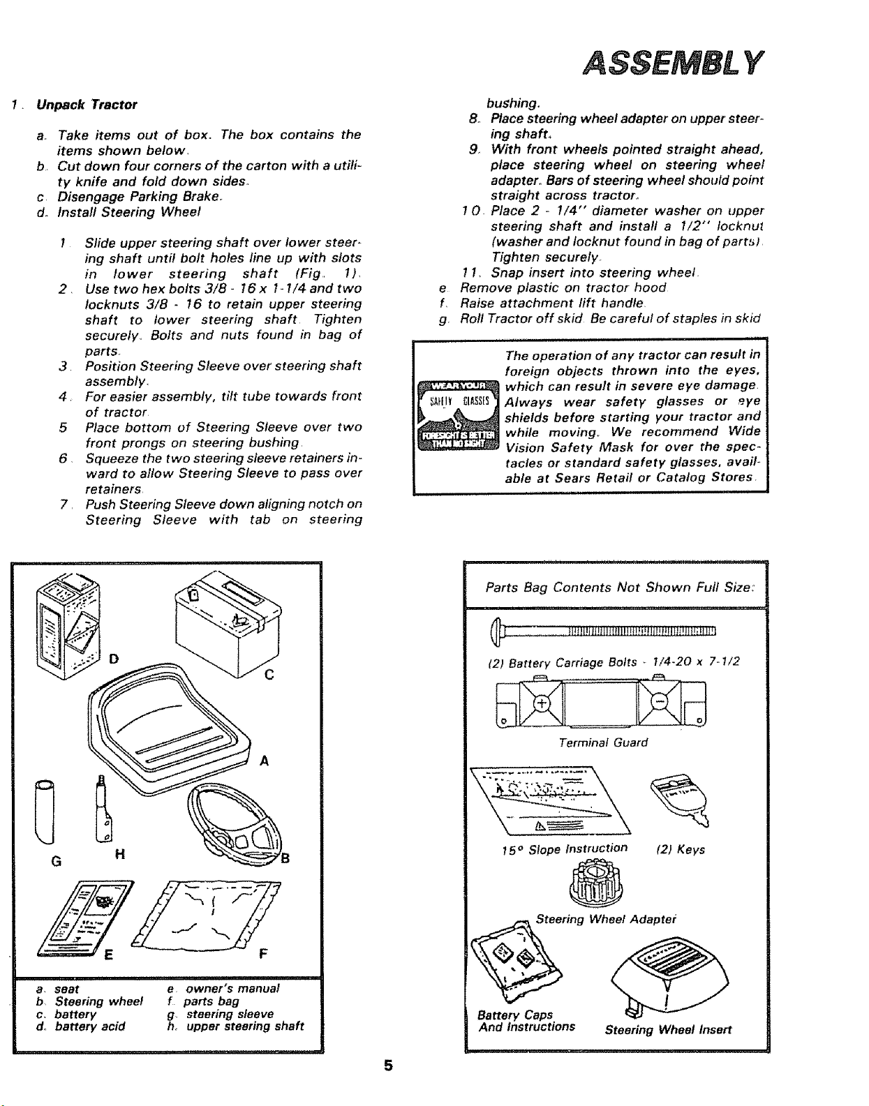
Unpack Tractor
a, Take items out of box. The box contains the
items shown below.
b Cut down four corners of the carton with a utili-
ty knife and fold down sides.
c Disengage Parking Brake.
d. Install Steering Wheel
I Slide upper steering shaft over lower steer _
ing shaft until bolt holes line up with slots
in lower steering shaft (Fig 1),
2, Use two hex bolts 3/8- 16 x t- 1/4 and two
Iocknuts 3/8 - t6 to retain upper steering
shaft to lower steering shaft Tighten
securely,, Bolts and nuts found in bag of
parts.
3 Position Steering Sleeve over steering shaft
assembly.
4 For easier assembly, tilt tube towards front
of tractor
5 Place bottom of Steering Sleeve over two
front prongs on steering bushing,
6 Squeeze the two steering sleeve retainers in-
ward to allow Steering Sleeve to pass over
retainers
7, Push Steering Sleeve down aligning notch on
Steering Sleeve with tab on steering
Y
e
f,
g,
bushing.
Bo Place steering wheel adapter on upper steer-
ing shaft.
9. With front wheels pointed straight ahead,
place steering wheel on steering wheel
adapter,, Bars of steering wheel should point
straight across tractor°
I O. Place 2 - !/4" diameter washer on upper
steering shaft and install a I/2"" locknuZ
(washer and Iocknut found in bag of part_)
Tighten securely.
11_ Snap insert into steering wheel.
Remove plastic on tractor hood
Raise attachment rift handle
Rol! Tractor off skid Be careful of staples in skid
The operation of any
foreign objects thrown into the eyes,
which can result in severe eye damage,
Always wear safety glasses or eye
shields before starting your tractor and
while moving,. We recommend Wide
Vision Safety Mask for over the spec-
tacles or standard safety glasses, avail-
able at Sears Retail or Catalog Stores
illl,llrl
Q
1
F
,, , illll,lllll, ..........
a. seat e owner's manua!
b, Steering wheel f parts bag
c, battery g, steering sleeve
d° battery acid h_ upper steering shaft
,,,i ,11 ,, ,i i i, iiiii i,ii, ,i i1,, ,i,ill ,,
Parts Bag Contents Not Shown Full Size:
(21 Battery Carriage Bolts _ 1/4-20 x 7-1/2
Terminal Guard
t 5° Slope Instruction (21 Keys
@
Battery Caps
And Instructions Steering Wheel Insert
A_
ASSEMBL Y
LOCATiON
BATTERY
BATTERY
TERMINALS
Y
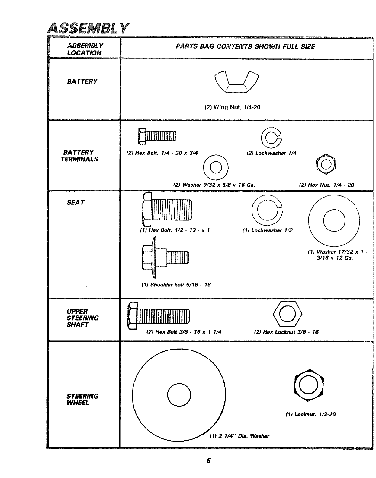
PARTS BAG CONTENTS SHOWN FULL SIZE
....... i ....
(2) Wing Nut, 1/4-20
(2) Hex Bolt, 1/4 - 20 x 3/4
©
t2) Lockwasher I/4 Q
{2) Washer 9/32 x 5/8 x 16 Ga (2) Hex Nut, 1/4 - 20
L
L_
(1) Flex Bolt, 1/2 - 13 - x 1
p,...
{1) Shoulder bolt 5/16 _ 18
E
UPPER
s...,, ililllliltlilillltiiil]
SHAFT ...j
{2) Hex Bolt 3/8 - 16 x 1 1/4
i
STEER,N_ 1 0 t
WHEEL
___ff) 21/4"' Ota. Washer
(1) Lockwasher 1/2
12) Hex Locknut 3/8 - 16
(1) Washer 17/32 x 1
3/16 x 12 Gad
tl) LocknuL 1/2-20
6
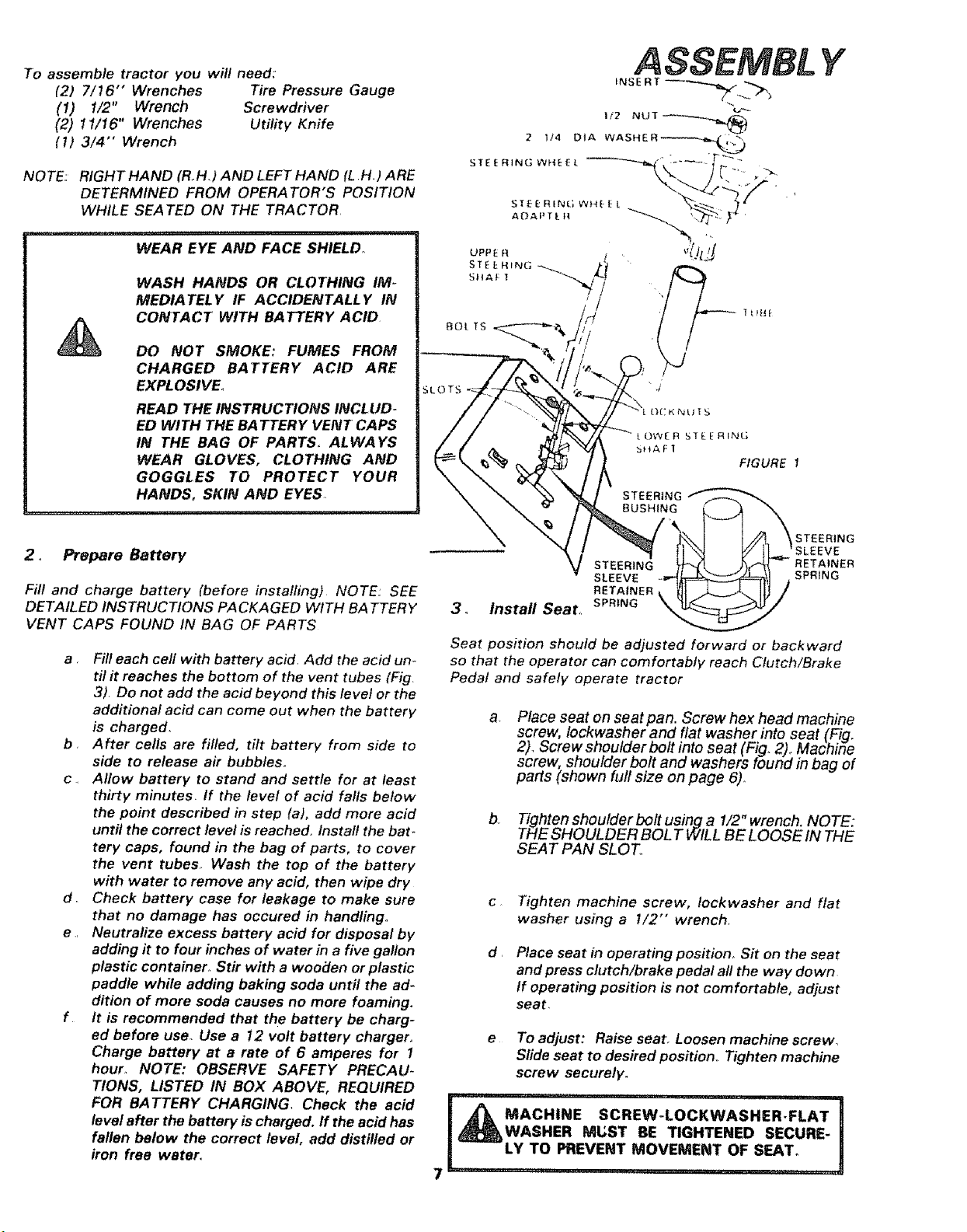
To assemble tractor you wit! need:
(21 7/16" Wrenches Tire Pressure Gauge
(I) 1/2" Wrench Screwdriver
(2) ! 1/16" Wrenches Utility Knife
(I) 3/4" Wrench
NOTE: RIGHT HAND (R.H) AND LEFT HAND (L H,) ARE
DETERMINED FROM OPERATOR'S POSITION
WHILE SEATED ON THE TRACTOR
WEAR EYE AND FACE SHIELD.
WASH HANDS OR CLOTHING IM-
MEDIATELY IF ACCIDENTALLY IN
CONTACT WITH BATTERY ACID
DO NOT SMOKE: FUMES FROM
CHARGED BATTERY ACID ARE
EXPL OSIVE,
READ THE INSTRUCTIONS INCLUD-
ED WITH THE BATTERY VENT CAPS
IN THE BAG OF PARTS. ALWAYS
WEAR GLOVES, CLOTHING AND
GOGGLES TO PROTECT YOUR
HANDS, SKIN AND EYES
OWER S_fEE R_NG
bHAFI
FIGURE
STEERING
BUSHING
Y
2_ Prepare Battery
Fill and charge battery (before instalfing) NOTE: SEE
DETAILED INSTRUCTIONS PACKAGED WITH BATTERY
VENT CAPS FOUND IN BAG OF PARTS
b
c
d
e.,
f
Fill each cell with battery acid, Add the acid un-
til it reaches the bottom of the vent tubes (Fig
3). Do not add the acid beyond this level or the
additional acid can come out when the battery
is charged,
After cells are rifled, titt battery from side to
side to release air bubbles.
Allow battery to stand and settle for at least
thirty minutes. If the level of acid falls below
the point described in step (a), add more acid
until the correct level is reached. Instafl the bat-
tery caps, found in the bag of parts, to cover
the vent tubes° Wash the top of the battery
with water to remove any acid, then wipe dry
Check battery case for leakage to make sure
that no damage has occured in handling°
Neutralize excess battery acid for disposal by
adding it to four inches of water in a five gallon
plastic container° Stir with a wooden or plastic
paddle while adding baking soda until the ad-
dition of more soda causes no more foaming.
tt is recommended that the battery be charg-
ed before use. Use a 12 volt battery charger°
Charge battery at a rate of 6 amperes for I
hour, NOTE: OBSERVE SAFETY PRECAU-
TIONS, LISTED IN BOX ABOVE, REQUIRED
FOR BATTERY CHARGING. Check the acid
level after the battery is charged, ff the acid has
fallen below the correct level, add distilled or
iron free water.
V STEERING
SLEEVE
RETAINER
3. instal Seat.. SPRING
STEERING
RETAINER
SPRING
Seat position should be adjusted forward or backward
so that the operator can comfortably reach Clutch/Brake
Pedal and safely operate tractor
Place seat on seat pan. Screw hex head machine
screw, Iockwasher and flat washer into seat (Fig,
2). Screw shoulder bolt into seat (Fig. 2),,Machirfe
screw, shoulder bolt and washers found in bag of
parts (shown full size on page 6),
b. Tighten shoulder bolt using a I/2" wrench. NOTE:
THE SHOULDER BOL T WILL BE LOOSE IN THE
SEAT PAN SLOT
c Tighten machine screw, Iockwasher and flat
washer using a t/2" wrench,
d,
Place seat in operating position_ Sit on the seat
and press clutch/brake pedal al! the way down
If operating position is not comfortable, adjust
seat,
e To adjust: Raise seat. Loosen machine screw,
Sfide seat to des#ed position. Tighten machine
screw securely.
MACH"E SC.EW: OC,WASHER.,,"AT!
WASHER ML;ST BE TIGHTENED SECURE-
LY TO PREVENT MOVEMENT OF SEAT. ,
ASSEMBL Y
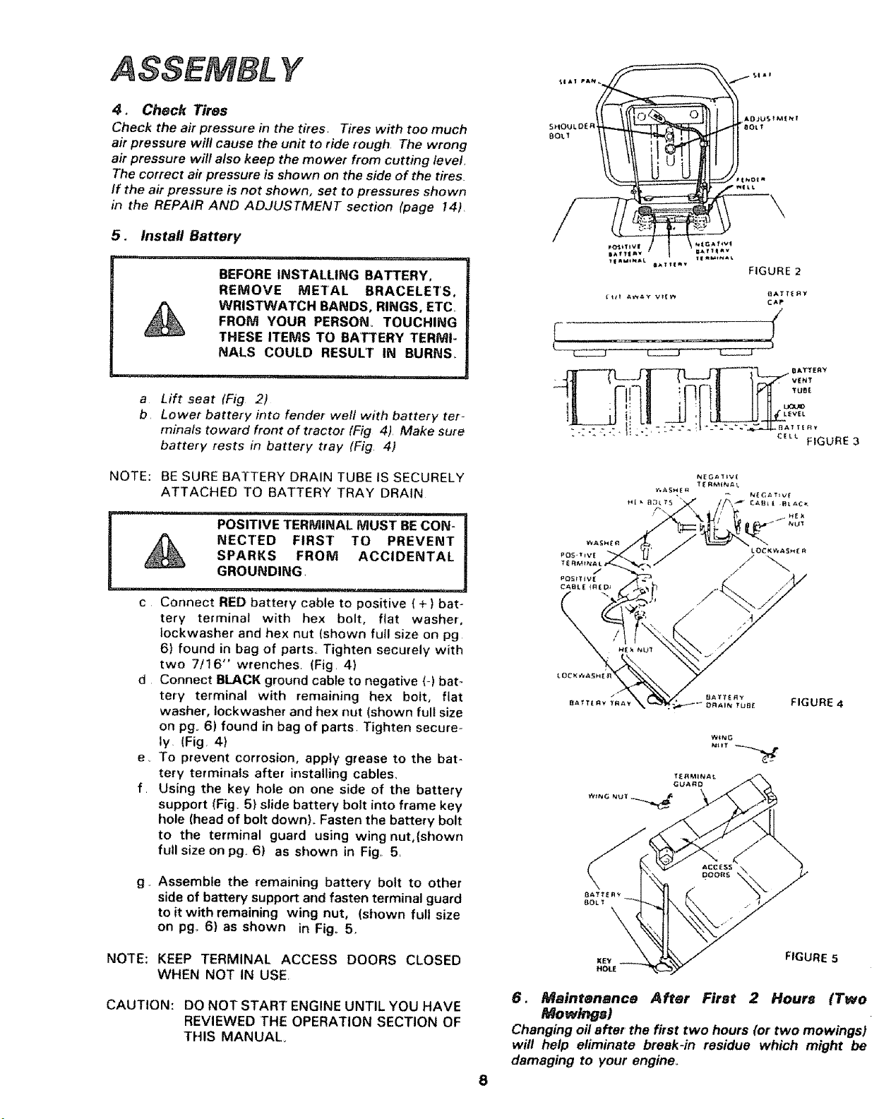
4. Check Tires
Check the air pressure in the tires, Tires with too much
air pressure will cause the unit to ride rough, The wrong
air pressure will also keep the mower from cutting level
The correct air pressure is shown on the side of the tires.
If the air pressure is not shown, set to pressures shown
in the REPAIR AND ADJUSTMENT section (page 14).
5. Install Battery
,nn,, =
" H,HH
BEFORE INSTALLING BATTERY,
REMOVE METAL BRACELETS,
WRISTWATCH BANDS, RINGS, ETC.
FROM YOUR PERSON° TOUCHING
THESE ITEMS TO BATTERY TERMI-
NALS COULD RESULT IN BURN&
a Lift seat (Fig 2)
b Lower battery into fender weft with battery ter-
minals toward front of tractor (Fig 4) Make sure
battery rests in battery tray (Fig 4)
) C AD.tUS f _Nr
_ _MtNAL _AIIIR _
FIGURE 2
{t#t AWAY Vt{W BAIT{RY
CAP
NOTE: BE SURE BATTERY DRAIN TUBE iS SECURELY
ATTACHED TO BATTERY TRAY DRAIN
POSITIVF'TERMINAL CO'N-
Must i
NECTED FIRST TO PREVENT _
E
SPARKS FROM ACCIDENTAL I
GROUNDING, ,,,, J
,=,,= ,=,===, ,,
c Connect RED battery cable to positive ( + ) bat-
tery terminal with hex bolt, flat washer,
tockwasher and hex nut (shown full size on pg
6) found in bag of parts. Tighten securely with
two 7/16" wrenches (Fig. 4)
d Connect BLACK ground cable to negative (-) bat_
tery terminal with remaining hex bolt, flat
washer, tockwasher and hex nut (shown full size
on pg. 6) found in bag of parts Tighten secure-
ly (Fig, 4)
e To prevent corrosion, apply grease to the bat-
tery terminals after installing cables,
f Using the key hole on one side of the battery
support (Fig. 5) slide battery bolt into frame key
hole (head of bolt down). Fasten the battery bolt
to the terminal guard using wing nut,(shown
full size on pg, 6) as shown in Fig, 5,
FIGURE 4
g_ Assemble the remaining battery bolt to other
side of battery support and fasten terminal guard
to it with remaining wing nut, (shown full size
on pgo 6) as shown in Fig. 5.
NOTE: KEEP TERMINAL ACCESS DOORS CLOSED
WHEN NOT IN USE.
CAUTION: DO NOT START ENGINE UNTIL YOU HAVE
REVIEWED THE OPERATION SECTION OF
THIS MANUAL
FIGURE 5
6. Maintenance After First 2 Hour_ {Two
Mow/ng )
Changing oil after the first two hours (or two mowings)
will help eliminate break-in residue which might be
damaging to your engine°
TION
Light
Ignition
Throttle/Choke
Clutch/Brake Pedal
Height
Adjustment ......
Knob
Gear Shift Lever _J_
Attachment
Lift Lever
Attachment Clutch
Lever
Parking Brake
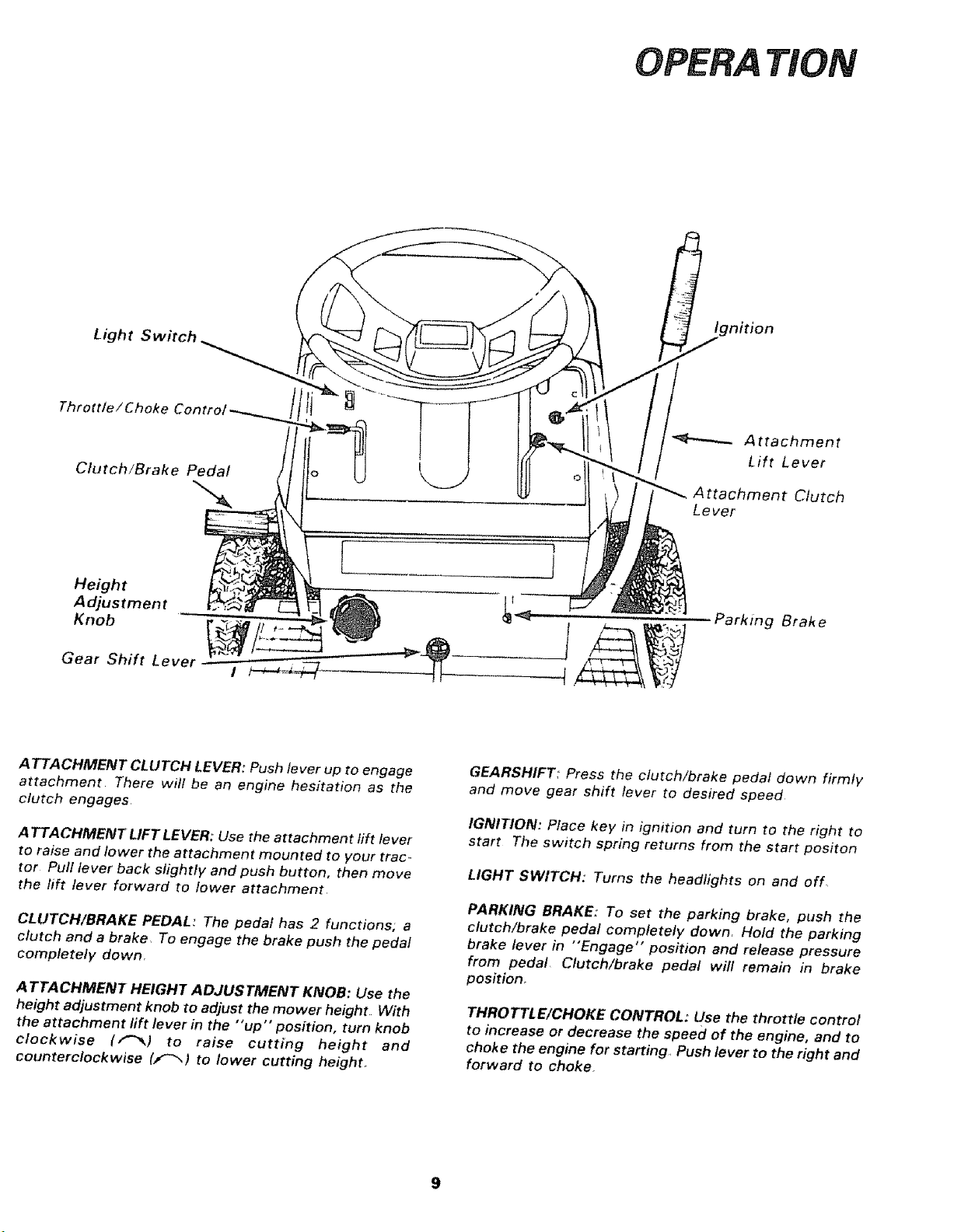
ATTACHMENT CLUTCH LEVER: Push lever up to engage
attachment There will be an engine hesitation as the
clutch engages
ATTACHMENT LIFT LEVER:' Use the attachment rift lever
to raise and lower the attachment mounted to your trac _
tor Pull lever back slightly and push button, then move
the lift lever forward to lower attachment.
CLUTCH/BRAKE PEDAL: The pedal has 2 functions; a
clutch and a brake, To engage the brake push the pedal
completely down.
A TTACHMENT HEIGHT ADJUSTMENT KNOB: Use the
height adjustment knob to adjust the mower height With
the attachment lift lever in the "up" position, turn knob
clockwise (,"'_) to raise cutting height and
counterclockwise (J,_',) to lower cutting height.
GEARSHIFT: Press the clutch/brake pedal down firmly
and move gear shift lever to desired speed
IGNITION: Place key in ignition and turn to the right to
start The switch spring returns from the start positon
LIGHT SWITCH:' Turns the headlights on and off.
PARKING BRAKE: To set the parking brake, push the
clutch/brake pedal completely down, Hold the parking
brake lever in "Engage" position and release pressure
from pedal, Clutch/brake pedal will remain in brake
position.
THROTTLE/CHOKE CONTROL: Use the throttle control
to increase or decrease the speed of the engine, and to
choke the engine for starting,, Push lever to the right and
forward to choke
TION
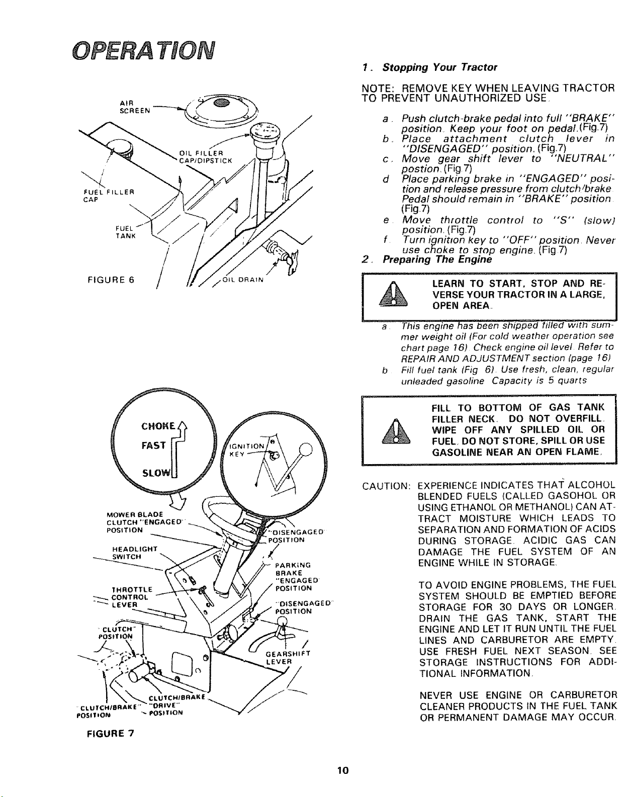
AIR
SCREEN
TANK
/
FIGURE 6 /
MOWER BLADE
CLUTCH'ENGAGED_'_...
POSITION
HEADLIGHT
THROTTLE
"_,_CONTROL
"--_LEVER
FIGURE 7
NGAGED
pOSITION
/
PARKING
BRAKE
*'ENGAGED
-DISENGAGED _
ITtON
/
GEARSHIFT
LEVER
1o Stopping Your Tractor
NOTE: REMOVE KEY WHEN LEAVING TRACTOR
TO PREVENT UNAUTHORIZED USE_
,,
a Push clutch-brake pedal into full "BRAKE"
position Keep your foot on pedal,(Fig7)
b, Place attachment clutch lever in
...... i 7
DISENGAGED position. (Fg.) ,,
c, Move gear shift lever to "'NEUTRAL
postion_ (Fig 7)
d Place parking brake in "'ENGAGED" posi-
tion and release pressure from clutch/brake
Pedal should remain in "BRAKE" position
(Fig7)
e Move thtottte control to "S" (slow)
position (Fig7)
f Turn ignition key to "OFF" position Never
use choke to stop engine, (Fig 7)
Preparing The Engine
- _n "he as been sh_p_ fifted--t sum.
met weight oil (For cold weather operation see
chart page 161 Check engine oil level Refer to
REPAIR AND ADJUSTMENT section (page 16)
b Fill fuel tank (Fig 6) Use fresh, clean, regular
unleaded gasoline Capacity is 5 quarts
nil lllli lU
FILL TO BOTTOM OF GAS TANK
FILLER NECK, DO NOT OVERFILL,
WIPE OFF ANY SPILLED OIL OR
FUEL, DO NOT STORE, SPILL OR USE
GASOLINE NEAR AN OPEN FLAME
CAUTION:
EXPERIENCE INDICATES THA]: ALCOHOL
BLENDED FUELS (CALLED GASOHOL OR
USING ETHANOL OR METHANOL) CAN AT-
TRACT MOISTURE WHICH LEADS TO
SEPARATION AND FORMATION OF ACIDS
DURING STORAGE ACIDIC GAS CAN
DAMAGE THE FUEL SYSTEM OF AN
ENGINE WHILE 1N STORAGE,
TO AVOID ENGINE PROBLEMS, THE FUEL
SYSTEM SHOULD BE EMPTIED BEFORE
STORAGE FOR 30 DAYS OR LONGER,
DRAIN THE GAS TANK. START THE
ENGINE AND LET tT RUN UNTIL THE FUEL
LINES AND CARBURETOR ARE EMPTY.
USE FRESH FUEL NEXT SEASON. SEE
STORAGE INSTRUCTIONS FOR ADDI-
TIONAL _NFORMATION,
NEVER USE ENGINE OR CARBURETOR
CLEANER PRODUCTS )N THE FUEL TANK
OR PERMANENT DAMAGE MAY OCCUR
10
3o Starting The Engine
a Move throttle controllever [Fig,, 7) past "'FAST'"
to the "'CHOKE" position,
b, Turn ignition key to "START" and release key
as soon as engine starts
CAUTION: DO NOT RUN STARTER CONTINUOUSLY
FOR MORE THAN FIFTEEN SECONDS PER
MINUTE
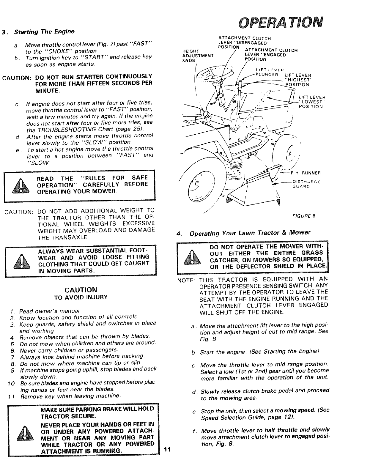
HEIGHT
ADJUSTMENT
KNOB
TION
ATTACHMENT CLUTCH
LEVER °*DISENGAGED"
POSITION
ATTACHMENT CLUTCH
LEVER "ENGAGED'
POSITION
LIFT LEVER
LIFT LEVER
"HIGHEST'
OStTtON
c If engine does not start after four or five tries,
move throttle control lever to "FAST" position,
wait a few minutes and try again if the engine
does not start after four or five more tries, see
the TROUBLESHOOTING Chart {page 25)
d After the engine starts move throttle control
lever slowly to the "SLOW" position
e To start a hot engine move the throttle control
lever to a position between "FAST" and
"SLOW"
.......................... i , i i, ,i ii
A READ THE "RULES FOR SAFE
OPERATION" CAREFULLY BEFORE
OPERATING YOUR MOWER
CAUTION: DO NOT ADD ADDITIONAL WEtGHT TO
THE TRACTOR OTHER THAN THE OP-
TIONAL WHEEL WEIGHTS EXCESSIVE
WEIGHT MAY OVERLOAD AND DAMAGE
THE TRANSAXLE
L ......... ALWAYS WEAR sU'BSTAN'TIAL FOOT- '
A WEAR AND AVOID LOOSE FITTING
CLOTHING THAT COULD GET CAUGHT
.....IN MOVING PARTS: ....................
CAUTION
TO AVOID INJURY
1, Read owner's manual
2. Know location and function of all controls
3 Keep guards, safety shield and switches in place
and working,
4. Remove objects that can be thrown by blades,
5 Do not mow when children and others are around
6 Never carry children or passengers,
7 Always look behind machine before backing,
8,, Do not mow where machine can tip or slip
9 If machine stops going uphifl, stop blades and back
slowly down,
1O, Be sure blades and engine have stopped before plac-
ing hands or feet near the blades•
I 1 Remove key when leaving machine,
iii u, , i,r,,,i i,, '
MAKE SURE PARKING BRAKE WILL HOLD
TRACTOR SECURE°
A NEVER PLACE YOUR HANDS OR FEET IN
OR UNDER ANY POWERED ATTACH-
MENT OR NEAR ANY MOVING PART
WHILE TRACTOR OR ANY POWERED
ATTACHMENT IS RUNNING,
FIGURE B
11
4. Operating Your Lawn Tractor & Mower
_ERATE "THE MOWER WITh:
A OUT EITHER THE ENTIRE GRASS J
CATCHER, ON MOWERS SO EQUIPPED, i
OR THE DEFLECTOR SHIELD IN PLACE,!
NOTE: THIS TRACTOR IS EQUIPPED WITH AN
OPERATOR PRESENCE SENSING SWITCH. ANY
ATTEMPT BY THE OPERATOR TO LEAVE THE
SEAT WITH THE ENGINE RUNNING AND THE
ATTACHMENT CLUTCH LEVER ENGAGED
WILL SHUT OFF THE ENGINE
a, Move the attachment lift lever to the high posi*
tion and adjust height of cut to mid range, See
Fig. 8,
b Start the engine (See Starting the Engine)
c Move the throttle lever to mid range position
Select a low ( 1st or 2nd) gear until you become
more familiar with the operation of the unit,
d Slowly release clutch brake pedal and proceed
to the mowing area,
e Stop the unit, then select a mowing speed,, (See
Speed Selection Guide, page 12),,
f_ Move throttle lever to half throttle and slowly
move attachment clutch lever to engaged posi-
tion, Fig° B.
OPERA TgGN
g Slowly release clutch brake pedal
h Move throttle lever to fast position.
i Observe height of cut and readjust as desired
CAUTION: BEFORE YOU MOVE THE GEAR SHIFT
LEVER, COME TO A COMPLETE STOP.
FAILURE TO DO SO CAN RESULT IN GEAR
BOX DAMAGE
f
J
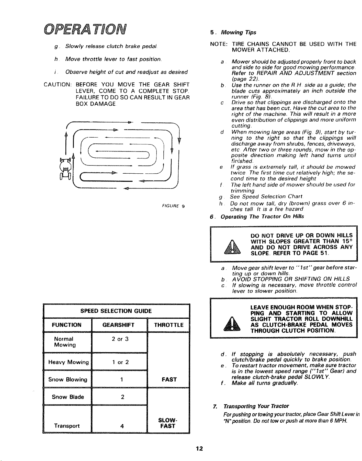
FIGURE 9
SPEED SELECTION GUIDE
FUNCTION GEARSHIFT THROTTLE
No_mal 2 or 3
Mowing
Heavy Mowing 1 or 2
Snow Blowing 1 FAST
Snow Blade 2
,,,i,,11,
SLOW-
Transport 4 FAST
5, Mowing Tips
NOTE: TIRE CHAINS CANNOT BE USED WITH THE
MOWER ATTACHED.
6.
a Mower should be adjusted properly front to back
and side to side for good mowing performance
Refer to REPAIR AND ADJUSTMENT section
(page 22)..
b. Use the runner on the R H side as a guide; the
blade cuts approximately an inch outside the
runner (Fig 8).
c Drive so that clippings are discharged onto the
area that has been cut. Have the cut area to the
right of the machine.. This will result in a more
even distribution of clippings and more uniform
cutting
d When mowing large areas (Fig 9), start by tur-
ning to the right so that the clippings will
discharge away from shrubs, fences, driveways,
etc After two or three rounds, mow in the op-
posite direction making teft hand turns unzit
finished.
e tf grass is extremely tall, it should be mowed
twice The first time cut relatively high; the se-
cond time to the desired height
f The left hand side of mower should be used for
trimming
g See Speed Selection Chart
h Do not mow tall, dry {brown) grass over 6 in-
ches tall It is a fire hazard
Operating The Tractor On Hills
DO NOT DRIVE UP OR DOWN HILLS
WITH SLOPES GREATER THAN 15 °
AND DO NOT DRIVE ACROSS ANY
SLOPE, REFER TO PAGE 5t,
..................... =1 i H...........
a Move gear shift lever to "' 1st" gear before star-
ting up or down hills.
b AVOID STOPPING OR SHIFTING ON HILLS
c If slowing is necessary, move throttle control
lever to slower position.
LEAVE ENOUGH ROOM WHEN STOP-
PING AND STARTING TO ALLOW
SLIGHT TRACTOR ROLL DOWNHILL
AS CLUTCH-BRAKE PEDAL MOVES
THROUGH CLUTCH POSITION,
, , i i1,,,111,, ,i, I
do If stopping is absolutely necessary, push
clutch/brake pedal quickly to brake position_
e . To restart tractor movement, make sure tractor
is in the lowest speed range ("1st" Gear) and
release clutch-brake pedal SLOWL Y.
f. Make all turns graduafly,
7. Transpotfing Your Tractor
For pushing or towingyour tractor, place Gear Shift Lever in
"N" position. Do not tow or push at more than 6 MPH.
12
To keep your tractor running better, longer, per-
form necessary service using the following
maintenance schedule:
With Every Mowing
1 Make sure alf nuts on bolts are tight and cotter pins
and retainer springs are secuke
2 Observe all safety precautions
3 Keep tractor well lubricated (refer to page 17)
BEFORE MAKING ANY INSPECTION,
ADJUSTMENT, OR REPAIR:
1. PUSH CLUTCH!BRAKE PEDAL COM-
PLETELY DOWN
2 MOVE'GEAR SHIFT CONTROL LEVER
TO NEUTRAL POSITION.
3, PLACE PARKING BRAKE IN "'ENGAG-
ED" POSITION° REMOVE FOOT FROM
PEDAL.
4r DISENGAGE ATTACHMENT CLUTCH
LEVER
5 SHUT OFF THE ENGINE
6 MAKE ABSOLUTELY SURE THE
BLADES AND ALL MOVING PARTS
HAVE COMPLETELY STOPPED.
7 DISCONNECT THE SPARK PLUG WIRE
FROM THE SPARK PLUG AND KEEP
WIRE AWAY FROM THE SPARK PLUG
TO PREVENT INJURY FROM ACCI"
DENTAL STARTING. BECAREFUL TO
AVOID TOUCHING HOT ENGINE OR
MUFFLER COMPONENTS_
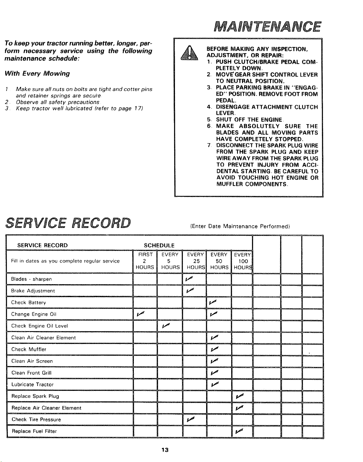
SERWCE RECORD
(Enter Date Maintenance Performed)
SERVICE RECORD SCHEDULE
FIRST EVERY EVERY EVERY EVERY
Fill in dates as you complete regular service 2 5 25 50 100
HOURS HOURS HOURS HOURS HOUR, {
Blades _ sharpen pJ
Brake Adjustment
Check Battery
........... :2"' ' ' 't_ "
Change Engine Oil _' _,J
Check Engine Oil Level
Clean Air Cleaner Element t_
, ,i ,
Check Muffler p_
Clean Air Screen V _"
Clean Front Grill V =e
,uu,,, i , ........
Lubricate Tractor p_'
Replace Spark Plug l_
nu,,ll,, i, i,u ........... :
Replace Air Cleaner Element pJ
-, ,u, ,.......
Check Tire Pressure
Replace Fuel Filter
13
ADJUSTMENT
JAM NUT
NUT A I
t U2
(WITH PARKING
BRAKE ENGAGED)
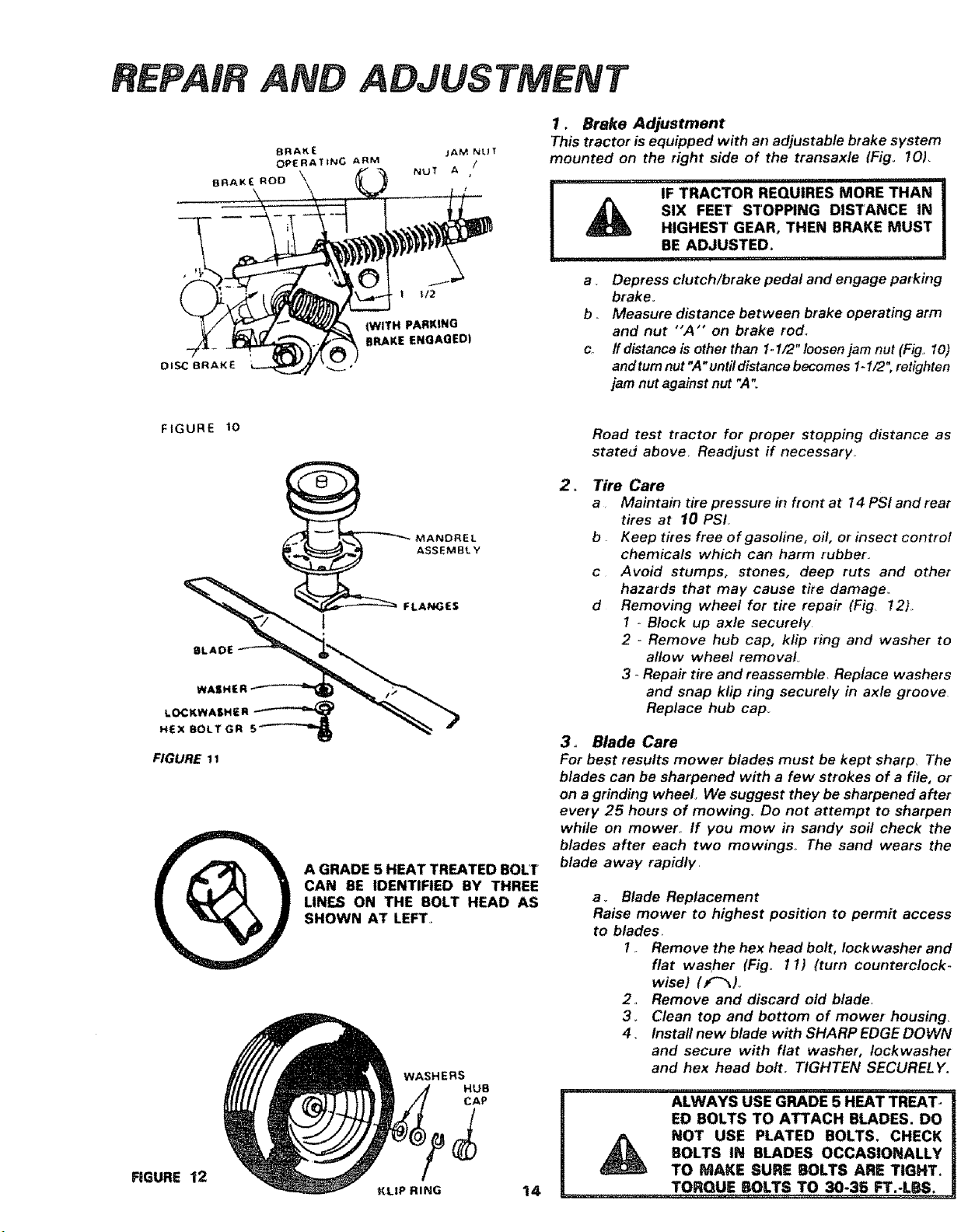
1. Brake Adjustment
This tractor is equipped with an adjustable brake system
mounted on the right side of the transaxle IFigo IOL
IF TRACTOR REQUIRES MORE THAN
SIX FEET STOPPING DISTANCE IN
HIGHEST GEAR, THEN BRAKE MUST
BE ADJUSTED_
,,111,,i,,,11,111 ii1,,,i,i
a . Depress clutch/brake pedal and engage parking
brake.
b .. Measure distance between brake operating arm
and nut "'A'" on brake rod_
c ffdistanceisotherthan 1-1/2"toosenjamnut(Fig.. 1o)
and tum nut "A"until distance becomes 1-I/2", retighten
jam nut against nut ",4"
FIGURE t0
FIGURE 12
ASSEMBLY
FLANGES
A GRADE 5 HEAT TREATED BOLT
CAN BE IDENTIFIED BY THREE
L|NF_ ON THE BOLT HEAD AS
SHOWN AT LEFT,
WASHERS
HUB
CAP
KLIP RING 14
Road test tractor for proper stopping distance as
stated above. Readjust if necessary..
= Tire Care
a Maintain tire pressure in front at 14 PSI and rear
tires at 10 PSI
b Keep tires free of gasoline, oil, or insect control
chemicals which can harm rubber.
c Avoid stumps, stones, deep ruts and other
hazards that may cause t#e damage.
d Removing wheel for tire repair (Fig !2).
1 - Block up axle securely
2 - Remove hub cap, klip ring and washer to
allow wheel removal
3 - Repair tire and reassemble. Replace washers
and snap klip ring securely in axle groove
Replace hub cap_
3, Blade Care
For best results mower blades must be kept sharp, The
blades can be sharpened with a few strokes of a file, or
on a grinding wheel, We suggest they be sharpened after
every 25 hours of mowing. Do not attempt to sharpen
while on mower,, If you mow in sandy soil check the
blades after each two mowings,, The sand wears the
blade away rapidly
a. Blade Replacement
Raise mower to highest position to permit access
to blades
I Remove the hex head bolt, lock washer and
flat washer (Fig° 11) (turn counterclock-
wise) (f'_).
2 Remove and discard old blade.
3 Clean top and bottom of mower housing.
4 Install new blade with SHARP EDGE DOWN
and secure with flat washer, Iockwasher
and hex head bolt. TIGHTEN SECURELY.
l ALWAYS USE GRADE 5 HEAT TREAT-
ED BOLTS TO ATTACH BLADES. DO
NOT USE PLATED BOLTS. CHECK
BOLTS IN BLADES OCCASIONALLY
ToMA ESUREBOLTSAReTmHT.
TORQUEBOLTSTOZ0-3B
b,
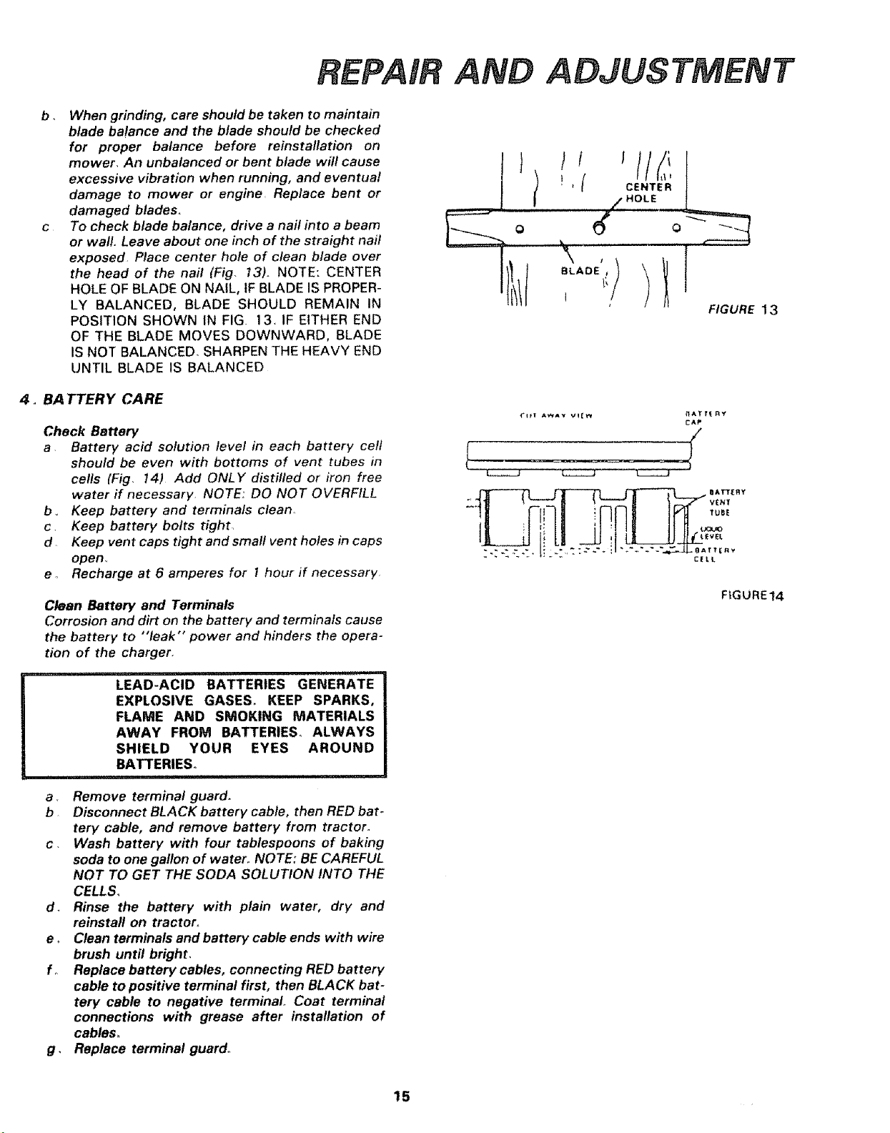
When grinding, care should be taken to maintain
blade balance and the blade should be checked
for proper balance before reinstallation on
mower, An unbalanced or bent blade will cause
excessive vibration when running, and eventual
damage to mower or engine Replace bent or
damaged blades.
To check blade balance, drive a nail into a beam
or wall. Leave about one inch of the straight nail
exposed. Place center hole of clean blade over
the head of the nail (Fig. 13). NOTE: CENTER
HOLE OF BLADE ON NAIL, tF BLADE IS PROPER-
LY BALANCED, BLADE SHOULD REMAIN IN
POSITION SHOWN IN FIG. 13. IF EITHER END
OF THE BLADE MOVES DOWNWARD, BLADE
IS NOT BALANCED. SHARPEN THE HEAVY END
UNTIL BLADE IS BALANCED
4. BA TTERY CARE
Check Battery
a Battery acid solution level in each battery celt
should be even with bottoms of vent tubes in
cells (Fig. 14) Add ONLY distilled or iron free
water if necessary NOTE: DO NOT OVERFILL
b .. Keep battery and terminals clean.
c. Keep battery bolts tight.
d Keep vent caps tight and small vent holes in caps
open.
e o Recharge at 6 amperes for 1 hour if necessary
Clean Battery and Terminals
Corrosion and dirt on the battery and terminals cause
the battery to "leak" power and hinders the opera-
tion of the charger.
LEAD-ACID BATTERIES GENERATE
EXPLOSIVE GASES° KEEP SPARKS,
FLAME AND SMOKING MATERIALS
AWAY FROM BATTERIES° ALWAYS
SHIELD YOUR EYES AROUND
BATTERIES°
a Remove terminal guard.
b Disconnect BLACK battery cable, then RED bat-
tery cable, and remove battery from tractor.
c. Wash battery with four tablespoons of baking
soda to one gallon of water, NOTE: BE CAREFUL
NOT TO GET THE SODA SOLUTION INTO THE
CELLS,
d. Rinse the battery with plain water, dry and
reinstafl on tractor°
e, Clean terminals and battery cable ends with wire
brush until bright,
f, Replace battery cables, connecting RED battery
cable to positive terminal first, then BLACK bat-
tery cable to negative terminal,. Coat terminal
connections with grease after installation of
cables.
g, Replace terminal guard,,
AND ADJUSTMENT
I
t ,i/LI
t ! , { CE.TE.
/_ HOLE
o
FIGURE 13
{'lit A'P,_AY V_[_ ftA[Itl_Ry
CAP
FIGURE14
15
AN{) ADJUSTMENT
•F \\
-20 ° 0 °
32 ° 60 ° 80 ° 100 °
I il 11
30 or 10W-30
/
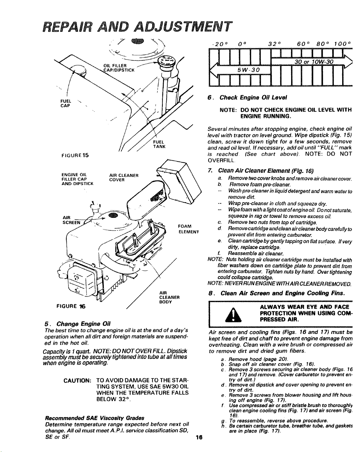
6. Check Engine Oil Level
NOTE: DO NOT CHECK ENGINE OIL LEVEL WITH
ENGINE RUNNING.
FIGURE 15
TANK
Several minutes after stopping eng#_e, check engine oil
level with tractor on level ground° Wipe dipstick (Fig. 15)
clean, screw it down tight for a few seconds, remove
and read oil level If necessary, add oil until "'FULL" mark
is reached. (See chart aboveL NOTE: DO NOT
OVERFILL
ENGINE OIL AIR CLEANER
FILLER CAP COVER
AND DIPSTICK
AIR
SCREEN
FOAM
ELEMENT
FIGURE 16
R
5. Change Engine Oil
The best time to change engine oilisat the end of a day's
operation when all dirt and foreign materials are suspend-
ed in the hot oil
Capacity is 1quart. NOTE: DO NOT OVER FILL. Dipstick
assembly must be securely tightened into tube at afttimes
when engine is operating,
CAUTION: TO AVOID DAMAGE TO THE STAR-
TING SYSTEM, USE SAE 5W30 OIL
WHEN THE TEMPERATURE FALLS
BELOW 32 ° .
Recommended SAE Viscosity Grades
Determine temperature range expected before next oil
change. All oil must meet A,P,L service classification SD,
SE or SF,
16
7, Clean Air Cleaner Element (Fig. 16)
a,. Remove two cover knobs and remove air cleaner cover,
b, Remove foam pre-cleaner,,
-- Wash pre_cleaner in liquid detergent and warm water to
remove dirt.
-- Wrap pre-cleaner in cloth and squeeze dry_
-- Wipe foam with a light coat of engine oil, Do not saturate,
squeeze in rag or towel to remove excess oil,.
co Remove two nuts from top of cartridge.
d, Remove cartridge and clean air cleaner body carefully to
prevent dirt from entering carburetor,
e, Clean cartridge by gently tapping on flat surface, ff very
dirty, replace cartridge_
f. Reassemble air cleaner.
NOTE:" Nuts holding a# cleaner cartridge must be installed with
fiber washers down on cartridge plate to prevent dirt from
ontering carburetoro TIghten nuts by hando Overtightening
could collapse cartridge.
NOTE: NEVER RUN ENGINE WITH AIR CLEANER REMOVED,
8o Clean Air Screen and Engine Cooling Fins.
i _ ALWAYS WEAR EYE AND FACE
PROTECTION WHEN USING COM-
PRESSED AIR.
Air screen and cooling fins (Figs° 16 and 17) must be
kept free of dirt and chaff to prevent engine damage from
overheating, Clean with a wire brush or compressed air
to remove dirt and dried gum fibers°
a,, Remove hood (page 201,.
b, Snap off air cleaner cover (Fig. 16).
c, Remove 3 screws securing air cleaner body tFigso 16
and 17) and remove, (Cover carburetor to prevent en-
try of dirt,)
d . Remove oll dipstick and cover opening to prevent an,.
try of dirt.
e_ Remove 3 screws from blower housing and lift hous-
ing off engine (Fig, 17).
f Use compressed air or stiff bristle brush to thoroughly
clean engine cooling fins {Fig° 17) and air screen {Fig_
16),
g, To reassemble, reverse above procedure_
h . Be certain carburetor tube, breather tube, and geskat5
are in place (Fig, 171,
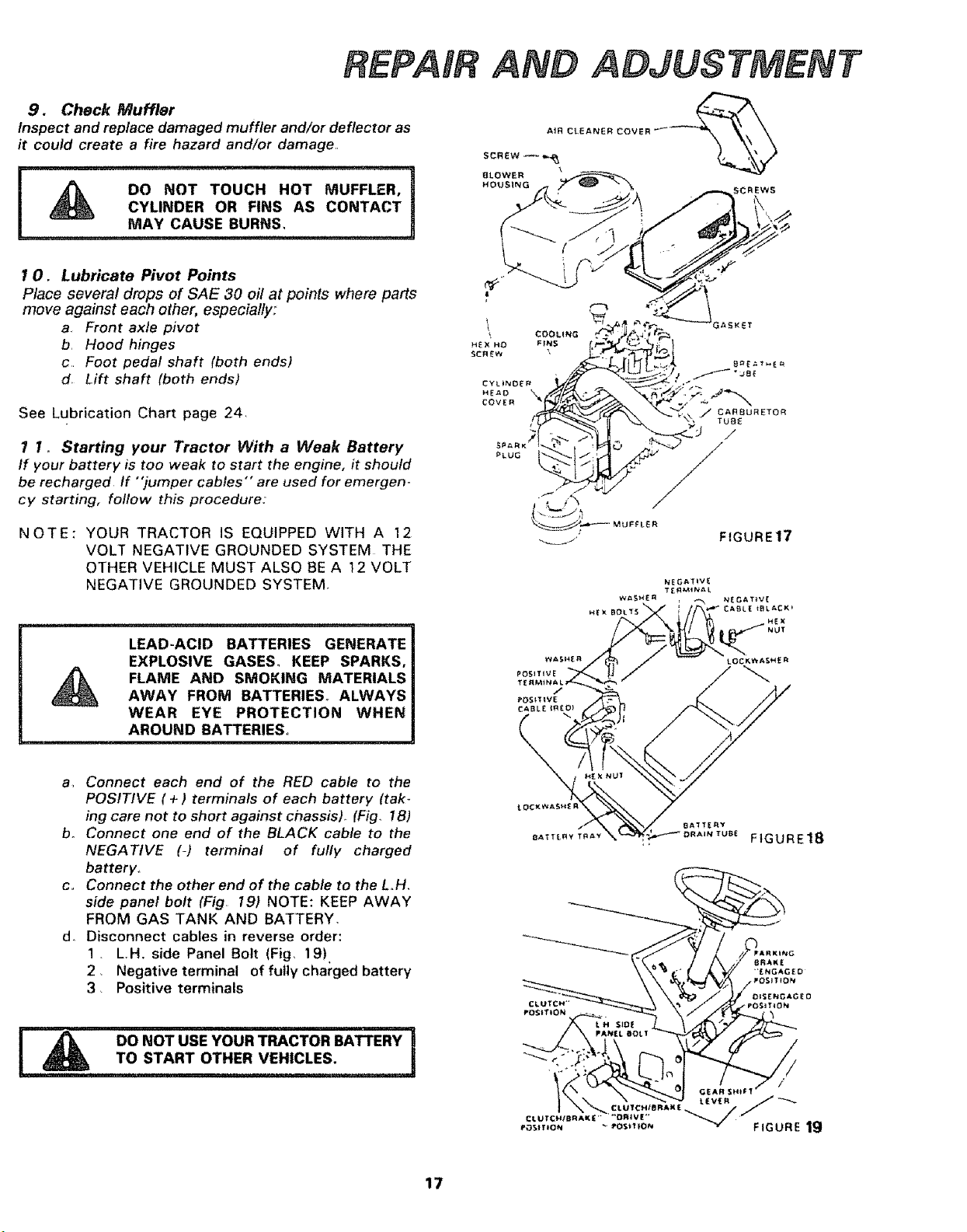
9. CheckMuffler
Inspectandreplacedamagedmufflerand/or deflector as
it could create a fire hazard and/or damage,=
!
DO NOT TOUCH HOT MUFFLER,
CYLINDER OR FINS AS CONTACT]
................................................MAY CAUSE BURN s, H
AND ADJUSTMENT
:REWS
I O. Lubricate Pivot Points
Place several drops of SAE 30 oil at points where parts
move against each other, especially,:'
a. Front axle pivot
b, Hood hinges
c Foot pedal shaft (both ends)
d_ Lift shaft (both ends)
See Lubrication Chart page 24
1 1, Starting your Tractor With a Weak Battery
If your battery is too weak to start the engine, it should
be recharged If "'jumper cables'" are used for emergem
cy starting, follow this procedure:
NOTE: YOUR TRACTOR IS EQUIPPED WITH A 12
VOLT NEGATIVE GROUNDED SYSTEM THE
OTHER VEHICLE MUST ALSO BE A 12 VOLT
NEGATIVE GROUNDED SYSTEM,
LEAD-ACID BATTERIES GENERATE
EXPLOSIVE GASES, KEEP SPARKS,
FLAME AND SMOKING MATERIALS
AWAY FROM BATTERIES° ALWAYS
WEAR EYE PROTECTION WHEN
AROUND BATTERIES,
a, Connect each end of the RED cable to the
POSITIVE (+) terminals of each battery (tak-
ing care not to short against chassis). (Fig. 18)
b. Connect one end of the BLACK cable to the
NEGATIVE (-) terminal of fully charged
battery°
c,, Connect the other end of the cable to the LH,
side panel bolt (Fig, 19) NOTE: KEEP AWAY
FROM GAS TANK AND BATTERY.
d. Disconnect cables in reverse order:
1, L H, side Panel Bolt (Fig, 19)
2, Negative terminal of fully charged battery
3, Positive terminals
F_W DO NOT USE YOUR TRACTOR BATTERY
TO START OTHER VEHICLES.
, , i i , i i i
17
ADJUSTMENT
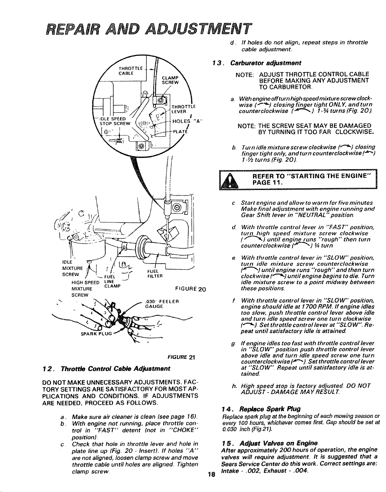
d. If holes do not align, repeat steps in throttle
cable adjustment_
13.
Carburetor adjustment
NOTE: ADJUST THROTTLE CONTROL CABLE
BEFORE MAKING ANY ADJUSTMENT
TO CARBURETOR,,
THROTTLE
LEVER
!
HOLES "A"
With engine off turn high speed mixture screw clock-
wise ("-'_) closing finger tight ONLY, and turn
counterclock wise (_-_ ) 1.3._ turns (Fig. 20).
NOTE; THE SCREW SEAT MAY BE DAMAGED
BY TURNING IT TOO FAR CLOCKWISE.
MIXTURE [
SCREW --- _9
HIG.SPEEDU.E
CLAMP
MIXTURE
SCREW
FUEL
FILTER
FIGURE 20
.030" FEELER
GAUGE
SPARK PLUG
FIGURE 2t
12. Throttle Control Cable Adjustment
DO NOT MAKE UNNECESSARY ADJUSTMENTS, FAC-
TORY SETTINGS ARE SATISFACTORY FOR MOST AP-
PLICATIONS AND CONDITIONS. IF ADJUSTMENTS
ARE NEEDED, PROCEED AS FOLLOWS.
a o Make sure air cleaner is clean (see page 16),
b, With engine not running, place throttle con-
trol in "FAST" detent (not in "CHOKE"
position),
c Check that hole in throttle lever and hole in
plate line up (Fig_ 20 _ Insert). tf holes "A'"
are not aligned, loosen clamp screw and move
throttle cable until holes are aligned, Tighten
clamp screw.
b,
e
g
h,
Turn idle mixture screw clockwise ("-_) closing
finger tight only, and tutn counterclockwise (_'_)
1-½ turns (Fig, 20)
i i,,i .... i,i
REFER TO "STARTING 'THE ENGINE"
II
PAGE 11 .,,
i
..................... i
Start engine and allow to warm for five minutes.
Make final adjustment with engine running and
Gear Shift lever in "'NEUTRAL" position
With throttle control lever in "FAST" position,
turnnhigh speed mixture screw clockwise
( f _ ) until engine runs "rough" then turn
counterclockwise ('_"_) _ turn
With throttle control lever in "SL O W" position,
turn idle mixture screw counterclockwise
(_"_) until engine runs "rough" and then turn
clockwise ("-'_) until engine begins to die. Turn
idle mixture screw to a point midway between
these positions,
With throttle control lever in "SLOW" position,
engine should idle at 1700 RPMo ff engine idles
too slow, push throttle control lever above idle
and turn idle speed screw one turn clockwise
("'_). Set throttle controllever at "SL OW'_ Re.
peat until satisfactory idle is attained
ff engine idles too fast with throttle control lever
in "SLOW" position push throttle control lever
above idle and turn idle speed screw one turn
counterclockwise (._t Set throttle control/ever
at *'SLOW". Repeat until satisfactory idle is at-
tained
High speed stop is factory adjusted, DO NOT
ADJUST - DAMAGE MAY RESULT
18
1 4, Replace Spark Plug
Replace spark plug at the beginning of each mowing season or
every 100 hours, whichever comes firsL Gap should be sot at
0.030 inch (Fig21).
1 5. Adjust V_dvee on Engine
After approximately 200 hours of operation, the engine
valves will require adjustment, It is suggested that a
Sears Service Center do this work° Correct settings are:
Intake - _002, Exhaust- o004_
ADJUSTMENT
! _ BE SURE THERE ARE""NO FUEL 'LINE !
LEAKS AND THAT HOSE CLAMPS ARE
!
• PROPERLY INSTALLED° ,................
16o Replace In-Line Fuel Filter
If fuel filter is clogged, obstructing fuel flow to car-
buretor, replacement is required.
ao With engine cool, remove filter and plug fuel line
sections which were removed fromboth ends offuelfilter
(Fig. 20)_
b. Place new fuel filter in position in fuel line
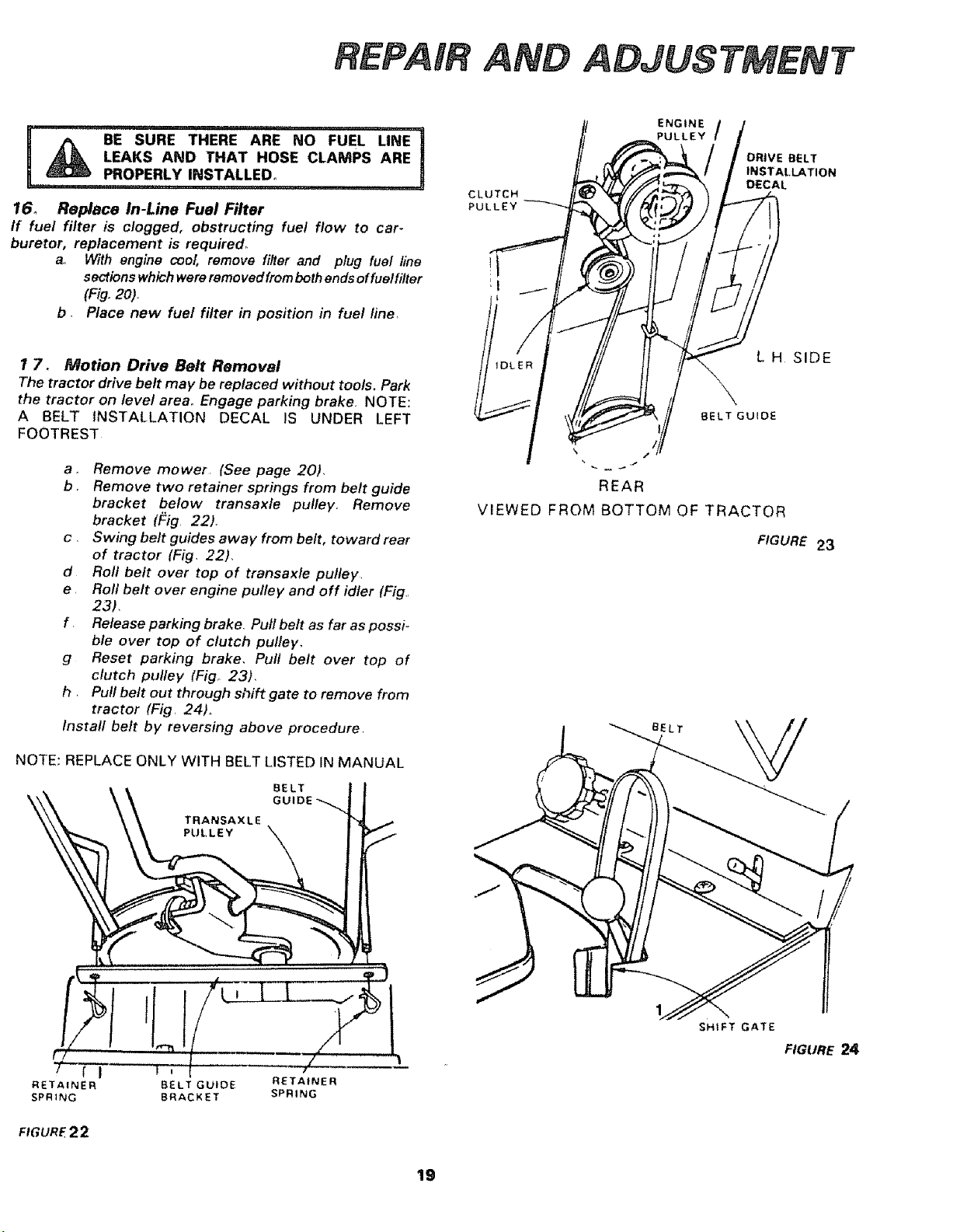
T 7. Motion Drive Belt Removal
The tractor drive belt may be replaced without tools. Park
the tractor on level area, Engage parking brake. NOTE:
A BELT INSTALLATION DECAL IS UNDER LEFT
FOOTREST
a_ Remove mower, (See page 20),
b, Remove two retainer springs from belt guide
bracket below transaxle pulley_ Remove
bracket (Fig 22).
c, Swing belt guides away from belt, toward rear
of tractor (Fig, 22),
d Roll belt over top of transaxte pulley.
e Roll belt over engine pulley and off idler (Fig.,
23).
f Release parking brake, Pull belt as far as possi-
ble over top of clutch pulley,
g Reset parking brake_ Pull belt over top of
clutch pulley (Fig° 23),
h, Pull belt out through shift gate to remove from
tractor (Fig, 24)°
Install belt by reversing above procedure
NOTE: REPLACE ONLY WITH BELT LISTED IN MANUAL
t, BELT
\\ oo,oE-..
\ TRANSAXLE
7 f I •
RETAINER BELT GUIDE RETAINER
SPR1NG BRACKET SPRING
FIGURE2 2
CLUTCH
PULLEY
ENGINE
PULLEY /
DRIVE BELT
INSTALLATION
DECAL
L H SIDE
BELT GUIDE
REAR
VIEWED FROM BOTTOM OF TRACTOR
FIGURE 23
BELT
SHIFT GATE
FIGURE 24
19
ADJUSTMENT
\
18. Fuse Replacement
Replace with 30 amp automotive - type plug-in fuse, The
fuse holder is located under the dash.
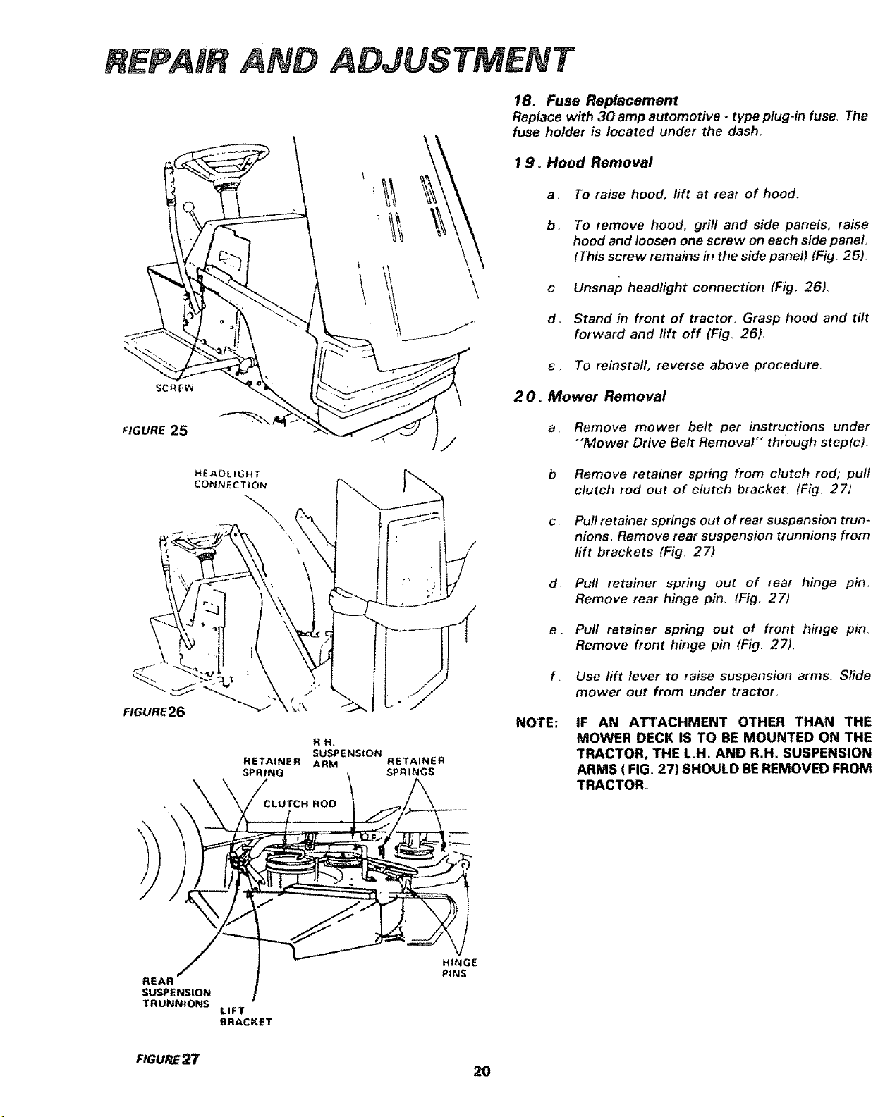
1 9o Hood Removal
a, To raise hood, lift at rear of hood.
b_
C
To remove hood, grill and side panels, raise
hood and loosen one screw on each side panel.
(This screw remains in the side panel) (Fig,, 25),
Unsnap headlight connection (Fig. 26)_
d_ Stand in front of tractor, Grasp hood and tilt
forward and lift off (Fig 26),
SCREW
e • To reinstall, reverse above procedure_
2 O. Mower Removal
FIGURE25
a Remove mower belt per instructions under
"'Mower Drive Belt Removal" through step(c)
HEAOLIGHT
CONNECTION
\
\
b, Remove retainer spring from clutch rod; pull
clutch rod out of clutch bracket. (Fig 27)
c Pull retainer springs out of rear suspension trun-
nions, Remove rear suspension trunnions from
lift brackets (Fig° 27),
d, Pull retainer spring out of rear hinge pin,
Remove rear hinge pin, (Fig_ 27)
FIGURE26 _,'k
RH.
SUSPENSION
RETAINER ARM RETAINER
SPRING t SPRINGS
REAR/ ] - .,,N.#E
SUSPENSION ]
TRUNNIONS
LIFT
BRACKET
NOTE:
e, Pull retainer spring out of front hinge pin_
Remove front hinge pin (Fig, 27),
f. Use lift lever to raise suspension arms, Slide
mower out from under tractor,
IF AN ATTACHMENT OTHER THAN THE
MOWER DECK IS TO BE MOUNTED ON THE
TRACTOR, THE LH. AND R.H. SUSPENSION
ARMS ( FIGo27) SHOULD BEREMOVED FROM
TRACTOR_
FnGURE27
20
AND ADJUSTMENT
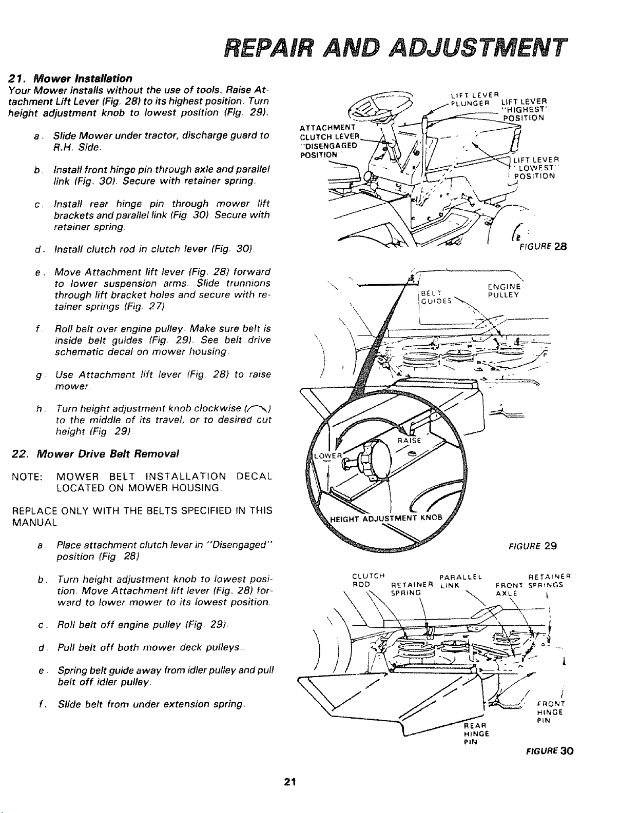
21. Mower Installation
Your Mower installs without the use of tools, Raise At _
tachment Lift Lever (Fig. 28) to its highest position. Turn
height adjustment knob to lowest position (Fig. 29).
a. Slide Mower under tractor, discharge guard to
R.H. Side.
b, Install front hinge pin through axle and parallel
link (Fig, 30). Secure with retainer spring
c, Install rear hinge pin through mower rift
brackets and parallel link (Fig 30) Secure with
retainer spring,
d. Install clutch rod in clutch lever (Fig. 30)-
e , Move Attachment lift lever (Fig, 28) forward
to lower suspension arms, Slide trunnions
through lift bracket holes and secure with re-
tainer springs (Fig,. 27)
f Roll belt over engine pulley. Make sure belt is
inside belt guides (Fig 29). See belt drive
schematic decal on mower housing
g. Use Attachment lift lever (Fig. 28) to raise
mower
h . Turn height adjustment knob clockwise (F'_)
to the middle of its travel, or to desired cut
height (Fig, 29)_
22. Mower Drive Belt Removal
NOTE: MOWER BELT INSTALLATION DECAL
LOCATED ON MOWER HOUSING.
REPLACE ONLY WITH THE BELTS SPECIFIED IN THIS
MANUAL
a • Place attachment clutch lever in "Disengaged"
position (Fig 28)
b Turn height adjustment knob to lowest posi-
tion. Move Attachment lift lever (Fig° 28) for-
ward to lower mower to its lowest position,
c Roll belt off engine pulley (Fig, 29),
d. Pull belt off both mower deck pulleys.,
e • Spring belt guide away from idler pulley and pull
belt off idler pulley.
f. Slide belt from under extension spring,
ATTACHMENT
CLUTCH LEVER
"'DISENGAGED
POSITION"
\
CLUTCH
ROD
LtFT LEVER
UNGER LiFT LEVER
"HIGHEST'
POSiTiON
LiFT LEVER
LOWEST'
I POSITION
ENGINE
PULLEY
FIGURE 29
FIGURE30
21
ADJUSTMENT
ENGINE
PULt_EY
BELT _ IOLER
IDLER BELT
,GUIDE
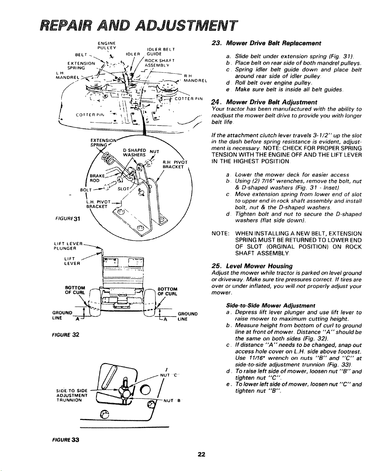
23. Mower Drive Belt Replacement
ao Slide belt under ex tension spring (Fig. 31)
b. Place belt on rear side of both mandrel pulleys..
c. Spring idler belt guide down and place belt
around rear side of idler pulley
d Roll belt over engine pulley..
e Make sure belt is inside all belt guides
24, Mower Drive Belt Adjustment
Your tractor has been manufactured with the abifity to
readjust the mower belt drive to provide you with longer
belt life.
FIGURE 31
R=H _VOT
BRACKET \
If the attachment clutch lever travels 3-1/2" up the slot
in the dash before spring resistance is evident, adjust-
ment is necessary, NOTE: CHECK FOR PROPER SPRING
TENSION WITH THE ENGINE OFF AND THE LIFT LEVER
IN THE HIGHEST POSITION
a Lower the mower deck for easier access
b Using (2) 7/16" wrenches, remove the bolt, nut
& D-shaped washers (Fig° 31 _ Inset)
c Move extension spring from lower end of slot
to upper end in rock shaft assembly and install
bolt, nut & the D-shaped washers,
d Tighten bolt and nut to secure the D-shaped
washers (flat side down).
LIFT LEVER_
PLUNGER _"1_
LIFT
LEVER
BOTTOM ...,_.,
OF CURL f
GROUND_ "_"
LINE A_I. T_-
FIGURE 32
SIDE TO SiDE
ADJUSTMENT
TRUNNION
8OTTOM
URL
.O0N0
NOTE:
WHEN INSTALLING A NEW BELT, EXTENSION
SPRING MUST BE RETURNED TO LOWER END
OF SLOT (ORGtNAL POSITION) ON ROCK
SHAFT ASSEMBLY,
25. Level Mower Housing
Adjust the mower while tractor is parked on level ground
or driveway. Make sure tire pressures correct if t#es are
over or under inflated, you will not properly adjust your
mower_
Side.to-Side Mower Adjustment
a. Depress lift lever plunger and use rift lever to
raise mower to maximum cutting height.
b. Measure height from bottom of curl to ground
line at front of mower_ Distance "A " should be
the same on both sides (Fig, 32).
c, If distance "'A '" needs to be changed, snap out
access hole cover on L.H_ side above footrest.
Use 11/16" wrench on nuts "'B" and "'C" at
side-to-side adjustment trunnion (Fig. 33)
d_ To raise left side of mower, loosen nut "'B'" and
tighten nut "C',
e_ To lower left side of mower, loosen nut "'C'" and
tighten nut "'B".
FIGURE 33
22
ADJUSTMENT
NOTE: ONE ROTATION OF ADJUSTMENT NUTS IS
EQUIVALENT TO APPROXIMATELY 3/16"
HEIGHT CHANGEr
f. Be sure all nuts are securely tightened
g ,, Replace cover,
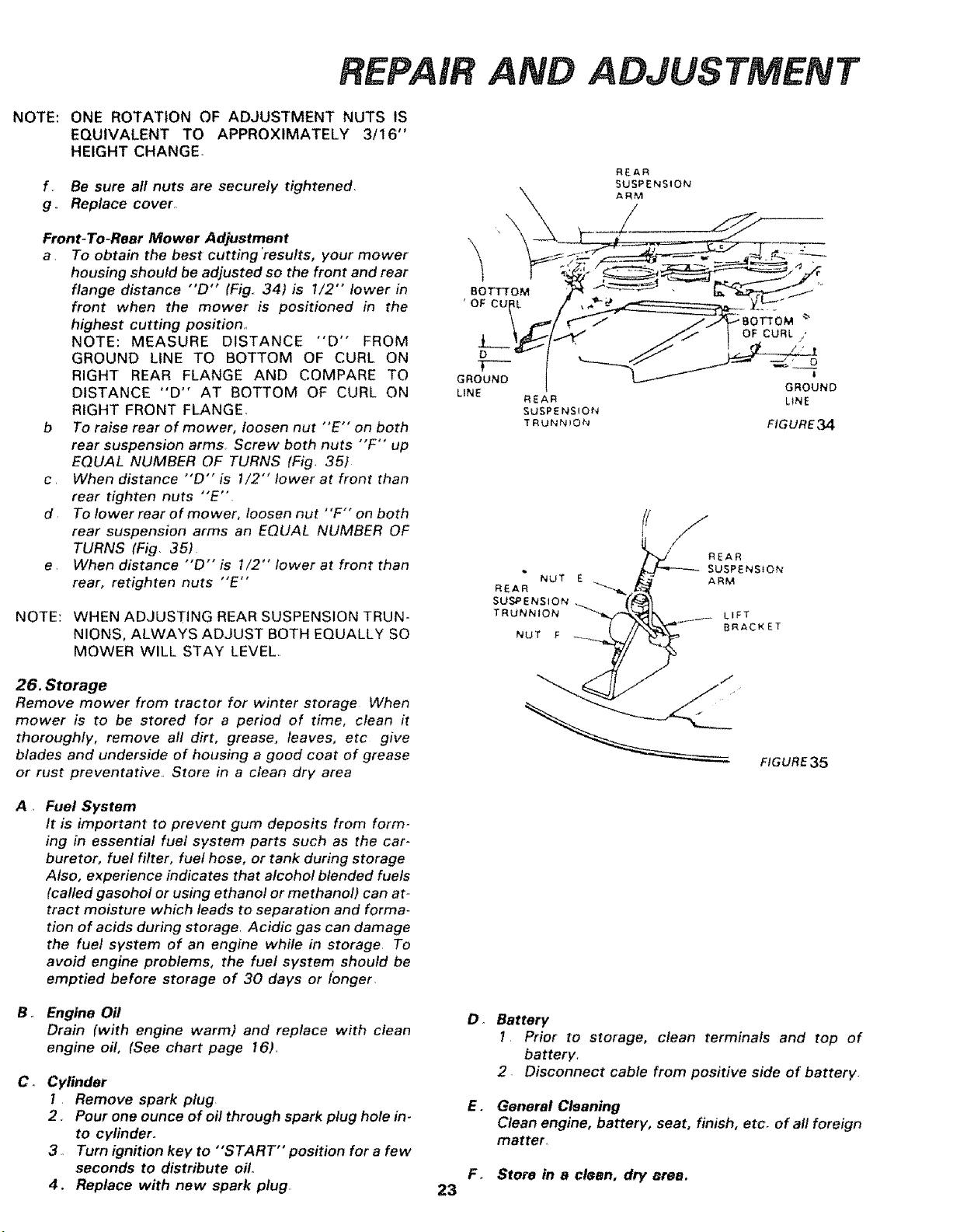
Front-To-Rear Mower Adjustment
a To obtain the best cutting "results, your mower
housing should be adjusted so the front and rear
flange distance "'D'" (Fig.. 34) is 1/2" lower in
front when the mower is positioned in the
highest cutting position.,
NOTE: MEASURE DISTANCE "'D'" FROM
GROUND LINE TO BOTTOM OF CURL ON
RIGHT REAR FLANGE AND COMPARE TO
DISTANCE "'D'" AT BOTTOM OF CURL ON
RIGHT FRONT FLANGE,
b To raise rear of mower, loosen nut "E'" on both
rear suspension arms Screw both nuts "'F'" up
EQUAL NUMBER OF TURNS (Fig. 35)
c. When distance "'D" is 1/2" lower at front than
rear tighten nuts "E'"
d To lower rear of mower, loosen nut "F'" on both
rear suspension arms an EQUAL NUMBER OF
TURNS (Fig. 35)
e. When distance "'D" is 1/2" lower at front than
rear, retighten nuts "E'"
NOTE: WHEN ADJUSTING REAR SUSPENSION TRUN-
NIONS, ALWAYS ADJUST BOTH EQUALLY SO
MOWER WILL STAY LEVEL..
LINE
REAR
SUSPENSION
TRUNNION
NuT E
REAR
SUSPENSION
TRUNNION
NUT F
REAR
SUSPENSION
GROUND
LiNE
FIGURE 34
_/R E A R i
SUSPENS ON
ARM
LEFT
BRACKET
26. Storage
Remove mower from tractor for winter storage When
mower is to be stored for a period of time, dean it
thoroughly, remove a// dirt, grease, leaves, etc give
blades and underside of housing a good coat of grease
or rust preventative.. Store in a clean dry area
A • Fuel System
It is important to prevent gum deposits from form-
ing in essential fuel system parts such as the car-
buretor, fuel filter, fuel hose, or tank during storage
Also, experience indicates that alcohol blended fuels
(called gasohol or using ethanol or methanol) can at-
tract moisture which leads to separation and forma-
tion of acids during storage Acidic gas can damage
the fuel system of an engine while in storage. To
avoid engine problems, the fuel system should be
emptied before storage of 30 days or longer
B. Engine Oil
Drain (with engine warm) and replace with clean
engine oil, (See chart page 16),
C.
Cylinder
1 Remove spark plug
2. Pour one ounce of oil through spark plug hole in-
to cylinder.
3. Turn ignition key to "'START" position for a few
seconds to distribute oil.
4, Replace with new spark plug.
23
FIGURE35
Do Battery
1 Prior to storage, clean terminals and top of
battery.
2. Disconnect cable from positive side of battery
E. General Cleaning
Clean engine, battery, seat, finish, etc. of all foreign
matter
F. Store in a clean, dry area,
ADJUSTMENT
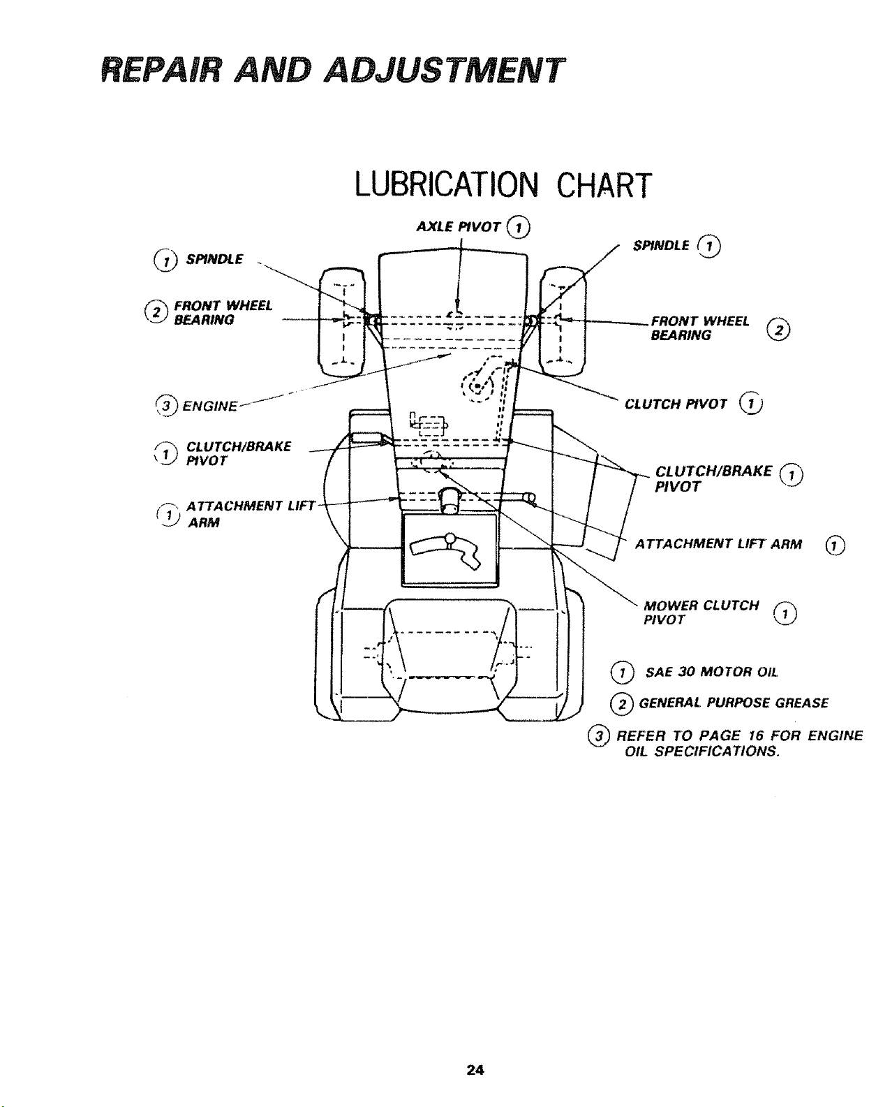
___ SPINDLE
LUBRICATION
AXLE PIVOT Q
CHART
SPINDLE ('_
( 2_ FRONT WHEEL
BEARING
WHEEL
BEARING (_
( 3"3"3_ENGINE ._
F_ CLUTCH/BRAKE
PIVOT
(_j ATTACHMENT LIFT"
ARM
CLUTCH PIVOT
CLUTCH/BRAKE _'_
PIVOT
A TTACHMENT LIFT ARM 1_
MOWER CLUTCH
PIVOT
(_ SAE 30 MOTOR OIL
(_ GENERAL PURPOSE GREASE
(_ REFER TO PAGE I6 FOR ENGINE
OIL SPECIFICATIONS.
24
TROUBLESHOOTING
WILL NOT START
WILL NOT TURN OVER
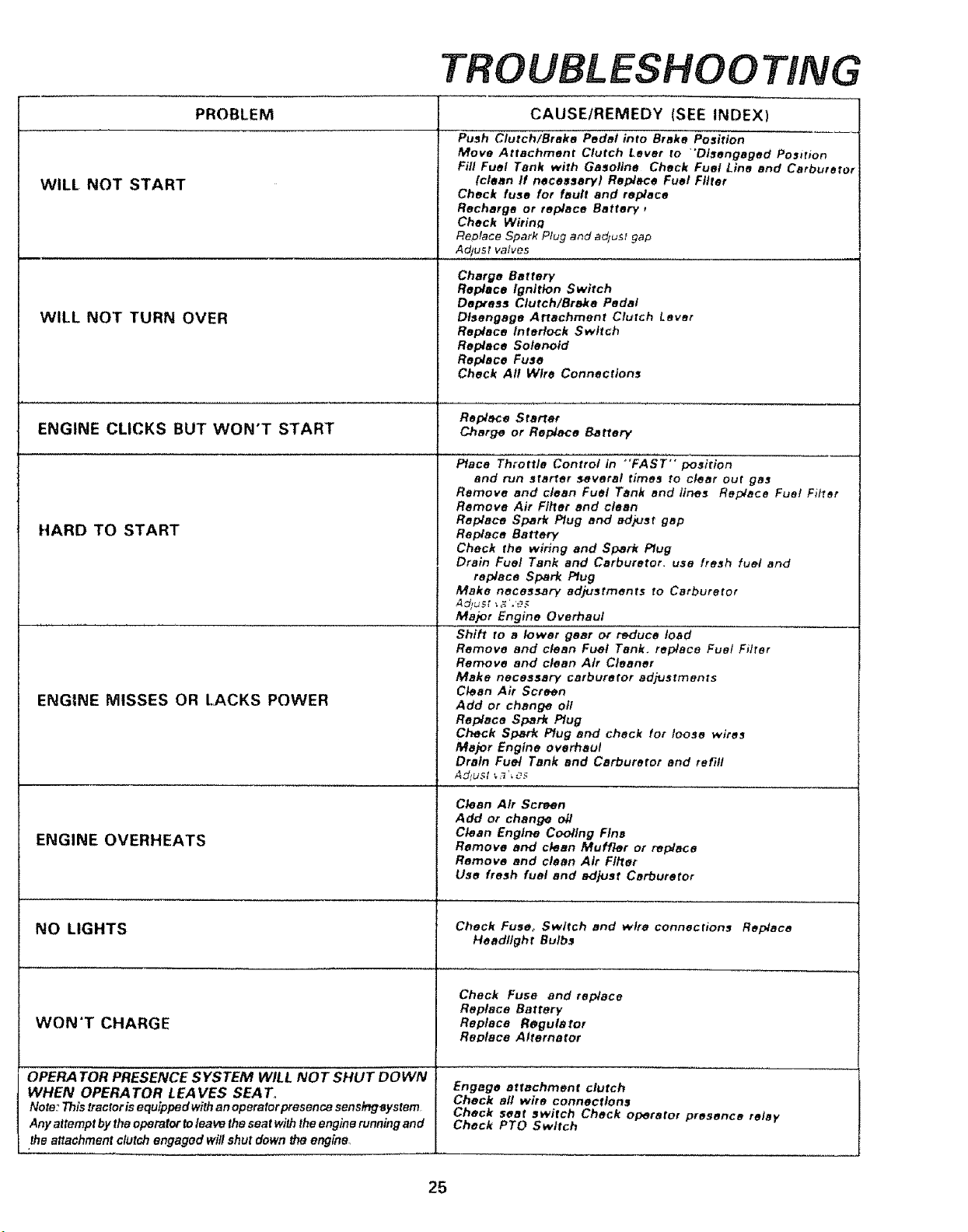
PROBLEM CAUSE/REMEDY (SEE INDEX)
Push Clutch/Brake Pedal into Brake Position
Move Attachment Clutch Lever to "'Disengaged Po_irion
Fill Fuel Tank with Gasoline Check Fuel Line and Carbuterot
(clean If necest_ary) Replace Fuel Filter
Check fuse for fault and replace
Recharge or replace Battery,
Check Wirin_
Re, lace Spark Plug and adjust gap
Adtusl valves
Charge Battery
Replace ignition Switch
Depress Clutch/Brake Pedal
Disengage Attachment Clutch Lever
Replace InteHock Switch
Replace Solenoid
Replace Fuse
Check All Wire Connections
Replace Starter
ENGINE CLICKS BUT WON'T START Cher_ or ReplaceBaHery
HARD TO START
ENGINE MISSES OR LACKS POWER
ENGINE OVERHEATS
NO LIGHTS
WON'T CHARGE
OPERA TOR PRESENCE SYSTEM WILL NOT SHUT DOWN
WHEN OPERA TOR LEA VES SEA T_
Note: This tractor isequipped with an operator presence sensing_ystem
Any attempt by the operator to lea ve the seat with the engine running and
the attachment clutch engaged will shut down the engine,
Place Throttle Control in "FAST" position
and run starter several times to clear out gas
Remove and clean Fuel Tank end llrms Replace Fuel Filter
Remove Air Flkter and clean
Replace Spark Plug end ad?Jet gap
Replace Barter/
Check the wiring and Spark Plug
Drain Fuel Tank and Carburetor. usa fresh fuel end
replace Spark Plug
Make necessary adjustments to Carburetor
Major Engine Overhaul
Shift re a lower gear or reduce load
Remove and clean Fuel Tank, replace Fue! Filter
Remove and clean Air Cleaner
Make necessary carburetor adjustments
Clean Air Screen
Add or change oi/
Replace Spark Plug
Check Spark Plug and check for loose wire_
Major Engine overhaul
Drain Fuel Tank and Carburetor and refill
Clean Air Screen
Add or change oil
Clean Engtrm Cooling Fins
Remove and clean Muffler or r_place
Remove and clean Air Fitter
Use fresh fuel and adjust Carburetor
Check Fuse_ Switch end wire connections Replace
Headlight Bulbs
Check Fuse and replace
Replace Battery
Replace Regulator
RaDtece Alternator
Engage attachment clutch
Check aft wire connections
Check seat switch Check operator presence relay
Check PTO Switch
25
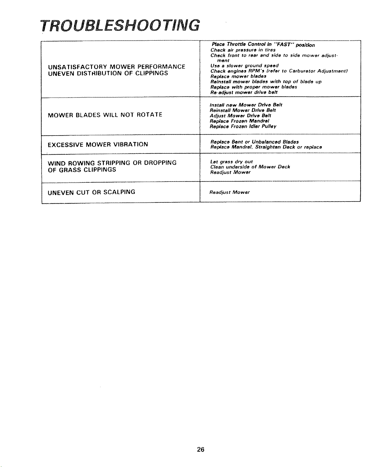
TROUBLESHOOTING
UNSATISFACTORY MOWER PERFORMANCE
UNEVEN DISTRIBUTION OF CLIPPINGS
MOWER BLADES WILL NOT ROTATE
Place Throttle Control In "'FAST'* posith)n
Check air pressure in fires
Check front to rear and _ide to side mower adjust
merit
Use a slower ground speed
Check engines RPM's (refer to Carburetor Adjustment}
Replace mower blades
Reinstall mower btadea with top of blade up
Replace with p_oper mower blades
Readjust mower drive belt
Instafl new Mower Drive Belt
Reinsfafl Mower Drive Belt
Adjust Mower Drive Belt
Replace Frozen Mandrel
Replace Frozen Idler Pulley
Replace Bent or Unbalanced Blades
EXCESSIVE MOWER VIBRATION Replace Mandrel_ Straighten Deck or replace
WIND ROWING STRIPPING OR DROPPING
OF GRASS CLIPPINGS
UNEVEN CUT OR SCALPING
Let grass dry out
Clean underside of Mower Deck
Readjust Mower
Readjust Mower
26