Loading ...
Loading ...
Loading ...

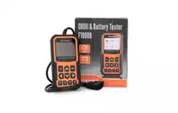
Foxwell F1000B OBDII&Battery Tester User’s Guide_ English Version_V1.00
9
J. One Click I/M Readiness Key -quick checks state emissions readiness and drive cycle
verification.
K. BACK Key - cancels an action and returns to previous screen or level.
L. ENTER Key - confirms an action or movement and moves to next level.
M. HELP Key- accesses to the Help function and it is also used to update the OBDII&Battery
tester when long pressed.
N. ERASE Key - accesses to erase fault code.
O. DTC key- accesses to read diagnostic fault code.
P. USB Port – provides a USB connection between the OBDII&Battery tester and PC or laptop.
Q. BATTERY Clip –connect battery clips to device to perform battery testing function.
2.2 Accessory Descriptions
This section lists the accessories that go with the OBDII&Battery tester. If you find any of the
following items missing from your package, contact your local dealer for assistance.
1 User’s Manual - provides operation instructions for the usage of the OBDII&Battery tester.
2.Batter Clips- connect battery clips to device to perform battery testing function
3 USB Cable- provides connection between the OBDII&Battery tester and a computer to upgrade
the tool.
4 Quick Start Guide– includes the user’s manual, NT Wonder update software and update files.
2.3 Technical Specifications
Display: 2.8”TFT color display
Working Temperature: 0 to 60 ℃ (32 to 140℉)
Storage Temperature: -20 to 70℃ (-4 to 158℉)
Power Supply: 8-18V vehicle power
Supported Protocols:J1850PWM, J1850-VPW, ISO9141, KWP2000 (ISO 14230), and CAN
(Control Area Network ISO 11898)
Dimensions (L*W*H): 172*97.5*32mm
Weight: 0.6kg
3 Getting Started
This section describes how to provide power to the OBDII&Battery tester, provides brief
introductions of applications loaded on the OBDII&Battery tester and display screen layout and
illustrates how to input text and numbers with the OBDII&Battery tester.
3.1 Providing Power to OBDII&Battery Tester
Before using the OBDII&Battery tester, make sure to provide power to the OBDII&Battery tester.
The unit operates on any of the following sources:
●
12-volt vehicle power
●
USB connection to personal computer.
3.1.1 Connecting to Vehicle Power
The OBDII&Battery tester normally powers on whenever it is connected to the data link connector
(DLC).
To connect to vehicle power:
1. Locate the data link connector (DLC). The DLC is generally located under the dash on the
driver side of the vehicle.
Loading ...
Loading ...
Loading ...
