
Foxwell F1000B OBDII&Battery Tester User’s Guide_ English Version_V1.00
1
Trademarks
FOXWELL is trademark of Shenzhen Foxwell Technology Co., Ltd.
All other marks are trademarks or registered trademarks of their respective holders.
Copyright Information
©2020 Shenzhen Foxwell Technology Co., Ltd.
All rights reserved.
Disclaimer
The information, specifications and illustrations in this manual are based on the latest information
available at the time of printing.
Foxwell reserves the right to make changes at any time without notice.
Visit our website at:
www.foxwelltech.us
For Technical Assistance, send us email at
support@foxwelltech.com

Foxwell F1000B OBDII&Battery Tester User’s Guide_ English Version_V1.00
2
One-Year Limited Warranty
Subject to the conditions of this limited warranty, Shenzhen Foxwell Technology Co., Ltd
(“FOXWELL”) warrants its customer that this product is free of defects in material and
workmanship at the time of its original purchase for a subsequent period of one (1) year.
In the event this product fails to operate under normal use, during the warranty period, due to
defects in materials and workmanship, FOXWELL will, at its sole option, either repair or replace
the product in accordance with the terms and conditions stipulated herein.
Terms and Conditions
1 If FOXWELL repairs or replaces the product, the repaired or replaced product shall be
warranted for the remaining time of the original warranty period. No charge will be made to the
customer for replacement parts or labor charges incurred by FOXWELL in repairing or replacing
the defective parts.
2 The customer shall have no coverage or benefits under this limited warranty if any of the
following conditions are applicable:
a) The product has been subjected to abnormal use, abnormal conditions, improper storage,
exposure to moisture or dampness, unauthorized modifications, unauthorized repair, misuse,
neglect, abuse, accident, alteration, improper installation, or other acts which are not the fault of
FOXWELL, including damage caused by shipping.
b) The Product has been damaged from external causes such as collision with an object, or from
fire, flooding, sand, dirt, windstorm, lightning, earthquake or damage from exposure to weather
conditions, an Act of God, or battery leakage, theft, blown fuse, improper use of any electrical
source, or the product was used in combination or connection with other product, attachments,
supplies or consumables not manufactured or distributed by FOXWELL.
3 The customer shall bear the cost of shipping the product to FOXWELL. And FOXWELL shall
bear the cost of shipping the product back to the customer after the completion of service under
this limited warranty.
4 FOXWELL does not warrant uninterrupted or error-free operation of the product. If a problem
develops during the limited warranty period, the consumer shall take the following step-by-step
procedure:
a) The customer shall return the product to the place of purchase for repair or replacement
processing, contact your local FOXWELL distributor or visit our website www.foxwelltech.com to
get further information.
b) The customer shall include a return address, daytime phone number and/or fax number,
complete description of the problem and original invoice specifying date of purchase and serial
number.
c) The customer will be billed for any parts or labor charges not covered by this limited warranty.
d) FOXWELL will repair the Product under the limited warranty within 30 days after receipt of the
product. If FOXWELL cannot perform repairs covered under this limited warranty within 30 days,
or after a reasonable number of attempts to repair the same defect, FOXWELL at its option, will
provide a replacement product or refund the purchase price of the product less a reasonable
amount for usage.
e) If the product is returned during the limited warranty period, but the problem with the product is
not covered under the terms and conditions of this limited warranty, the customer will be notified
and given an estimate of the charges the customer must pay to have the product repaired, with all
shipping charges billed to the customer. If the estimate is refused, the product will be returned
freight collect. If the product is returned after the expiration of the limited warranty period,
FOXWELL’ normal service policies shall apply and the customer will be responsible for all
shipping charges.
5 ANY IMPLIED WARRANTY OF MERCHANTABILITY, OR FITNESS FOR A PARTICULAR
PURPOSE OR USE, SHALL BE LIMITED TO THE DURATION OF THE FOREGOING LIMITED
WRITTEN WARRANTY. OTHERWISE, THE FOREGOING LIMITED WARRANTY IS THE
CONSUMER’S SOLE AND EXCLUSIVE REMEDY AND IS IN LIEU OF ALL OTHER
WARRANTIES, EXPRESS OR IMPLIED. FOXWELL SHALL NOT BE LIABLE FOR SPECIAL,
INCIDENTAL, PUNITIVE OR CONSEQUENTIAL DAMAGES, INCLUDING BUT NOT LIMITED

Foxwell F1000B OBDII&Battery Tester User’s Guide_ English Version_V1.00
3
TO LOSS OF ANTICIPATED BENEFITS OR PROFITS, LOSS OF SAVINGS OR REVENUE,
LOSS OF DATA, PUNITIVE DAMAGES, LOSS OF USE OF THE PRODUCT OR ANY
ASSOCIATED EQUIPMENT, COST OF CAPITAL, COST OF ANY SUBSTITUTE EQUIPMENT
OR FACILITIES, DOWNTIME, THE CLAIMS OF ANY THIRD PARTIES, INCLUDING
CUSTOMERS, AND INJURY TO PROPERTY, RESULTING FROM THE PURC HASE OR USE
OF THE PRODUCT OR ARISING FROM BREACH OF THE WARRANTY, BREACH OF
CONTRACT, NEGLIGENCE, STRICT TORT, OR ANY OTHER LEGAL OR EQUITABLE
THEORY, EVEN IF FOXWELL KNEW OF THE LIKELIHOOD OF SUCH DAMAGES. FOXWELL
SHALL NOT BE LIABLE FOR DELAY IN RENDERING SERVICE UNDER THE LIMITED
WARRANTY, OR LOSS OF USE DURING THE PERIOD THAT THE PRODUCT IS BEING
REPAIRED.
6. Some states do not allow limitation of how long an implied warranty lasts, so the one-year
warranty limitation may not apply to you (the Consumer). Some states do not allow the exclusion
or limitation of incidental and consequential damages, so certain of the above limitations or
exclusions may not apply to you (the Consumer). This limited warranty gives the Consumer
specific legal rights and the Consumer may also have other rights which vary from state to state.

Foxwell F1000B OBDII&Battery Tester User’s Guide_ English Version_V1.00
4
Safety Information
For your own safety and the safety of others, and to prevent damage to the equipment and
vehicles, read this manual thoroughly before operating your OBDII&Battery tester. The safety
messages presented below and throughout this user’s manual are reminders to the operator to
exercise extreme care when using this device. Always refer to and follow safety messages and
test procedures provided by vehicle manufacturer. Read, understand and follow all safety
messages and instructions in this manual.
Safety Message Conventions Used
We provide safety messages to help prevent personal injury and equipment damage. Below are
signal words we used to indicate the hazard level in a condition.
Indicates an imminently hazardous situation which, if not avoided, will result in death or serious
injury to the operator or to bystanders.
Indicates a potentially hazardous situation which, if not avoided, could result in death or serious
injury to the operator or to bystanders.
Indicates a potentially hazardous situation which, if not avoided, may result in moderate or minor
injury to the operator or to bystanders.
Important Safety Instructions
And always use your OBDII&Battery tester as described in the user’s manual, and follow all safety
messages.
● Do not route the test cable in a manner that would interfere with driving controls.
● Do not exceed voltage limits between inputs specified in this user’s manual.
● Always wear ANSI approved goggles to protect your eyes from propelled objects as well as hot
or caustic liquids.
● Fuel, oil vapors, hot steam, hot toxic exhaust gases, acid, refrigerant and other debris produced
by a malfunction engine can cause serious injury or death. Do not use the OBDII&Battery tester
in areas where explosive vapor may collect, such as in below-ground pits, confined areas, or
areas that are less than 18 inches (45 cm) above the floor.
● Do not smoke, strike a match, or cause a spark near the vehicle while testing and keep all
sparks, heated items and open flames away from the battery and fuel / fuel vapors as they are
highly flammable.
● Keep a dry chemical fire extinguisher suitable for gasoline, chemical and electrical fires in work
area.
● Always be aware of rotating parts that move at high speed when an engine is running and keep
a safe distance from these parts as well as other potentially moving objects to avoid serious
injury.
● Do not touch engine components that get very hot when an engine is running to avoid severe
burns.
● Block drive wheels before testing with engine running. Put the transmission in park (for
automatic transmission) or neutral (for manual transmission). And never leave a running engine
unattended.
● Do not wear jewelry or loose fitting clothing when working on engine.

Foxwell F1000B OBDII&Battery Tester User’s Guide_ English Version_V1.00
5
Table of Contents
ONE-YEAR LIMITED WARRANTY
....................................................................................................................
2
SAFETY INFORMATION
......................................................................................................................................
4
SAFETY MESSAGE CONVENTIONS USED
...........................................................................................................
4
IMPORTANT SAFETY INSTRUCTIONS
...................................................................................................................
4
1 USING THIS MANUAL
......................................................................................................................................
7
1.1 BOLD TEXT
....................................................................................................................................................
7
1.2 SYMBOLS AND ICONS
....................................................................................................................................
7
1.2.1 Solid Spot
............................................................................................................................................
7
1.2.2 Arrow Icon
............................................................................................................................................
7
1.2.3 Note and Important Message
...........................................................................................................
7
2 INTRODUCTION
.................................................................................................................................................
8
2.1 OBDII& BATTERY TESTER DESCRIPTIONS
.................................................................................................
8
2.2 ACCESSORY DESCRIPTIONS
.........................................................................................................................
9
2.3 TECHNICAL SPECIFICATIONS
........................................................................................................................
9
3 GETTING STARTED
..........................................................................................................................................
9
3.1 PROVIDING POWER TO OBDII& BATTERY TESTER
....................................................................................
9
3.1.1 Connecting to Vehicle Power
...........................................................................................................
9
3.1.2 Connecting to Personal Computer with USB Cable
...................................................................
10
3.2 APPLICATION OVERVIEW
............................................................................................................................
10
4 OBDII/EOBD OPERATIONS
..........................................................................................................................
10
4.1 READ CODES
..............................................................................................................................................
12
4.2 ERASE CODES
............................................................................................................................................
13
4.3 LIVE DATA
...................................................................................................................................................
14
4.3.1 View Data
..........................................................................................................................................
14
4.3.2 Record Data
......................................................................................................................................
17
4.3.3 Playback Data
...................................................................................................................................
20
4.4 FREEZE FRAME
...........................................................................................................................................
21
4.5 READ I/M READINESS STATUS DATA
........................................................................................................
22
4.6 O2 MONITOR TEST
.....................................................................................................................................
25
4.7 ON-BOARD MONITOR TEST
.......................................................................................................................
26
4.8 COMPONENT TEST
......................................................................................................................................
28
4.9 REQUEST VEHICLE INFORMATION
..............................................................................................................
29
4.10 MODULES PRESENT
.................................................................................................................................
30
5 BATTERY TESTING OPERATIONS
............................................................................................................
31
5.1 CONNECTING THE OBDII&BATTERY TESTER
............................................................................................
31
5.2 BATTERY TESTING
.......................................................................................................................................
32

Foxwell F1000B OBDII&Battery Tester User’s Guide_ English Version_V1.00
6
6 DTC LOOKUP
...................................................................................................................................................
36
7 REVIEW DATA
.................................................................................................................................................
37
8 PRINTING AND UPDATE
...............................................................................................................................
37
8.1 UPDATE THE OBDII& BATTERY TESTER
..................................................................................................
38
8.2 PRINTING DATA
...........................................................................................................................................
39
8.3 SEARCHING DTC
........................................................................................................................................
40
8.4 USER MANUAL
.............................................................................................................................................
41
8.5 UPDATE TOOL SETTINGS
............................................................................................................................
41
9 SYSTEM SETUP
..............................................................................................................................................
42
9.1 SELECT LANGUAGE
....................................................................................................................................
42
9.2 CONFIGURE MONITORS
..............................................................................................................................
43
9.2.1 Spark IGN Required Monitors
........................................................................................................
44
9.2.2 Compression IGN Required Monitors
...........................................................................................
45
9.2.3 Allowed INC Monitors
......................................................................................................................
46
9.2.4 Reset Factory Default
......................................................................................................................
47
9.3 UNIT OF MEASURE
......................................................................................................................................
47
9.4 KEY BEEP SET
............................................................................................................................................
48
9.5 DIAG BEEP SET
..........................................................................................................................................
49
9.6 TOOL SELF-TEST
........................................................................................................................................
49
9.6.1 Display Test
......................................................................................................................................
50
9.6.2 Keypad Test
......................................................................................................................................
50
9.6.3 LED Test
............................................................................................................................................
51
9.7 TOOL INFORMATION
....................................................................................................................................
52

Foxwell F1000B OBDII&Battery Tester User’s Guide_ English Version_V1.00
7
1 Using This Manual
We provide tool usage instructions in this manual. Below is the conventions we used in the
manual.
1.1 Bold Text
Bold text is used to highlight selectable items such as buttons and menu options.
Example:
Press the ENTER button to select.
1.2 Symbols and Icons
1.2.1 Solid Spot
Operation tips and lists that apply to specific tool are introduced by a solid spot●.
Example:
When System Setup is selected, a menu that lists all available options displays. Menu options
include:
● Languages.
● Configure monitors
● Unit of measure.
● Key Beep Set
● Diag Beep Set
●Tool self-test
● About
1.2.2 Arrow Icon
An arrow icon indicates a procedure.
Example:
To change menu language:
1. Use the UP/DOWN key to highlight Language on the menu.
2.Press the ENTER button to select.
1.2.3 Note and Important Message
Note
A NOTE provides helpful information such as additional explanations, tips, and comments.
Example:
NOTE
Test results do not necessarily indicate a faulty component or system.
Important
IMPORTANT indicates a situation which, if not avoided, may result in damage to the test
equipment or vehicle.
Example:
IMPORTANT
Do not soak keypad as water might find its way into the OBDII&Battery tester.
Foxwell F1000B OBDII&Battery Tester User’s Guide_ English Version_V1.00
8
2 Introduction
F1000B is developed by the most distinguished mind of the industry. It is specially designed to support
all 10 OBDII service modes, including live data, O2 sensor test and more, on OBDII/EOBD compliant
cars, SUVs, light-duty truck and mini-vans sold worldwide since 1996. It is also develop to test 12V
regular flooded AGM flat plate, AGM spiral and gel batteries. It provides a quick, easy and affordable
solution for technicians to view battery charging status, check battery health and detect faults.
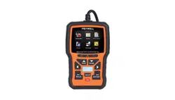
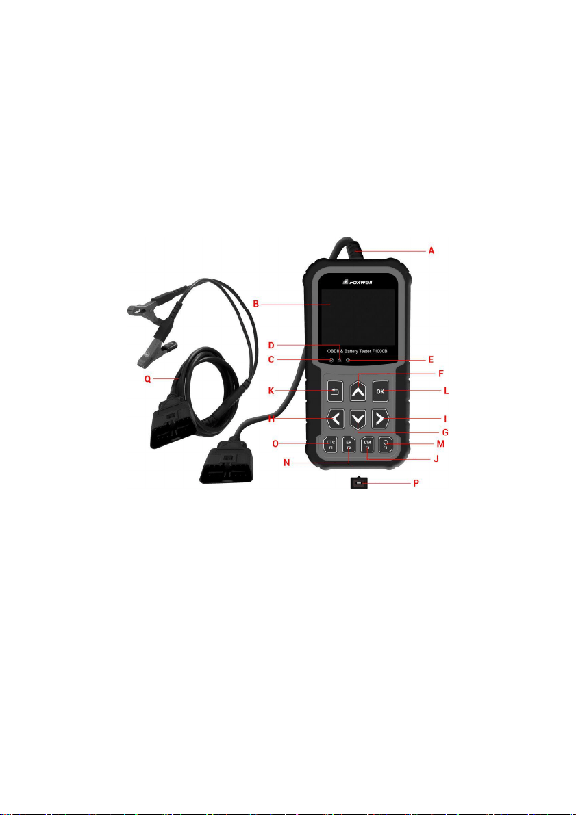
2.1 OBDII &Battery Tester Descriptions
This section illustrates external features, ports and connectors of the OBDII&Battery tester.
Figure 2-1 Front View
A. OBD II Cable- provides communication for vehicle DLC.
B. LCD Display - shows menus, test results and operation tips.
C. Green LED Display- indicates the engine system is working normally (all monitors on the
vehicles are active and performing their diagnostic testing), and no DTCs are found.
D. Yellow LED Display- shows the tool finds a possible problem. Pending DTCs exist or/and
some of the vehicle’s emission monitors have not run their diagnostic testing.
E. Red LED Display -indicates there are some problems in one or more of the vehicle’s systems.
In this case, the MIL lamp on the instrument panel is on.
F. UP Key - quick access to the Read Codes function before going to diagnostic menu and moves
selection up. When looking up DTC, it is used to change value of selected character.
G. DOWN Key - Quick access to the Clear Codes function before going to diagnostic menu and
moves selection down. When looking up DTC, it is used to change value of selected character.
H. LEFT SCROLL KEY-goes to previous character when looking up DTCs. Scrolls back and forth
through codes found and through different screens of data. Also it is used to make selection of
PIDs when viewing custom PID list, and to view PID graphs.
I. RIGHT SCROLL KEY-goes to next character when looking up DTCs. Scrolls back and forth
through codes found and through different screens of data. Also it is used to cancel all
selections of PIDs when viewing custom PID list.

Foxwell F1000B OBDII&Battery Tester User’s Guide_ English Version_V1.00
9
J. One Click I/M Readiness Key -quick checks state emissions readiness and drive cycle
verification.
K. BACK Key - cancels an action and returns to previous screen or level.
L. ENTER Key - confirms an action or movement and moves to next level.
M. HELP Key- accesses to the Help function and it is also used to update the OBDII&Battery
tester when long pressed.
N. ERASE Key - accesses to erase fault code.
O. DTC key- accesses to read diagnostic fault code.
P. USB Port – provides a USB connection between the OBDII&Battery tester and PC or laptop.
Q. BATTERY Clip –connect battery clips to device to perform battery testing function.
2.2 Accessory Descriptions
This section lists the accessories that go with the OBDII&Battery tester. If you find any of the
following items missing from your package, contact your local dealer for assistance.
1 User’s Manual - provides operation instructions for the usage of the OBDII&Battery tester.
2.Batter Clips- connect battery clips to device to perform battery testing function
3 USB Cable- provides connection between the OBDII&Battery tester and a computer to upgrade
the tool.
4 Quick Start Guide– includes the user’s manual, NT Wonder update software and update files.
2.3 Technical Specifications
Display: 2.8”TFT color display
Working Temperature: 0 to 60 ℃ (32 to 140℉)
Storage Temperature: -20 to 70℃ (-4 to 158℉)
Power Supply: 8-18V vehicle power
Supported Protocols:J1850PWM, J1850-VPW, ISO9141, KWP2000 (ISO 14230), and CAN
(Control Area Network ISO 11898)
Dimensions (L*W*H): 172*97.5*32mm
Weight: 0.6kg
3 Getting Started
This section describes how to provide power to the OBDII&Battery tester, provides brief
introductions of applications loaded on the OBDII&Battery tester and display screen layout and
illustrates how to input text and numbers with the OBDII&Battery tester.
3.1 Providing Power to OBDII&Battery Tester
Before using the OBDII&Battery tester, make sure to provide power to the OBDII&Battery tester.
The unit operates on any of the following sources:
●
12-volt vehicle power
●
USB connection to personal computer.
3.1.1 Connecting to Vehicle Power
The OBDII&Battery tester normally powers on whenever it is connected to the data link connector
(DLC).
To connect to vehicle power:
1. Locate the data link connector (DLC). The DLC is generally located under the dash on the
driver side of the vehicle.
Foxwell F1000B OBDII&Battery Tester User’s Guide_ English Version_V1.00
10
2. Connect the OBDII&Battery tester with the DLC.
3. Switch the ignition key to the ON position.
4. The OBDII&Battery tester automatically boots up.
IMPORTANT
Never try to provide power for the OBDII&Battery tester from USB connection when the
OBDII&Battery tester is communicating with a vehicle.
3.1.2 Connecting to Personal Computer with USB Cable
The OBDII&Battery tester also receives power through the USB port when it is connected to a PC
for updating software and transferring saved files.
To connect to PC:
1. Insert the small end of the USB cable to the USB port at the right side of the OBDII&Battery
tester and the large end to a computer.
2. Press the power switch of the OBDII&Battery tester to power it on.
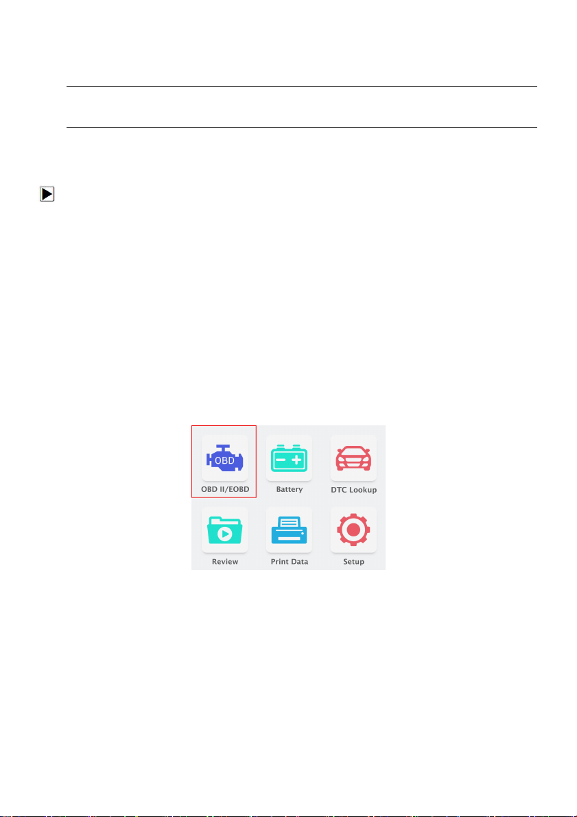
3.2 Application Overview
When the OBDII&Battery tester boots up, the Home screen opens. This screen shows all
applications loaded on the unit.
Following applications are preloaded into the OBDII&Battery tester:
● OBDII/EOBD – leads to OBDII screens for all 9 generic OBD system tests.
● Battery – leads to battery testing functions
● DTC Lookup – leads to screens for diagnostic trouble code lookup.
● Review – leads to screens for access to tested data files.
● Print Data – leads to screens for access to printing function
● Setup – leads to screens for adjusting default settings to meet your own preference when
using the OBDII&Battery tester.
Figure 3.1 Sample Home Screen
4 OBDII/EOBD Operations
OBD-II/EOBD menu lets you access all OBD service modes. According to ISO 9141-2, ISO
14230-4, and SAE J1850 standards, the OBD application is divided into several sub programs,
called ‘Service $xx’. Below is a list of OBD diagnostic services:
●Service $01 - request current power train diagnostic data
●Service $02 - request power train freeze frame data
●Service $03 - request emission-related diagnostic trouble codes
●Service $04 - clear/reset emission-related diagnostic information
●Service $05 - request oxygen sensor monitoring test results
●Service $06 - request on-board monitoring test results for specific monitored systems
●Service $07 - request emission-related diagnostic trouble codes detected during current or
last completed driving cycle
Foxwell F1000B OBDII&Battery Tester User’s Guide_ English Version_V1.00
11
●Service $08 - request control of on-board system, test or component
●Service $09 - request Vehicle Information
●Service $0A - request Emission related DTCs with permanent status
When Diagnostics application is selected from Home screen, the OBDII&Battery tester starts to
detect the communication protocol automatically. Once the connection has established, a menu
that lists all of the tests available on the identified vehicle displays. Menu options typically include:
● Read Codes
● Freeze Frame Data
● Erase Codes
● Live Data
● I/M Readiness
● O2 Sensor Test
● On-board Monitor Test
● Component Test
● Vehicle Information
● Modules Present
● Unit of measure
NOTE
Not all function options listed above are applicable to all vehicles. Available options may vary by
the year, model, and make of the test vehicle. A “The selected mode is not supported!” message
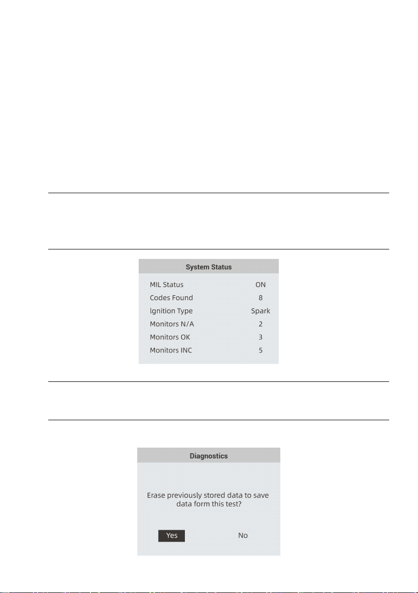
displays if the option is not applicable to the vehicle under test. When the OBDII&Battery tester
links to vehicle, it checks the status of I/M Monitors automatically, and gives a summary report on
the display as illustrated below.
Figure 4-1 Sample System Status Screen
NOTE
If vehicle is equipped with more than one computer module (for example a power train control
module [PCM] and a transmission control module [TCM]), the OBDII&Battery tester identifies
them by their identification names (ID) assigned by manufacturer (i.e. Engine or Module $A4).
A screen with prompted information to erase the previously stored data in order to save the data
from this test displays as below.
Foxwell F1000B OBDII&Battery Tester User’s Guide_ English Version_V1.00
12
Figure 4-2 Sample Erase the Previous Stored Data Screen
If previous data is to be erased, select Yes; if data is not to be erased, Use the LEFT/RIGHT key
to pick No. Wait a few seconds to return to Diagnostic Menu.
NOTE
If no data is stored in the OBDII&Battery tester, the above screen will not show up.
4.1 Read Codes
Read Codes menu lets you read stored codes, pending codes and permanent does found in the
control unit. Typical menu options include:
●Stored Codes
● Pending Codes
● Permanent Codes
Diagnostic trouble codes stored in a control module are used to help identify the cause of a
trouble or troubles with a vehicle. These codes have occurred a specific number of times and
indicate a problem that requires repair.
Pending codes are referred to as maturing codes that indicate intermittent faults. If the fault does
not occur within a certain number of drive cycles (depending on vehicle), the code clears from
memory. If a fault occurs a specific number of times, the code matures into a DTC and the MIL
illuminates or blinks.
Permanent Codes are DTCs that are "confirmed" and are retained in the non-volatile memory of
the computer until the appropriate monitor for each DTC has determined that the malfunction is
no longer present and is not commanding the MIL on. Permanent DTC shall be stored in
non-volatile memory and may not be erased by any diagnostic services or by disconnecting
power to ECU.
There are two ways to read codes using F1000B.
● Press the Read hot key to read codes from home screen.
● Traditional way: select Read Codes from the diagnostic menu.
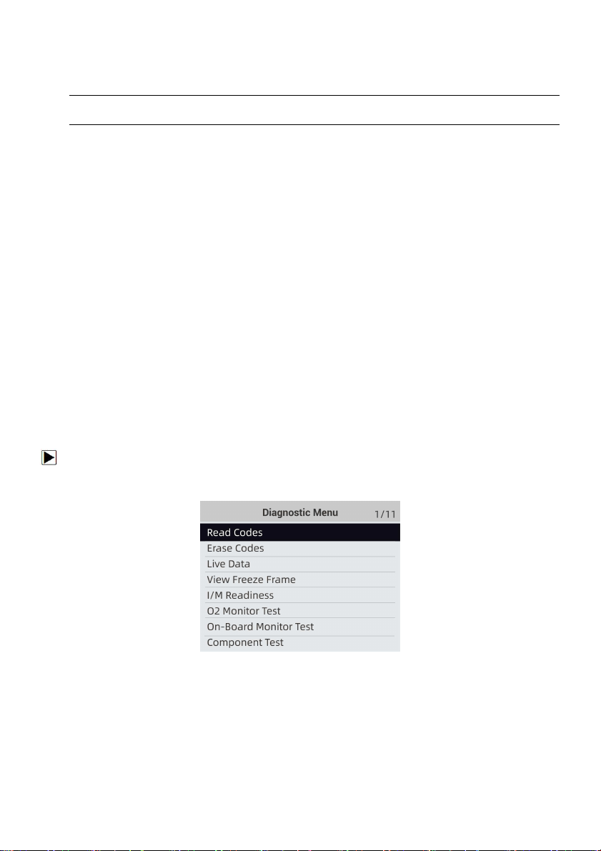
To read codes from a vehicle:
1. Press the Read hot key to directly read the codes from home screen. Or scroll with the
UP/DOWN key to highlight Read Codes from Diagnostic Menu and press the ENTER key.
Figure 4-3 Sample Diagnostic Menu Screen
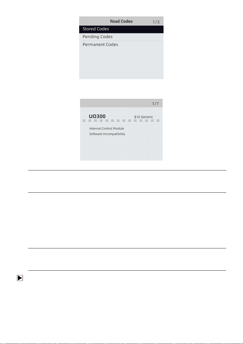
2. Select Stored Codes/Pending Codes/ Permanent Codes and press the ENTER key to
confirm.
Foxwell F1000B OBDII&Battery Tester User’s Guide_ English Version_V1.00
13
Figure 4-4 Sample Read Codes Screen
3. A code list including code number and its description displays.
Figure 4-5 Sample DTC Description Screen
NOTE
If no DTCs are present, the message “No (Pending) Codes Found!” is displayed. If any
manufacturer specific or enhanced codes detected, F1000B reads the correct DTC information
automatically according to the VIN.
4.2 Erase Codes
Erase Codes menu lets you to clear all current and stored DTCs from the control module. Also it
erases all temporary ECU information, including freeze frame. So make sure that the selected
system are completely checked and serviced by technicians and no vital information will be lost
before clearing codes.
There are two ways to erase codes:
● Press the Erase hot key to erase codes from home screen.
● Traditional way: select Erase Codes from the diagnostic menu.
NOTE
●
To clear codes, make sure that the ignition key is switched to ON with the engine off.
●
Erase Codes does not fix the problem that caused the fault! DTCs should only be erased after
correcting the condition(s) that caused them.
To clear codes:
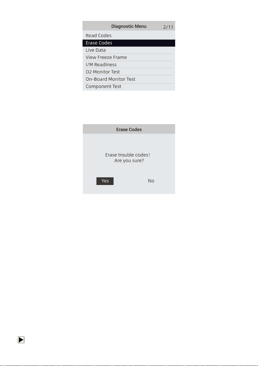
1. Press the Erase hot key to directly erase the codes from the home menu. Or use the
UP/DOWN key to highlight Erase Codes from Diagnostic Menu and press the ENTER key.
Foxwell F1000B OBDII&Battery Tester User’s Guide_ English Version_V1.00
14
Figure 4-6 Sample Diagnostic Menu Screen
2. Follow the on-screen instructions and answer questions about the vehicle being tested to
complete the procedure.
Figure 4-7 Sample Erase Codes Screen
3. Check the codes again. If any codes remain, repeat the Erase Codes steps.
4.3 Live Data
Live Data menu lets you view, record and playback real time PID data from the electronic control
module.
Menu options typically include:
● View Data
● Record Data
● Playback Data
4.3.1 View Data
The View Data function allows real time viewing of the vehicle’s electronic control unit’s PID data,
including sensor data, operation of switches, solenoids and relays.
Menu options typically include:
● Complete Data
● Custom Data
● Unit of measure (Please refer to Chapter 7System Setup)
4.3.1.1 Complete Data Set
Complete Data Set displays all supported PIDs of the vehicle being tested.
To view all live PID data:
Foxwell F1000B OBDII&Battery Tester User’s Guide_ English Version_V1.00
15
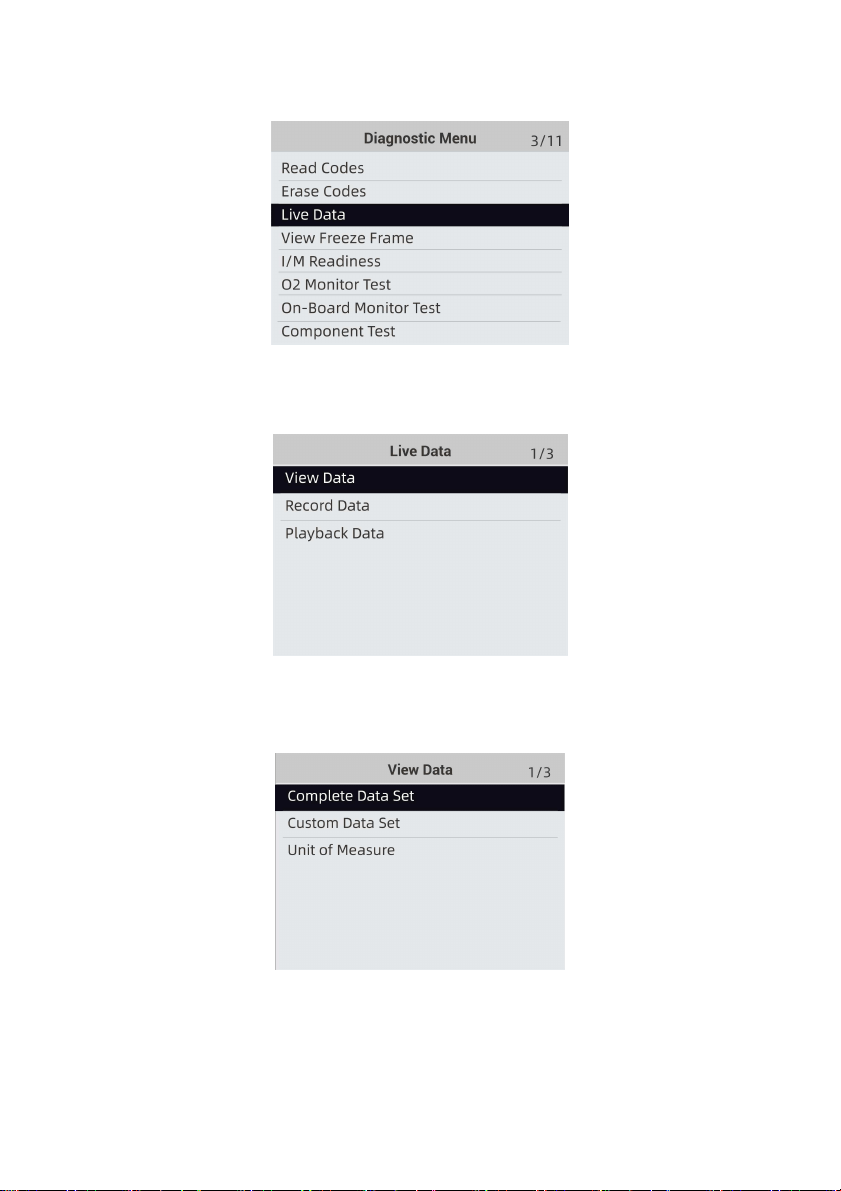
1. Use the UP/DOWN key to highlight Live Data from Diagnostic Menu and press the ENTER
key.
Figure 4-8 Sample Diagnostic Menu Screen
2. Select View Data from the list and press ENTER key to confirm.
Figure 4-9 Sample Live Data Menu Screen
3. Select Complete Data Set from the menu and press the ENTER key to display the data stream
screen.
Figure 4-10 Sample View Data Menu Screen
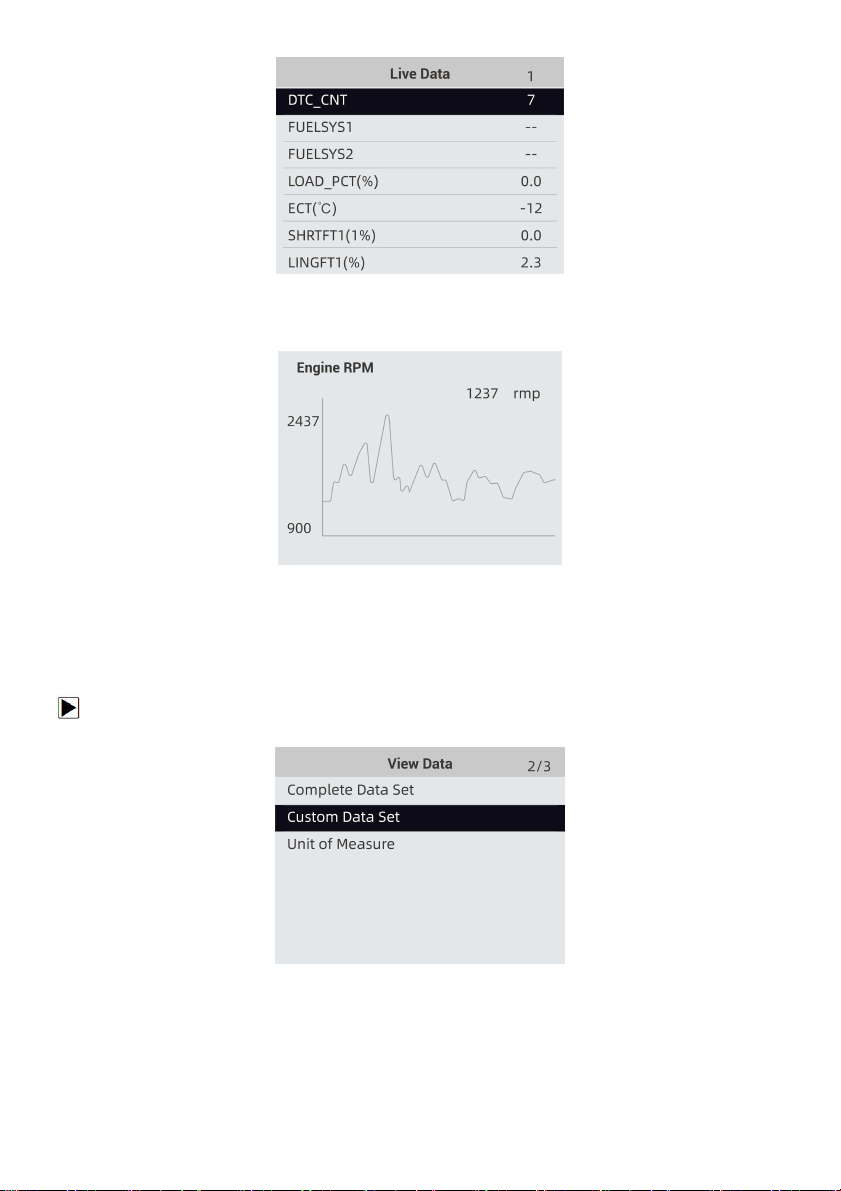
4. Scroll with the up and down arrow keys to scroll through data to select lines, and left and right
arrow keys to scroll back and forth through different screens of data.
Foxwell F1000B OBDII&Battery Tester User’s Guide_ English Version_V1.00
16
Figure 4-11 Sample Complete List Screen
5. Press the ENTER key to view PID graph if the PID gives a numeric reading.
Figure 4-12 Sample PID Graph Screen
6. Use the BACK key to return to diagnostic menu.
4.3.1.2 Custom Data List
Custom Data List menu lets you to minimize the number of PIDs on the data list and focus on any
suspicious or symptom-specific data parameters.
To create a custom data list:
1. Select Custom List from the menu and press the ENTER key.
Figure 4-13 Sample Live Data Menu Screen
2. The custom data stream selection screen displays.
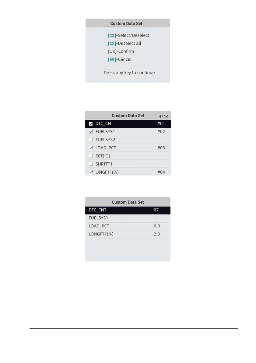
Foxwell F1000B OBDII&Battery Tester User’s Guide_ English Version_V1.00
17
Figure 4-14 Sample Custom Data stream Selection Screen
3. Use the RIGHT key to select or deselect a line or press LEFT key to deselect all if needed.
Press the ENTER key to confirm and BACK key to cancel.
Figure 4-15 Sample Custom Data stream Screen
4. When finished selection, press the ENTER key to display selected items.
Figure 4-16 Sample Data stream Screen
4.3.2 Record Data
The Record Data function is used to record PIDs to help diagnose intermittent drivability problems that
can’t be determined by any other method.
Menu options typically include:
●
Complete Data
●
Custom Data
●
Unit of measure (Please refer to Chapter 7 Set Up)
NOTE
There are two types of trigger methods used.
Foxwell F1000B OBDII&Battery Tester User’s Guide_ English Version_V1.00
18
●
Manual Trigger---triggers recording whenever operators press the ENTER key.
●
DTC trigger--- automatically triggers recording when a code is detected by vehicle. DTC Trigger
is not available on all vehicles. Some vehicles need to be driven for a long period of time to store
a code after a drivability fault occurs. If DTC trigger is selected to make a recording, there might
not be drastic change in the data before and after trigger.
Do not operate the OBDII&Battery tester while driving; always have two persons in vehicle when
recording – one to drive and the other to operate the OBDII&Battery tester.
To record data:
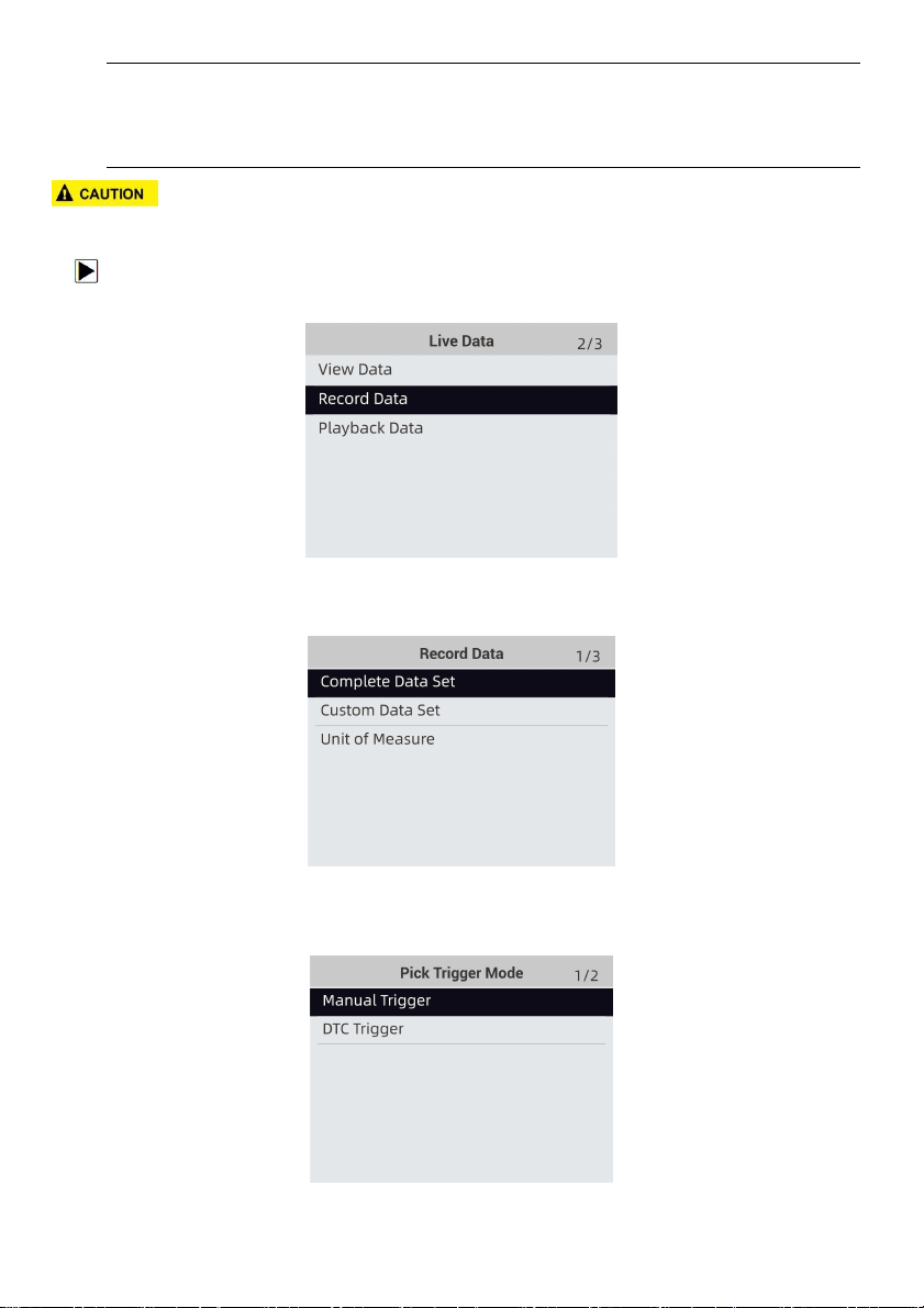
1. Select Record data from the menu and press the ENTER key.
Figure 4-17 Sample Live Data Menu Screen
2. Refer to View Data to set up Complete Data Set or Customer Data Set to record.
Figure 4-18 Sample Record Data Menu Screen
3. Scroll with the up and down arrow keys to pick a trigger mode and press the ENTER key to
confirm.
Figure 4-19 Sample Pick Trigger Mode Screen
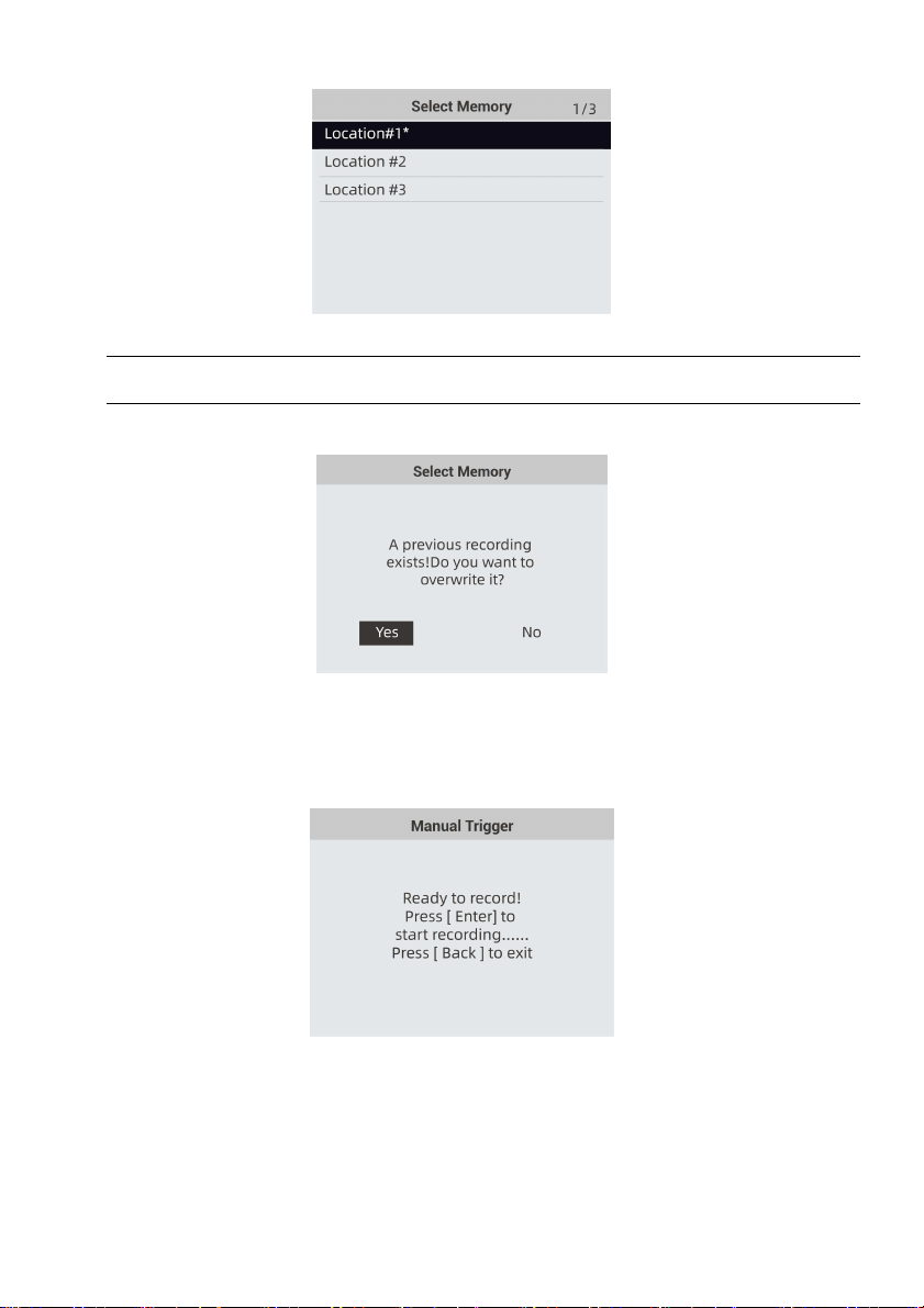
4. Use the UP/DOWN key to select a memory location and press ENTER to confirm.
Foxwell F1000B OBDII&Battery Tester User’s Guide_ English Version_V1.00
19
Figure 4-20 Sample Select Memory Screen
NOTE
The asterisk (*) on the screen indicates that a recording currently exists in this memory location.
If an area with an asterisk (*) was picked, a message prompting to erase data displays.
Figure 4-21 Sample Erase Recording Screen
5. If the recording is to be overwrited, selected Yes; if data is not to be overwrited, pick No to
return to Select Memory screen and choose another one.
6. If Manual Trigger is selected, following screen displays:
Figure 4-22 Sample Manual Trigger Recording Screen
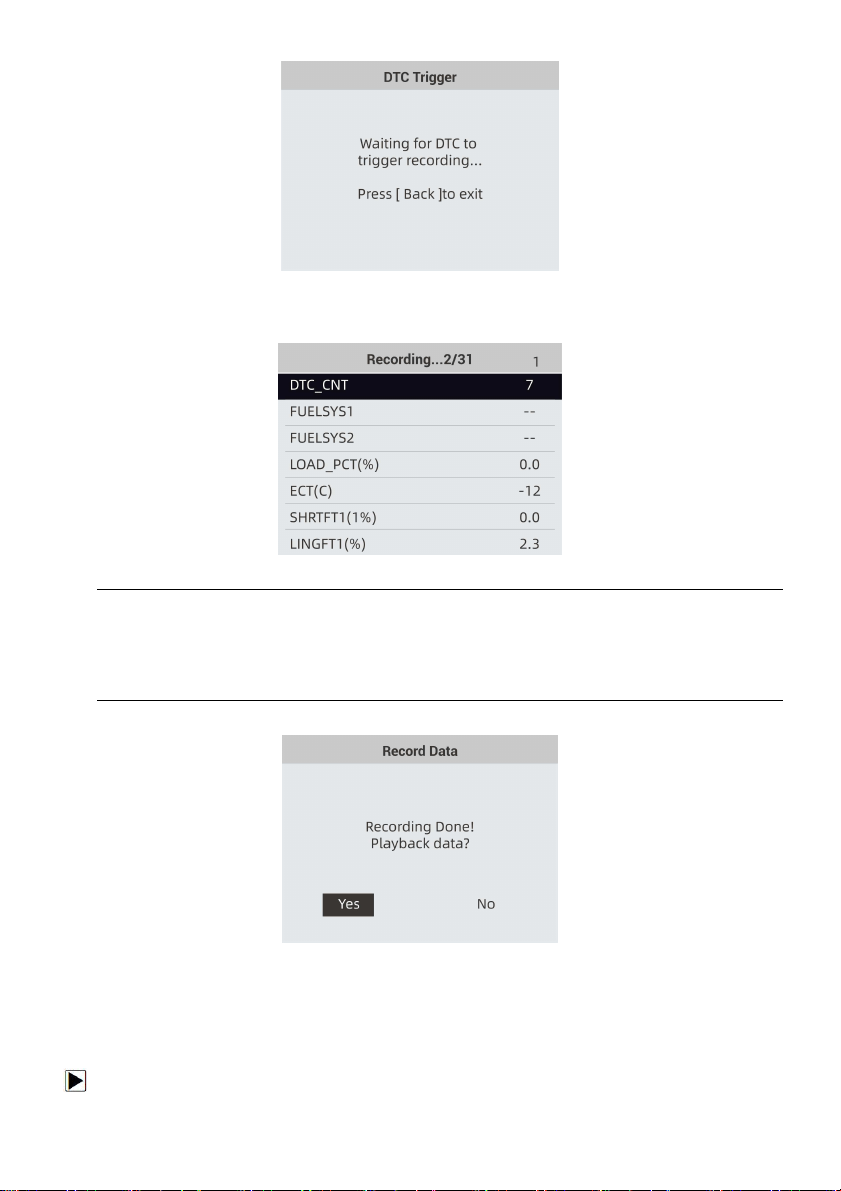
7. If DTC Trigger is picked, following screen displays:
Foxwell F1000B OBDII&Battery Tester User’s Guide_ English Version_V1.00
20
Figure 4-23 Sample DTC Trigger Recording Screen
8. Press the ENTER key to start recording or wait codes to trigger.
Figure 4-24 Sample Recording Screen
NOTE
Different vehicles communicate at different speeds and support a different number of PIDs.
Therefore, the maximum number of frames that can be recorded varies. The OBDII&Battery
tester keeps recording data until
●the memory is full.
● the operator presses the BACK key.
9. After recording, the OBDII&Battery tester displays a prompt to Playback.
Figure 4-25 Sample Record Data Screen
10. Select YES to view recorded data; pick NO or press the BACK key to return to Record Data.
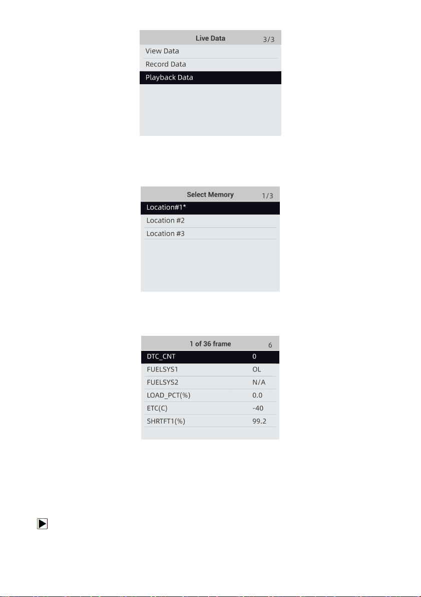
4.3.3 Playback Data
The Playback Data is used to playback recorded PID data.
To playback data:
1. Scroll with the up and down arrow key to select Play back Data from the Menu.
Foxwell F1000B OBDII&Battery Tester User’s Guide_ English Version_V1.00
21
Figure 4-26 Sample Record Data Screen
2. Use the UP/DOWN key to select a memory area that is marked with an asterisk (*) and press
the ENTER to confirm.
Figure 4-27 Sample Record Data Screen
3. Press the UP/DOWN key to view recorded PIDs of each frame. Press the BACK key to exit.
Figure 4-27 Sample Record Data Screen
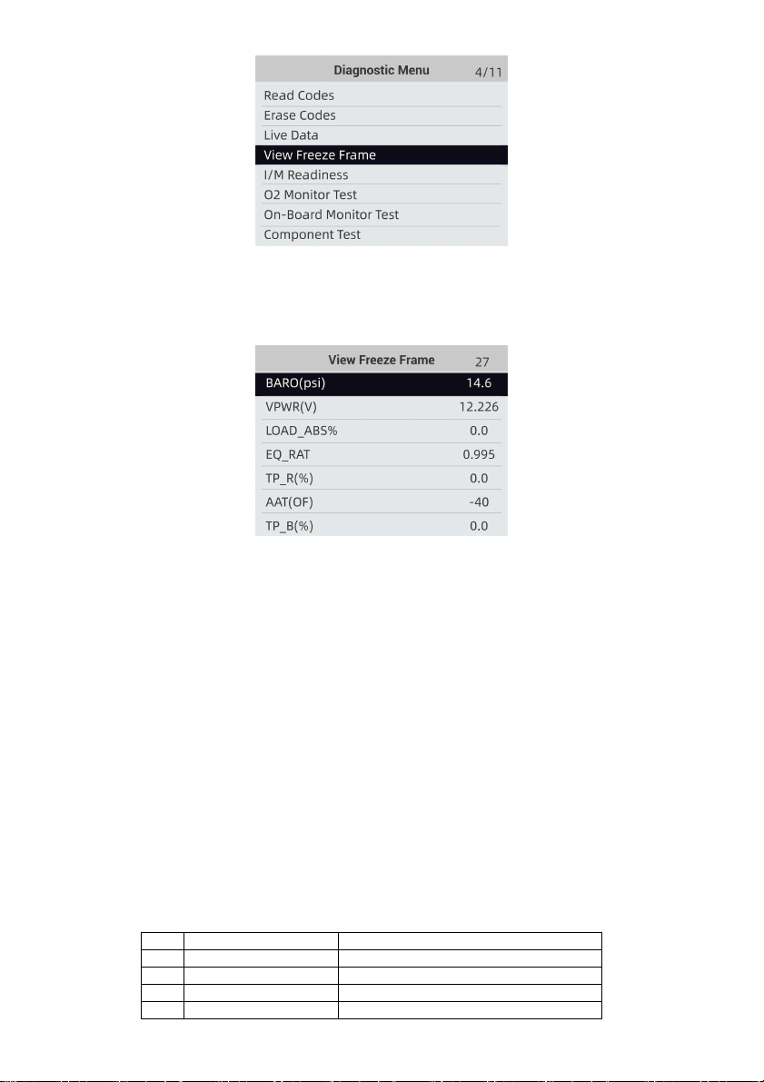
4.4 View Freeze Frame
Freeze Frame menu displays freeze frame data, a snapshot of critical vehicle operating
conditions automatically recorded by the on-board computer at the time of the DTC set. It is a
good function to help determine what caused the fault.
To view freeze frame data:
1. Select View Freeze Frame from the Diagnostic Menu. Details of freeze frame data displays.
Foxwell F1000B OBDII&Battery Tester User’s Guide_ English Version_V1.00
22
Figure 4-28 Sample Diagnostic Menu Screen
2. Use the up and down arrow keys to scroll through data to select lines, and left and right arrow
keys to scroll back and forth through different screens of data. If no freeze frame detected, the
message “No freeze frame data stored!” is displayed.
Figure 4-29 Sample Freeze Data Screen
3. Use the BACK key to return to Diagnostic Menu。
4.5 Read I/M Readiness Status Data
I/M Readiness option allows to view a snapshot of the operations for the emission system on
OBDII/EOBD vehicles.
I/M Readiness is a useful function used to check if all monitors are OK or N/A. The vehicle’s
computer performs tests on the emission system during normal driving conditions. After a specific
amount of drive time (each monitor has specific driving conditions and time required), the
computer’s monitors decide if the vehicles emission system is working correctly.
When the monitor’s status is:
●
OK - vehicle was driven enough to complete the monitor.
●
INC (Incomplete) - vehicle was not driven enough to complete the monitor.
●
N/A (Not Applicable) - vehicle does not support that monitor.
There are two types of I/M Readiness tests:
●
Since DTCs Cleared - shows status of the monitors since the DTCs were last cleared.
●
This Drive Cycle - shows status of monitors since the start of the current drive cycle.
Below is a list of abbreviations and names of OBD II monitors supported by the OBDII&Battery
tester.
No.
Abbreviation
Name
1
Misfire Monitor
Misfire Monitor
2
Fuel System Mon
Fuel System Monitor
3
Comp. Component
Comprehensive Components Monitor
4
Catalyst Mon
Catalyst Monitor
Foxwell F1000B OBDII&Battery Tester User’s Guide_ English Version_V1.00
23
5
Htd Catalyst
Heated Catalyst Monitor
6
Evap System Mon
Evaporative System Monitor
7
Sec Air System
Secondary Air System Monitor
8
A/C Refrig Mon
Air Conditioning Refrigerant Monitor
9
Oxygen Sens Mon
Oxygen Sensor Monitor
10
Oxygen Sens Htr
Oxygen Sensor Heater Monitor
11
EGR System Mon
Exhaust Gas Recirculation System
Monitor
There are two ways to retrieve I/M Readiness Status data:
● One-click I/M readiness key
● Typical way: select I/M Readiness from Diagnostic Menu
NOTE
●
To review I/M Readiness status, make sure that the ignition key is switched to ON with the
engine off.
●
Not all monitors are supported by all vehicles.
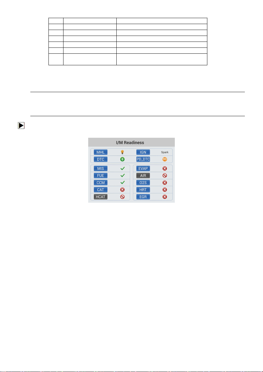
To retrieve I/M Readiness Status data by one-click I/M readiness key:
1. Press the One-Click I/M Readiness Key on the keypad and the following screen displays.
Figure 4-30 Sample Diagnostic Menu Screen
2. Colored LED and build-in beeper provide both visual and audible reminders for emission
check and DTCs. Below is the interpretation of the LED and build-in beeper.
When the LED is :
● Green - Indicates that engine systems are “OK” and working properly (the number of
Monitors equipped with the vehicle which have run and performed their self-diagnostic
testing is in the allowed range. MIL is off. ).No stored and pending DTCs exist. The
vehicle is ready for an Emissions Test.
● Yellow - The tool finds a possible problem. It indicates the following two conditions:
(1) Pending DTCs exist. Please check the I/M Readiness test result screen and use the
Read Codes function to view detailed codes information.
(2) Some of the vehicle’s emission monitors have not working properly. If the I/M
Readiness screen shows no DTC (including pending DTC), but the Yellow LED is
still illuminated, it indicate a “Monitor Has Not Run” status.
●Red- Indicates some problems exist with one or more of the vehicle’s system, and the
vehicle is not ready for an Emissions Test. As well there are DTCs found. The MIL lamp
on the vehicle’s instrument panel will light steady. The problem that is causing the
illumination of Red LED should be fixed before an Emissions Test or driving the vehicle
further.
The built-in beeper works with the colored LED simultaneous, as an assistance to reflect the I/M
Readiness test results:
●Green - two long beeps.
●Yellow - short, long, short beeps.
●Red - four short beeps.
Foxwell F1000B OBDII&Battery Tester User’s Guide_ English Version_V1.00
24
NOTE
The built-in beeper which makes different tones corresponding to different LED indicators is
invaluable when the test is performed while driving or in bright areas where LED illumination
may not be visible.
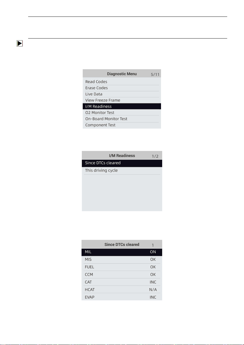
To retrieve I/M Readiness Status data by typical way:
1. Scroll with UP/DOWN key to highlight I/M Readiness from Diagnostic Menu and press the
ENTER key. If vehicle supports both types of monitors, a screen for monitor type selection
displays. Select a monitor type and press the ENTER key.
Figure 4-31 Sample Diagnostic Menu Screen
2. If the vehicle being tested supports both types of monitors, following screen displays.
Figure 4-29 Sample I/M Readiness Screen
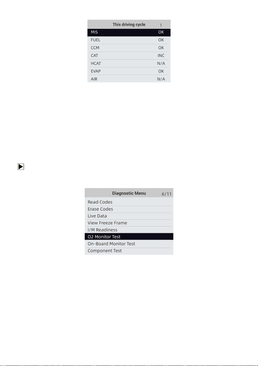
3. Depending on readiness test, one of these 2 screens will be present. Use the up and down
arrow keys to scroll through data. Press the BACK key to exit.
Figure 4-32 Sample IM Readiness Screen 1
Or
Foxwell F1000B OBDII&Battery Tester User’s Guide_ English Version_V1.00
25
Figure 4-33 Sample IM Readiness Screen 2
4.6 O2 Monitor Test
OBD II regulations require certain vehicles monitor and test oxygen (O2) sensors to isolate fuel
and emissions related faults. The O2 Monitor Test function is used to retrieve completed O2
sensors monitor test results.
The O2 Monitor Test is not an on-demand test. O2 sensors are not tested when selected via the
menu but tested when engine operating conditions are within specified limits.
If the vehicle uses a controller area network (CAN) protocol to communicate, this function is not
supported by vehicle. Refer to “On-Board Monitor Tests” on page 38-39 for O2 monitor data of
CAN-equipped vehicles.
To retrieve O2 monitor data:
1. Use the UP/DOWN key to highlight O2 Monitor Test from Diagnostic Menu and press the
ENTER key. A screen with a list of available sensors displays.
Figure 4-34 Sample Diagnostic Menu Screen
2. Use the UP/DOWN key to highlight an O2 sensor and press the ENTER key to confirm. A
screen with details of the selected sensor displays.
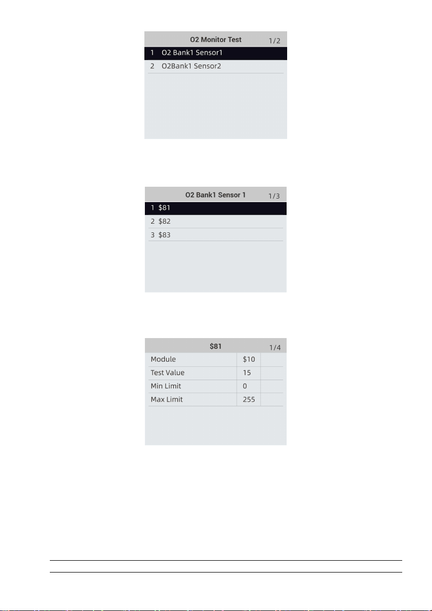
Foxwell F1000B OBDII&Battery Tester User’s Guide_ English Version_V1.00
26
Figure 4-35 Sample O2 Monitor Test screen
3. Use the up and down arrow keys to scroll through data to select lines, and left and right arrow
keys to scroll back and forth through different screens of data.
Figure 4-36 Sample O2 Bank1 Sensor 1 Screen
4. Press ENTER key to view data of selection.
Figure 4-37 Sample data of $81 screen
5. Press the BACK key to exit and return.
4.7 On-Board Monitor Test
The On-Board Monitor Test function is useful after servicing or after clearing a vehicle ECU’s
memory. It receives test results for emission-related power train components and systems that
are not continuously monitored for Non-CAN vehicles. And for CAN vehicles, it receives test data
for emission-related power train components and systems that are and are not continuously
monitored. It is vehicle manufacturer who is responsible for assigning test and component IDs.
NOTE
Foxwell F1000B OBDII&Battery Tester User’s Guide_ English Version_V1.00
27
Test results do not necessarily indicate a faulty component or system.
To request on-board monitor test results:
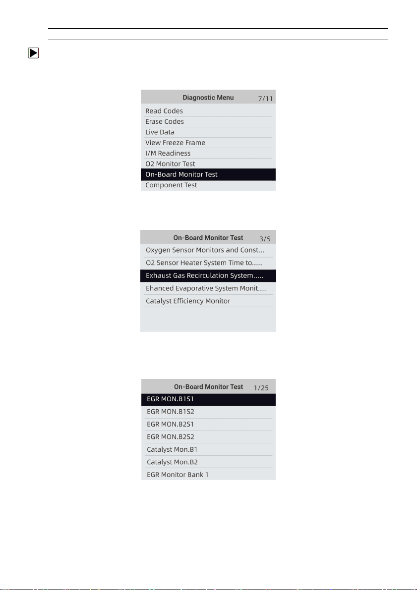
1. Use the UP/DOWN key to highlight On-Board Monitor Test from Diagnostic Menu and press
the ENTER key.
Figure 4-38 Sample Diagnostic Menu Screen
2. Depending on the protocol the vehicle used, one of these 2 screens shows.
Figure 4-39 Sample Non-CAN Vehicle Test Screen
Or
Figure 4-40 Sample CAN vehicle test screen
3. Use the UP/DOWN key to highlight a test group and press the ENTER key to confirm. A screen
with details of the selected sensor displays. Use the up and down arrow keys to scroll through
data to select lines, and left and right arrow keys to scroll back and forth through different
screens of data.
For non-CAN vehicles, test screen is illustrated as below:
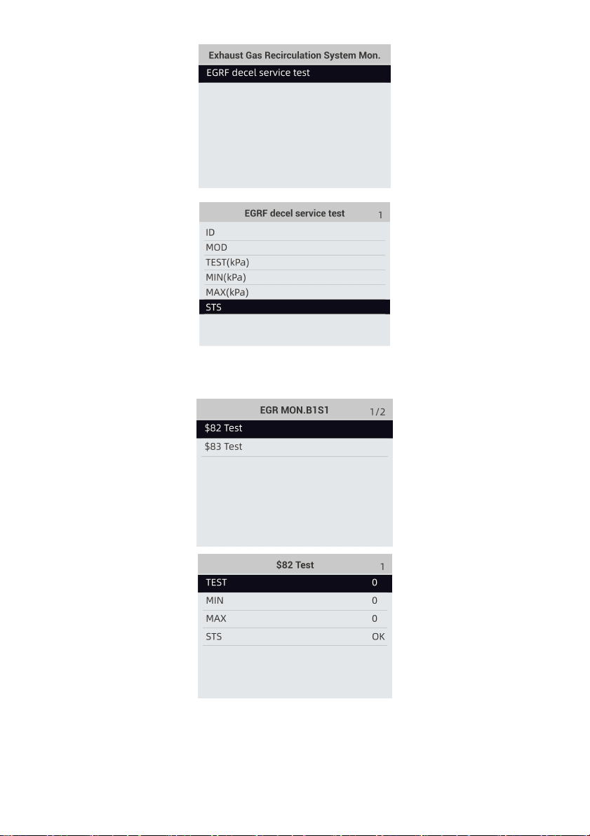
Foxwell F1000B OBDII&Battery Tester User’s Guide_ English Version_V1.00
28
Figure 4-41 Sample Non-CAN vehicle test screen
For CAN vehicles, test screen is illustrated as below:
Figure 4-42 Sample Can vehicle test screen
4. Press the BACK key to exit and return.
4.8 Component Test
Foxwell F1000B OBDII&Battery Tester User’s Guide_ English Version_V1.00
29
Component Test allows the OBDII&Battery tester to control operation of vehicle components,
tests or systems.
NOTE
●
Some manufacturers do not allow tools to control vehicle systems.
●
The manufacturer sets the criteria to automatically stop test. Refer to appropriate vehicle service
manual before using this function.
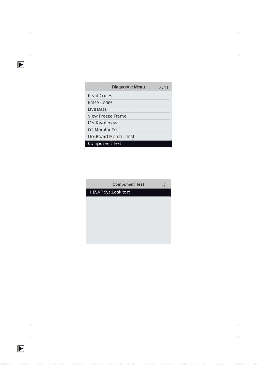
To perform a component test:
1. Use the UP/DOWN key to highlight Component Test from Diagnostic Menu and press the
ENTER key. A screen with a list of available tests displays.
Figure 4-43 Sample Diagnostic Menu Screen
2. Use the UP/DOWN key to highlight a system or component, press the ENTER key to start test
and the OBDII&Battery tester displays the message “Command Sent!”.
Figure 4-44 Sample Component test screen
3. Press the BACK key to exit and return.
4.9 Request Vehicle Information
Vehicle Information allows to request the vehicle’s VIN number, calibration ID(s) which identifies
software version in vehicle control module(s), calibration verification numbers (CVN(s)) and
in-use performance tracking on model year 2000 and newer OBD II compliant vehicles.
CVNs are calculated values required by OBD II regulations. They are reported to check if
emission-related calibrations have been changed. Multiple CVNs may be reported for a control
module. It may take several minutes to do the CVN calculation. In-use performance tracking
tracks performance of key readiness monitors.
NOTE
Available options will vary depending on the vehicle under test.
To request vehicle information:
Foxwell F1000B OBDII&Battery Tester User’s Guide_ English Version_V1.00
30
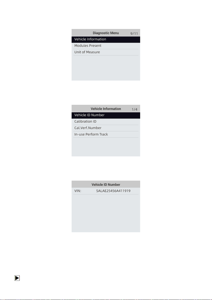
1. Use the UP/DOWN key to highlight Vehicle Info. from Diagnostic Menu and press the ENTER
key.
Figure 4-45 Sample Diagnostic Menu Screen
2. Follow on-screen instruction and send the command to read vehicle information. A screen with
a list of available options displays.
Figure 4-46 Sample Vehicle Info Screen
3. Use the UP/DOWN key to highlight an available option and press the ENTER key. A screen
with details of the selected option displays.
Figure 4-47 Sample Calibration ID Screen
4. Press the BACK key to exit and return.
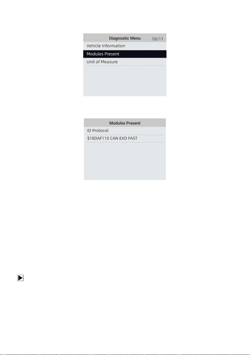
4.10 Modules Present
The OBDII&Battery tester identifies module IDs and communication protocols for OBD2 modules
in the vehicle.
To view module IDs and communication types:
Foxwell F1000B OBDII&Battery Tester User’s Guide_ English Version_V1.00
31
1. Use the UP/DOWN key to highlight Modules Present from Diagnostic Menu and press the
ENTER key.
Figure 4-48 Sample Diagnostic Menu Screen
2. A screen with the module IDs and protocols displays.
Figure 4-49 Sample Module Present Screen
3. Press the BACK key to exit and return.
5 Battery Testing Operations
This section describes how to use the OBDII&Battery tester to perform tests on car batteries and
charging systems. The menu-driven display will guide you step by step through the test process.
5.1 Connecting The OBDII&Battery Tester
The OBDII&Battery tester powers on automatically when it is correctly connected to the battery.
The preferred test position is at the battery terminals. If the battery is not accessible, you may test
at the jumper post; however, the power measurement may be lower than the actual value.
To connect the OBDII&Battery teste:
1. Clean the battery posts or side terminals.
2. Connect the red clamp to the positive (+) terminal and the black clamp to the negative (-)
terminal.
3. Rock the clamps back and forth to make sure the clamps are firmly connected.
Foxwell F1000B OBDII&Battery Tester User’s Guide_ English Version_V1.00
32
Figure 6-1 Sample Main Menu Screen
NOTE
Do not connect the OBDII&Battery tester to a voltage source greater than 30VDC; otherwise you
may damage the device.
NOTE
If you are testing inside a vehicle, make sure all accessory loads are cut off, the key is not in the
ON position and the doors are closed.
5.2 Battery Testing
F1000B 12 Volt Automotive Battery Analyzer allows you to analyze the battery healthy status and
view battery charging status.
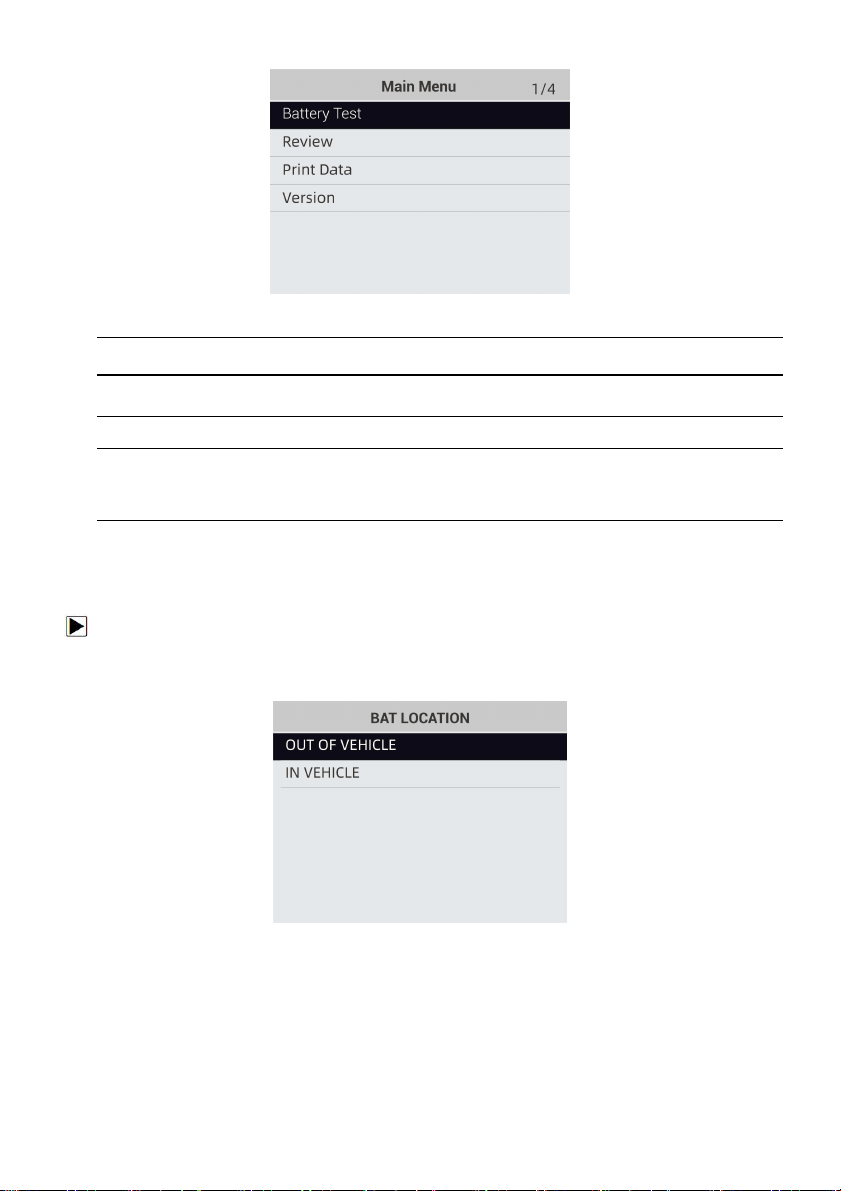
To start a battery test:
1. Press the ENTER button to start the test. BAT. LOCATION Menu will display.
Figure 6-2 Sample BAT.LOCATION Screen
2. Scroll with the UP or DOWN button to highlight OUT OF VEHICLE or IN VEHICLE from
BATTERY LOCATION menu and press ENTER to select the battery location.
Foxwell F1000B OBDII&Battery Tester User’s Guide_ English Version_V1.00
33
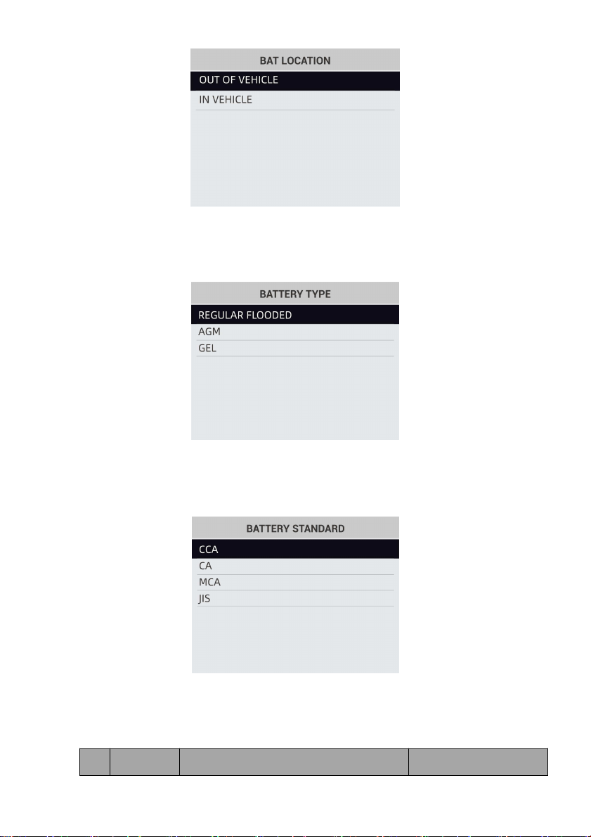
Figure 6-3 Sample BAT.LOCATION Screen
3. Scroll with the UP or DOWN button to select the battery type from BATTERY TYPE menu and
press ENTER to confirm.
Figure 6-4 Sample Battery Type Screen
4. Scroll with the UP or DOWN button to select the battery standard from BATTERY STANDARD
menu and press ENTER to confirm. Not all rating systems are available for each application.
Figure 6-5 Sample Battery Standard Screen
5. You may find the battery type and battery rating label on every battery.
Global Rating Systems:
No
Standard
Description
F1000B Testing Range
Foxwell F1000B OBDII&Battery Tester User’s Guide_ English Version_V1.00
34
1
CCA
Cold Cranking Amps, as specified by SAE.
The most common rating for cranking
batteries at 0°F (-18°C)
100-1100
2
CA
Cranking Amps standard. The effective
starting current value at 0°C (32°F).
100-1100
3
MCA
Marine Cranking Amps standard. The
effective starting current value at 0°C
(32°F).
100-1100
4
JIS
Japanese Industry Standard, shown on a
battery as a combination of numbers and
letters
26A17--245H52
5
DIN
Deutsche Industrie-Norm
100-1100
6
IEC
International Electro technical Commission
100-1100
7
EN
Europa-Norm
100-1100
8
SAE
Society of Automotive Engineers
100-1100
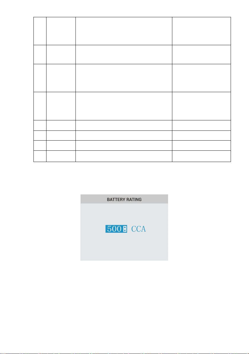
5. Use UP or DOWN button to change measure range till you enter the correct range of your
battery. Press ENTER to start the test.
Figure 6-6 Sample Battery Rating Screen
If the battery belongs to CCA standard, just select the corresponding CCA standard value and
press ENTER to start the testing.
6. View test results on the screen. Depending on battery status, one of the following test results
may display.

Foxwell F1000B OBDII&Battery Tester User’s Guide_ English Version_V1.00
35
Figure 6-7 Sample Battery Result Screen
No.
Test Results
Interpretation
1
GOOD BATTERY
The battery is in good condition.
2
GOOD-RECHARGE
The battery is in good condition but low current. Fully
charge the battery and return it to service.
3
CHARGE & RETEST
Fully charge the battery and retest. Failure to fully charge
the battery before testing may result in inaccurate results. If
you still get CHARGE & RETEST message after you fully
charge the battery, replace it.
4
REPLACE BATTERY
The battery is almost dead or the connection between the
battery and battery cable is poor. Replace the battery and
retest; or disconnect the battery cables and retest the
battery using the out-of-vehicle test before replacing it.
5
BAD CELL-REPLACE
The battery may be damaged such as broken cell or short
circuit. Replace the battery and retest.
7. Press the Back arrow button to exit the test.
NOTE:
The OBDII&Battery tester keeps the results of last test only. When you start a new test, the last
results are overwritten.
6. DTC Lookup
DTC Lookup menus allows to request DTC definitions stored in the OBDII&Battery tester.
To Look up DTCs:
Foxwell F1000B OBDII&Battery Tester User’s Guide_ English Version_V1.00
36
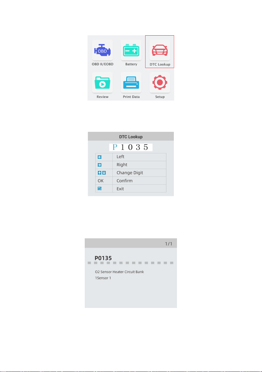
1. Use the LEFT/RIGHT key to highlight DTC Lookup from Home Screen and press the ENTER
key.
Figure 5-1 Sample Home Screen
2. Use the LEFT/RIGHT key to select the desired character, then press the UP/DOWN key to
change the digit you want to enter a valid code number. Press the ENTER key to confirm.
Figure 5-2 Sample DTC Lookup Screen
3. A screen with code number and its definition displays. If definition could not be found (SAE or
Manufacturer Specific), the OBDII&Battery tester displays “DTC definition not found! Please
refer to vehicle service manual!” If a P1xxx, C1xxx, B1xxx or U1xxx code is entered, select a
vehicle make to look for DTC definitions. Press the BACK key to exit.
Figure 5-3 Sample Trouble Codes Screen
Foxwell F1000B OBDII&Battery Tester User’s Guide_ English Version_V1.00
37
7 Review Data
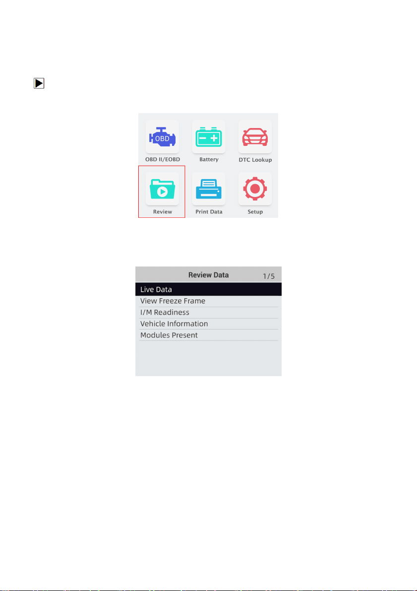
The Playback option leads to screens for review of recorded test results.
To review recorded data:
1. Use the LEFT/RIGHT key to highlight Review icon from home screen and press the ENTER
key.
Figure 7-1 Sample Home Screen
2. A screen with a list of test records displays. If no data is recorded, the message “No Data
available!” is displayed.
Figure 7-2 Sample Playback Screen
3. Use the UP/DOWN key to highlight an optional record and press the ENTER key. Details of the
test record displays. View and analysis the recorded information, then press BACK to exit.
8 Printing and Update
NT Wonder is an extremely easy-to-use that is used to update F1000B OBDII&Battery tester. Also, it
allows you to upload recorded test results to your PC or laptop for analysis and printing. Still, it enables
you to search DTC, read the manuals as well set up the language and style of the application.
This section illustrates how to use NT Wonder to perform its functions:
●
Updating the OBDII&Battery tester
●
Printing
●
Searching DTC
●
Read the manuals
●
Update tool settings
Foxwell F1000B OBDII&Battery Tester User’s Guide_ English Version_V1.00
38
8.1 Updating the OBDII&Battery Tester
F1000B is able to be updated to keep you stay current with the latest development of diagnosis. To
update the OBDII&Battery tester, you need following tools:
●F1000B OBDII&Battery tester
● Update Tool NTWonder
● PC or laptop with USB Ports and Internet explorer
● USB cable
To be able to use update tool, PC or laptop must meet the following minimum requirements:
● Operation System: Win98/NT, Win ME, Win2000, Win XP, VISTA and Windows 7.
● CPU: Intel PⅢ or better
● RAM: 64MB or better
● Hard Disk Space: 30MB or better
● Display: 800*600 pixel, 16 byte true color display or better
● Internet Explorer 4.0 or newer
IMPORTANT Do not disconnect the OBDII&Battery tester from computer, or power off the computer
during the process of updating.
To update the OBDII&Battery tester:
1. Download the update tool NT wonder and update files from our website and save the
applications and files in computer disk.
2. Unzip the update tool file. Follow instructions on computer screen to install the tool and driver.
3. Double click the desktop icon to launch the application.
4. Click Setting and select the language you want to update.
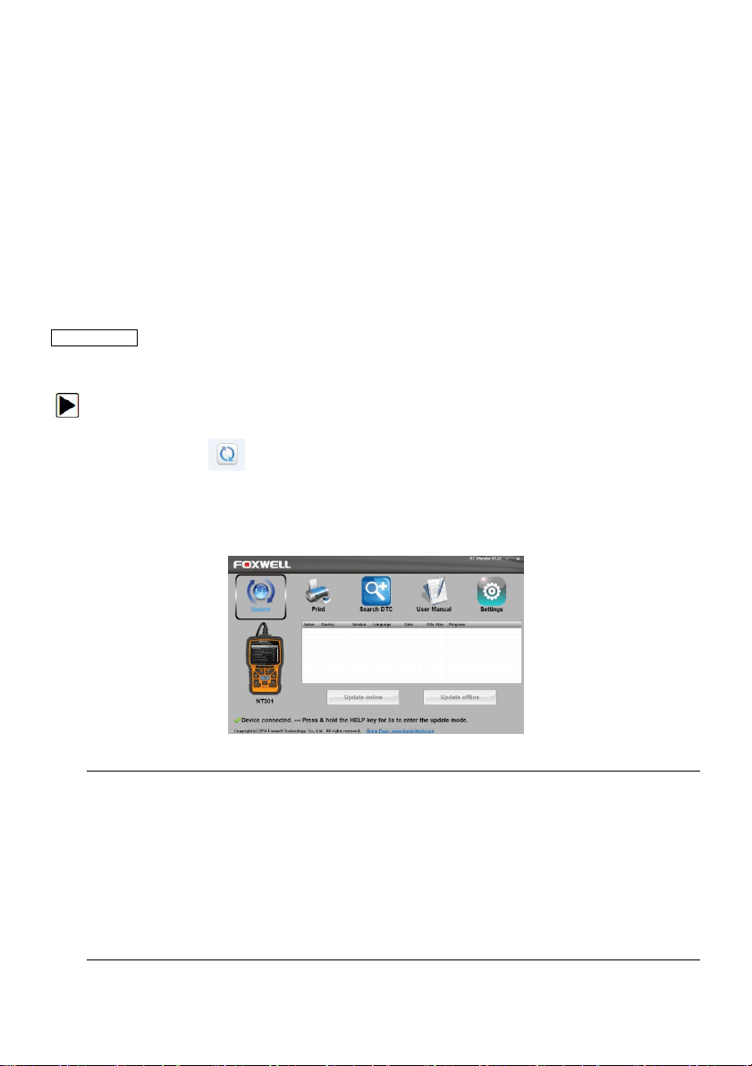
5. Connect F1000B to computer with the USB cable provided. Please press and hold the HELP
key while connecting the USD cable.
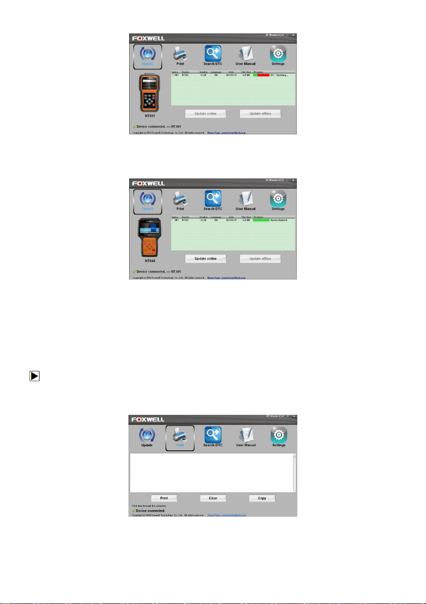
6. When F1000B enters the Update Mode, the application would detect it automatically.
Figure 9-1 Sample Update Mode Screen
NOTE
After entering update mode successfully, there are two different ways for you to update the
device.
●Update online: With internet connection, the tool NT Wonder automatically detects the software
version of the OBDII&Battery tester and read the latest software version from the server. If any
new diagnosis software found, it will automatically upgrade your F1000B.Otherwise a prompt of
new version not detected displays.
● Update offline:Update files will be automatically stored in your computer hard drive with every
successful online update. When picking Update offline, the update tool NT Wonder will detect
these local files automatically and display them in a list. Ticking one of them will lead to an update
process, which eliminates the need to download any file.
7. Click <Update online> or<Update offline>to start updating according to the software version
conditions.
Foxwell F1000B OBDII&Battery Tester User’s Guide_ English Version_V1.00
39
Figure 9-2 Sample Update Process Screen
8. A Update Finished Message displays when the update is completed.
Figure 9-3 Sample Update Done Screen
8.2 Printing
The Print Data function is used to print test results through computer. It is not available to perform this
function when the device is in Update Mode.
To print test results:
1. Download and launch NT Wonder as instructed on page 38 of 9.1 Updating the
OBDII&Battery tester.
2. Activate the application by clicking the Print Button from the menu.
Figure 9-4 Sample Printing Activation Function
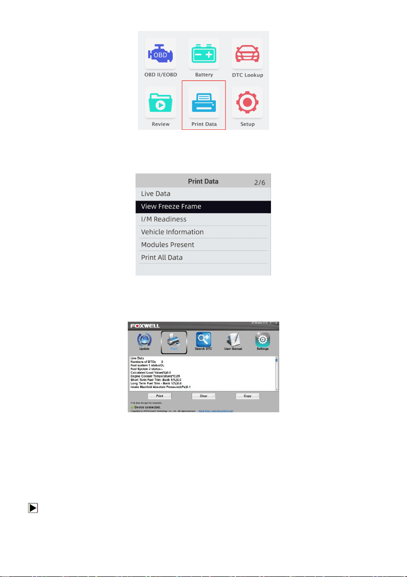
3. Connect F1000B to computer with the USB cable supplied to power it on.
4. Use the LEFT/RIGHT key to select Print Data from home screen of the F1000B and press the
ENTER key to confirm.
Foxwell F1000B OBDII&Battery Tester User’s Guide_ English Version_V1.00
40
Figure 9-5 Sample Home Screen Function
5. Use the UP/DOWN key to select desired data to print. If all recorded data to be printed, use the
UP/DOWN key to select Print All Data.
Figure 9-6 Sample Print Data Menu Screen
6. Press the ENTER key to load data to the edit box of update tool NT Wonder. Click the Clear
key to delete the data and Use Copy key to save the data to the clipboard on the computer. It
also allows the users to edit the text by moving the cursor to the edit box.
Figure 9-7 Sample Printing Data Screen.
7. With the printer correctly connected, use the Print key to print the testing data. Press the
BACK key to return to home screen.
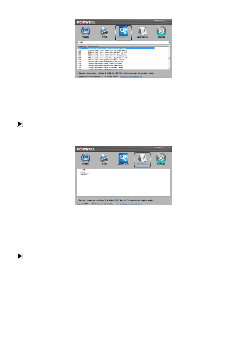
8.3 Searching DTC
Searching DTC option opens a screen that allows you to look up the DTC.
To search DTC:
1. Download and launch NT Wonder as instructed on page 44 of 9.1 Updating the
OBDII&Battery tester.
2. Start the printing application by clicking the Search DTC Button from the menu.
3. Input the valid code number and the definition of the code will be highlighted on the screen.
Foxwell F1000B OBDII&Battery Tester User’s Guide_ English Version_V1.00
41
Figure 9-8 Sample Search DTC Screen
8.4 User Manual
User Manual option opens a screen that allows you to read the manual in PDF format.
To read the manual:
1. Download and launch NT Wonder as instructed on page 38 of 9.1 Updating the OBDII&Battery
tester.
2. Activate the application by clicking the User Manual Button from the menu.
3. Double click to open the manual you want to check.
Figure 9-9 Sample User Manual Screen
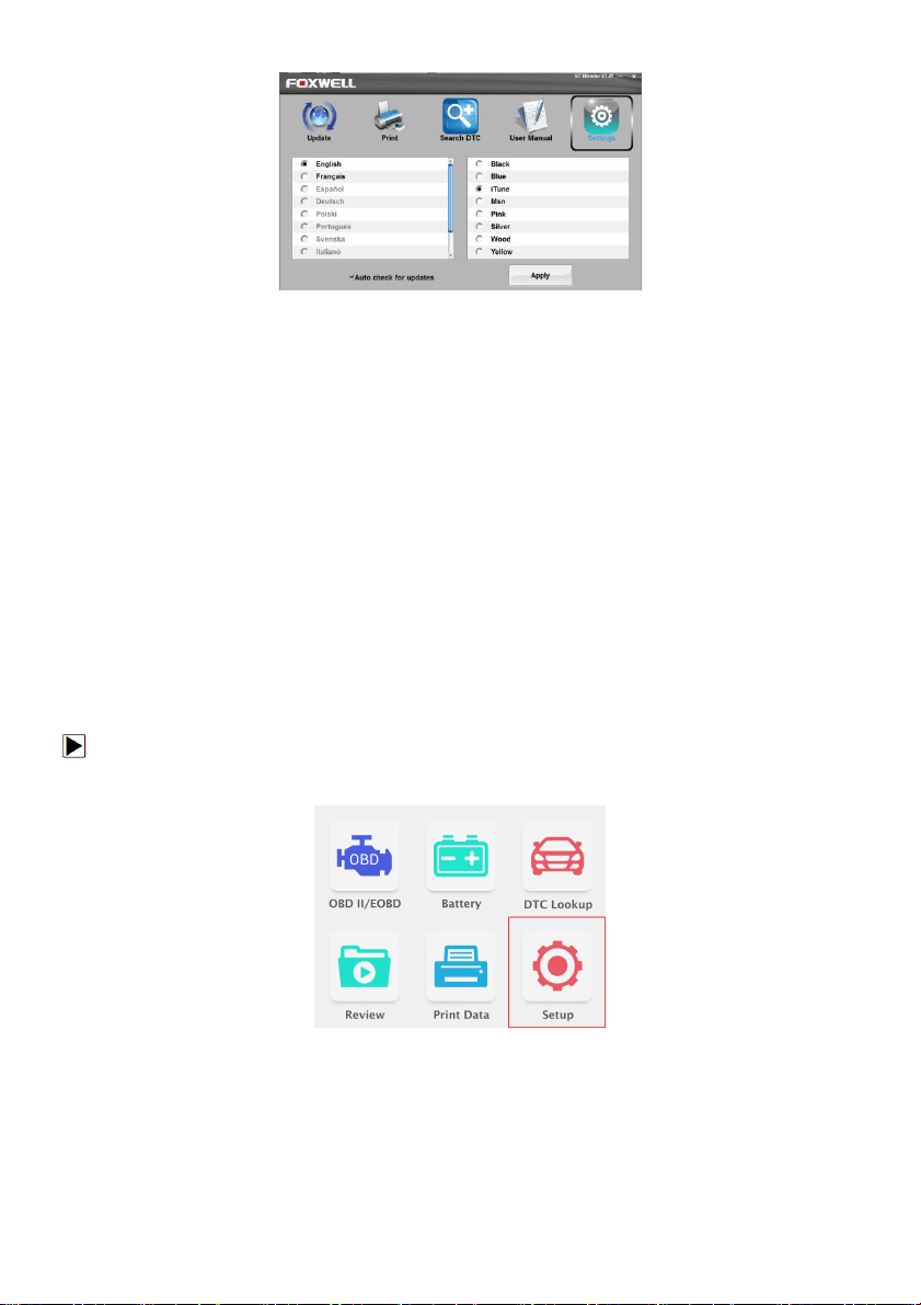
8.5 Update Tool Settings
Settings option opens a screen that allows you to set the language and style of the tool. Still, it offers
the option for you to automatically check the update files from the server.
To set up the update tool:
4. Download and launch NT Wonder as instructed on page 43 of 9.1 Updating the OBDII&Battery
tester.
1. Activate the application by clicking the Settings from the menu.
2. Select the language and the style you want from the left to right column.
3. Select and tick the “Auto check for updates” on the bottom of the screen, then press Apply key
to confirm.
Foxwell F1000B OBDII&Battery Tester User’s Guide_ English Version_V1.00
42
Figure 9-10 Sample Update Tool Setting Screen.
9 System Setup
This section illustrates how to program the OBDII&Battery tester to meet your specific needs.
When Setup application is selected, a menu with available service options displays. Menu options
typically include:
● Language
● Configure monitors
● Unit of measure
● Key Beep Set
● Diag Beep Set
● Tool self-test
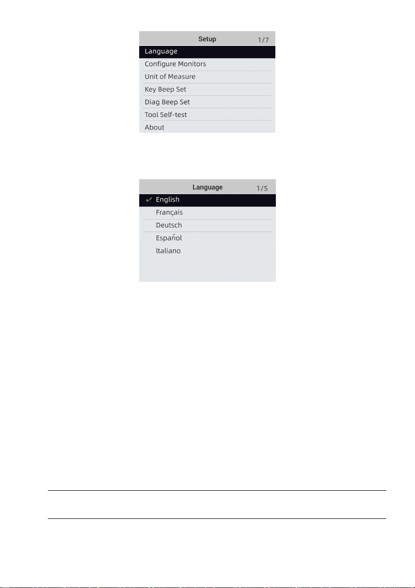
9.1 Select Language
Selecting Language opens a screen that allows you to choose system language.
To configure system language:
1. Use the LEFT/RIGHT key to highlight Setup from home screen and press the ENTER key.
Figure 8-1 Sample Home Screen
2. A screen of a list of menu options displays.
Foxwell F1000B OBDII&Battery Tester User’s Guide_ English Version_V1.00
43
Figure 8-2 Sample Setup Screen
3. Press the UP/DOWN key select a language and press the ENTER key to confirm. Press the
BACK key to exit and return.
Figure 8-3 Sample Language Selection Screen
9.2 Configure Monitors
This menu allows the users to configure the monitors required to test spark ignition and
compression ignition, the number of monitors to pass diagnosis, and restore the default settings.
Menu options typically include:
●
Spark IGN Required Monitors
● Compression IGN Required Monitors
●
Allowed INC Monitors
●
Reset Factory Default
There are two different types of monitors: continuous and non-continuous. Continuous monitors
are different in design from the non-continuous monitors. Continuous monitors are being
constantly tested and evaluated by the car’s computer while the car is running. Conversely, the
non-continuous monitors require certain conditions to be met before a test or series of tests can
be completed.
Continuous Monitors:
●
Misfire
●
Fuel System
●
Comprehensive Component
Non-Continuous Monitors:
NOTE
Non-continuous monitors are different for spark ignition cars (gasoline engines) and compression
ignition card (diesel engines).
Spark ignition vehicles (Gas)
●
Catalyst (CAT)
●
Heated Catalyst
Foxwell F1000B OBDII&Battery Tester User’s Guide_ English Version_V1.00
44
● Evaporative (EVAP) System
● Secondary Air System
● Oxygen (O2) Sensor
● Oxygen Sensor Heater
● EGR (Exhaust Gas Recirculation) and/or VVT System
Compression ignition vehicles (Diesel)
● NMHC Catalyst
● NOx/SCR After treatment
● Boost Pressure
● Exhaust Gas Sensor
● PM Filter
● EGR and/or VVT System
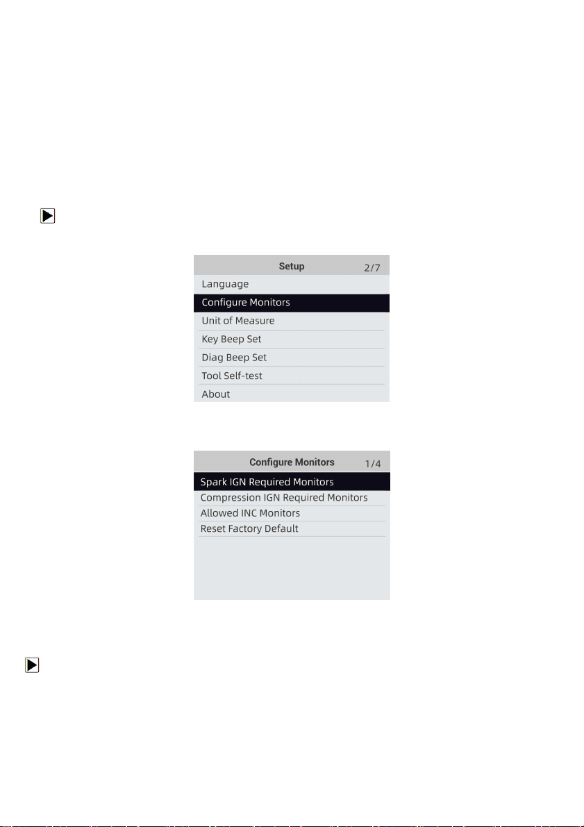
To configure monitors:
1. Use the UP/DOWN key to highlight Configure Monitors from Setup menu and press the
ENTER key to confirm.
Figure 8-4 Sample Setup Screen
2. A screen with the optional monitors to be configured displays.
Figure 8-5 Sample Configure Monitors Display
9.2.1 Spark IGN Required Monitors
In this menu, the operators can configure monitors for spark ignition cars (gasoline engines).
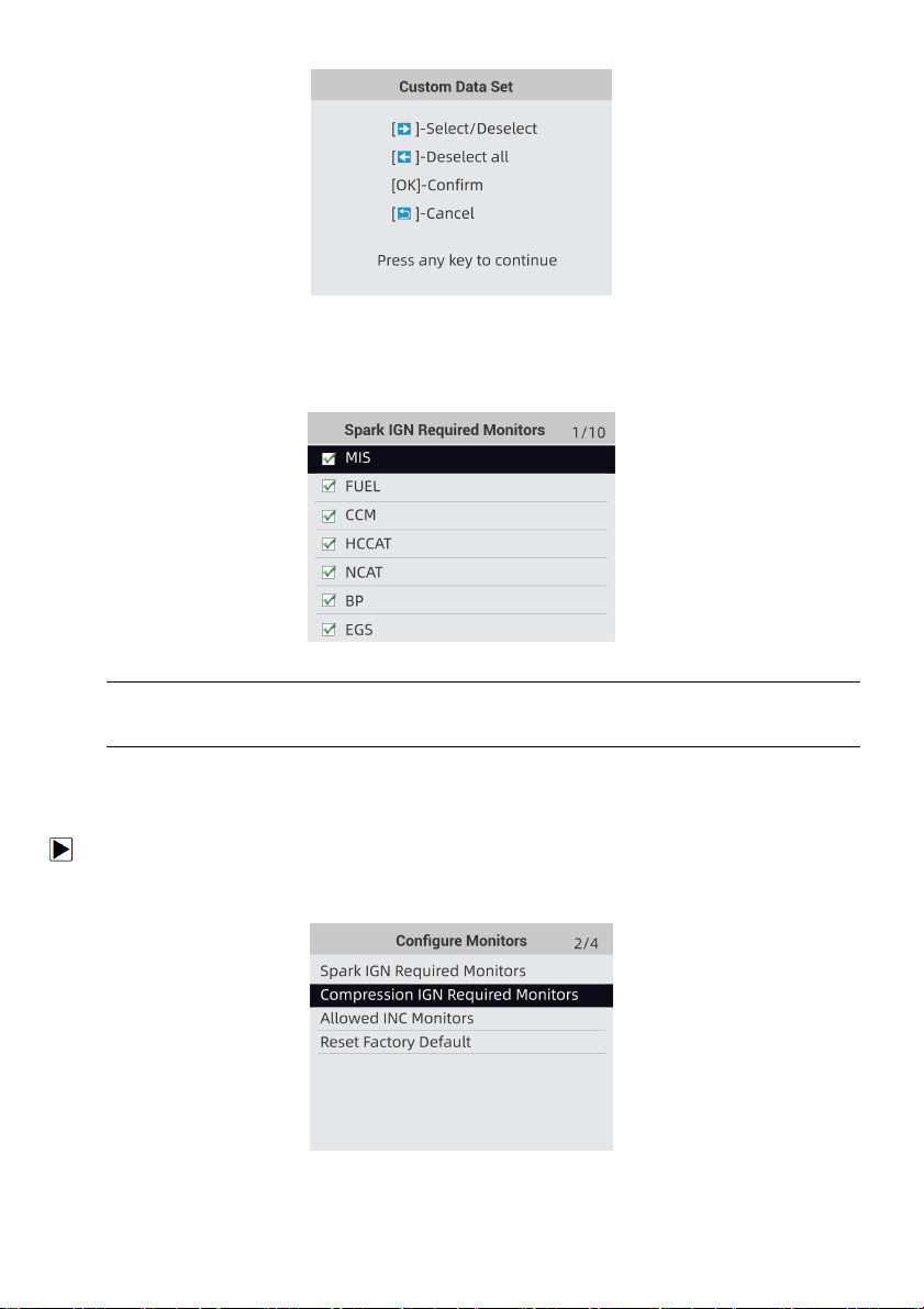
To configure spark IGN required monitors:
1. Use the UP/DOWN key to highlight Spark IGN Required Monitors from menu and press the
ENTER key to confirm.
2. The custom monitors selection screen displays.
Foxwell F1000B OBDII&Battery Tester User’s Guide_ English Version_V1.00
45
Figure 8-6 Sample Custom Monitors Selection Screen
3. Use the RIGHT key to select or deselect a monitor or press the LEFT key to deselect all the
monitors. Press the ENTER key to confirm and BACK key to cancel.
Figure8-7Sample Spark IGN Required Monitors Selection Screen
NOTE
The number to the upper right corner of display indicates the total number of optional monitors
and sequence of currently selected monitor.
9.2.2 Compression IGN Required Monitors
In this menu, the operators can configure monitors for compression ignition cars (diesel engines).
To configure spark compression required monitors:
1. Use the UP/DOWN key to highlight Compression IGN Required Monitors from the menu and
press the ENTER key to confirm.
Figure 8-8 Sample Configure Monitors Display
Foxwell F1000B OBDII&Battery Tester User’s Guide_ English Version_V1.00
46
2. The custom monitors selection screen displays and Use the RIGHT key to select or deselect a
monitor or press the LEFT key to deselect all the monitors. Press the ENTER key to confirm and BACK
key to cancel.
Figure8-9 Sample Spark IGN Required Monitors Selection Screen
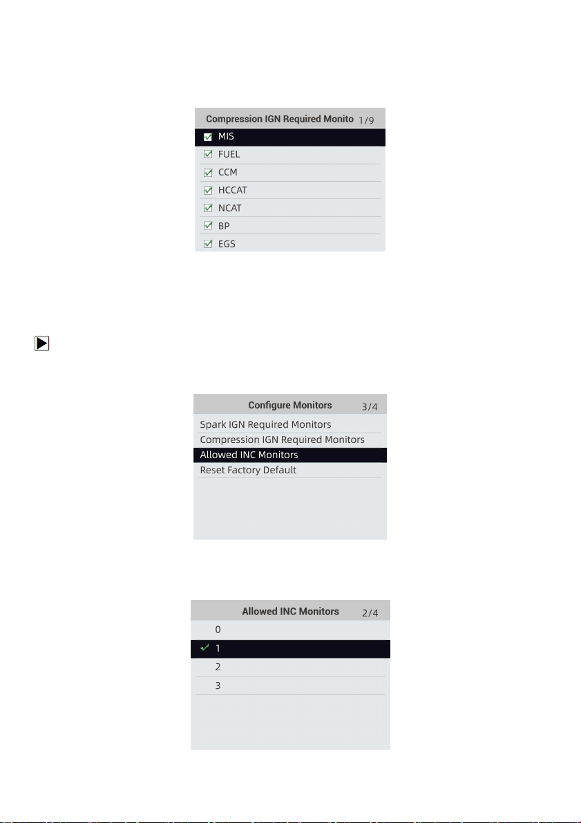
9.2.3 Allowed INC Monitors
Emissions tests vary depending on the geographic or regional area in which the vehicle is registered.
F1000B provides a more flexible way to meet different standards, which allows the user to select 0, 1, 2,
3 INC monitors in test.
To configure allowed INC monitors:
1. Use the UP/DOWN key to highlight Allowed INC Monitors from the menu and press the ENTER
key to confirm.
Figure8-9 Sample Configure Monitors Selection Screen
2. The custom INC monitors selection screen displays and scroll with the up and down arrow keys to
select. Press the ENTER key to confirm and BACK key to cancel.
Figure 8-10 Sample Allowed INC Monitors Selection Screen
Foxwell F1000B OBDII&Battery Tester User’s Guide_ English Version_V1.00
47
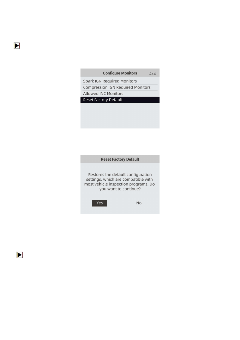
9.2.4 Reset Factory Default
This menu will allow the users to restore the default configuration settings in the Configure Monitors
menu, and delete any customized settings. In this case, it will include all the available monitors for the
Spark IGN Required Monitors and Compression IGN Required Monitors. Still the Allowed INC
Monitors will be set to 1.
To reset factory default:
1. Use the UP/DOWN key to highlight Reset Factory Default from the menu and press the ENTER
key to confirm.
Figure8-11 Sample Configure Monitors Selection Screen
2. A message prompting to reset factory default displays. Answer Yes to confirm the request or
answer No to abort and return.
Figure8-12 Sample Reset Factory Default Screen
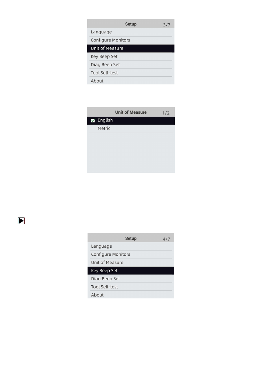
9.3 Unit of measure
Unit of measure opens a dialog box that allows you to choose between US customary or metric
units of measure.
To change the unit setup:
1. Scroll the UP/DOWN keys to highlight Unit of Measure from Setup menu and press the
ENTER key.
Foxwell F1000B OBDII&Battery Tester User’s Guide_ English Version_V1.00
48
Figure 8-13 Sample Setup Screen
2. Press the UP/DOWN arrow key select an item and press the ENTER key to save and return.
Figure 8-14 Sample Unit Selection Screen
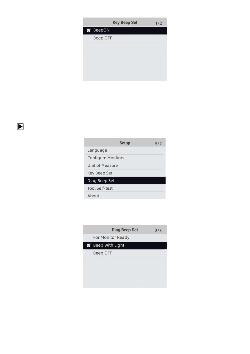
9.4 Key Beep Set
Key beep set opens a dialog box that allows you to turn on/off the built-in speaker for key
pressing.
To set the key beep:
1. Use the UP/DOWN key to highlight Key beep set from Setup menu and press the ENTER key.
Figure 8-15 Sample Setup Screen
2. Press the UP/DOWN arrow key select an item and press the ENTER key to save and return.
Foxwell F1000B OBDII&Battery Tester User’s Guide_ English Version_V1.00
49
Figure 8-16 Sample Beep Set Selection Screen
9.5 Diag Beep Set
Key beep set opens a dialog box that allows you to turn on/off the built-in speaker when
performing diagnostics.
To set the diag beep:
1. Use the UP/DOWN key to highlight Key Beep Set from Setup menu and press the ENTER key.
Figure 8-17 Sample Setup Screen
2. Press the UP/DOWN key to select an item and press the ENTER key to save and return.
Figure 8-18 Sample Diag Beep Selection Screen
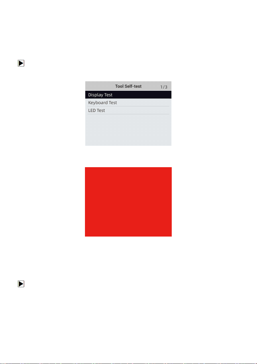
9.6 Tool Self-test
Key beep set opens a dialog box that allows you to check if the LCD display and the operation of
keypad and LED are working correctly. Typical menu includes:
● Display Test
Foxwell F1000B OBDII&Battery Tester User’s Guide_ English Version_V1.00
50
● Keypad Test
● LED Test
9.6.1 Display Test
Selecting Display Test option opens a screen that allows you to check the functionality of the
display.
To test the display:
1. Use the UP/DOWN key to highlight Display Test from Setup menu and press the ENTER key
to start test.
Figure 8-19 Sample Tool Self-test Screen
2. Check if there are any missing spots in the LCD screen.
Figure 8-20 Sample LCD Test Screen
3. To quit the test, press the BACK key.
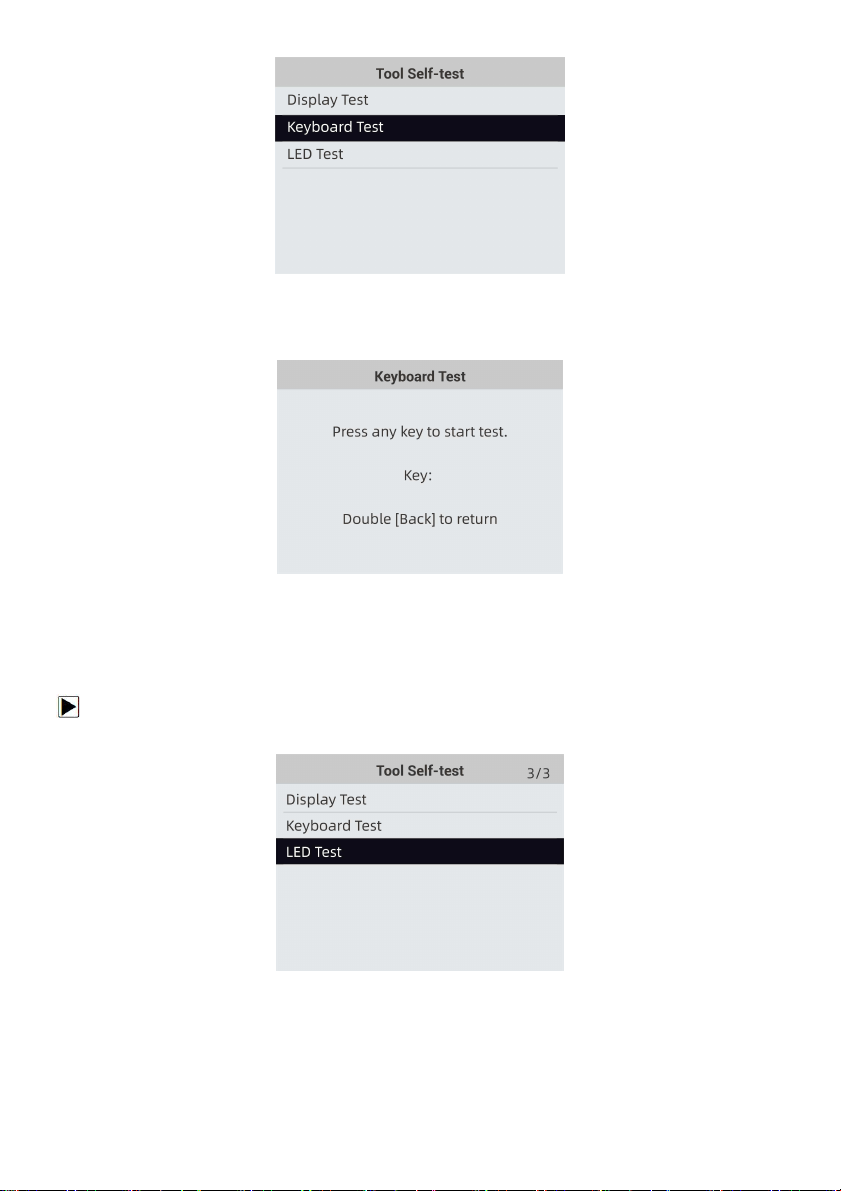
9.6.2 Keypad Test
Selecting Key Test option opens a screen that allows you to check the functionality of the keypad.
To test the keypad:
1. Use the UP/DOWN key to highlight Keyboard Test from Setup menu and press the ENTER
key.
Foxwell F1000B OBDII&Battery Tester User’s Guide_ English Version_V1.00
51
Figure8-21 Sample Tool Self- test Screen
2. Press any key to start test. Key name or scroll direction should show on display when you press
a key. Double press BACK to return.
Figure 8-22 Sample Key Test Screen
9.6.3 LED Test
Selecting LED Test option opens a screen that allows you to check the functionality of the LED.
To test the LED:
1. Use the UP/DOWN key to highlight LCD Test from Setup menu and press the ENTER key to
start test.
Figure 8-23 Sample Tool Self-test Screen
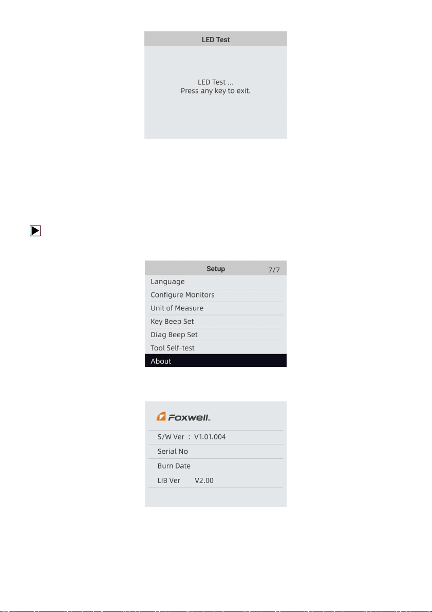
2. The Green Yellow Red indicators will flashing randomly, the indicators shall turn off when exit
by pressing any key.
Foxwell F1000B OBDII&Battery Tester User’s Guide_ English Version_V1.00
52
Figure 8-24 Sample LED Test Screen
4. To quit the test, press the any key.
9.7 Tool Information
Selecting About option opens a screen that show information about your OBDII&Battery tester,
such as serial number and software version.
To view information of your OBDII&Battery tester:
1. Use the LEFT/RIGHT key to highlight Setup from home menu and Highlight About press Enter
key.
Figure 8-25 Sample Home Screen
2. A screen with detailed information of the OBDII&Battery tester displays.
Figure 8-26 Sample Tool Information Screen
3. Press the BACK key to exit and return to the Setup menu.
< END >