Loading ...
Loading ...
Loading ...
12
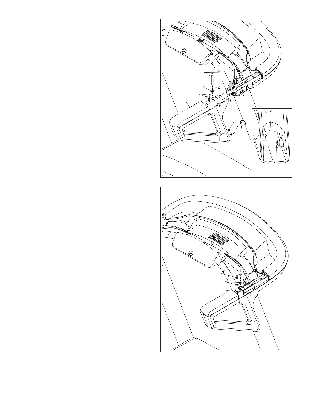
8. Identify the right handrail assembly (H). Remove
and discard the two indicated screws (I).
Next, carefully raise the Pulse Crossbar (93)
enough to allow you to slide the Handrail (86)
onto the console base assembly (G). See the
inset drawing. The Cover Bracket (18) should
slide into the indicated space (J) in the hand-
rail assembly.
Attach the right handrail assembly (H) with two
5/16" x 2 1/2" Screws (28) and two 5/16" Star
Washers (11); do not fully tighten the Screws
yet. Tip: You may need to adjust the position
of the right handrail assembly to align the
Screws properly.
Attach the left handrail assembly (not shown)
to the left side as described above.
9. IMPORTANT: To avoid damaging the Pulse
Crossbar (93), do not use power tools and do
not overtighten the #10 x 3/4" Screws (9).
Attach the Pulse Crossbar (93) to the right hand-
rail assembly (H) and the left handrail assembly
with four #10 x 3/4" Screws (9) and four #10 Star
Washers (5) (only one side is shown); start all
of the Screws, and then tighten them.
28
11
I
86
8
9
H
93
H
J
18
J
G
9
5
93
Loading ...
Loading ...
Loading ...