Loading ...
Loading ...
Loading ...
11
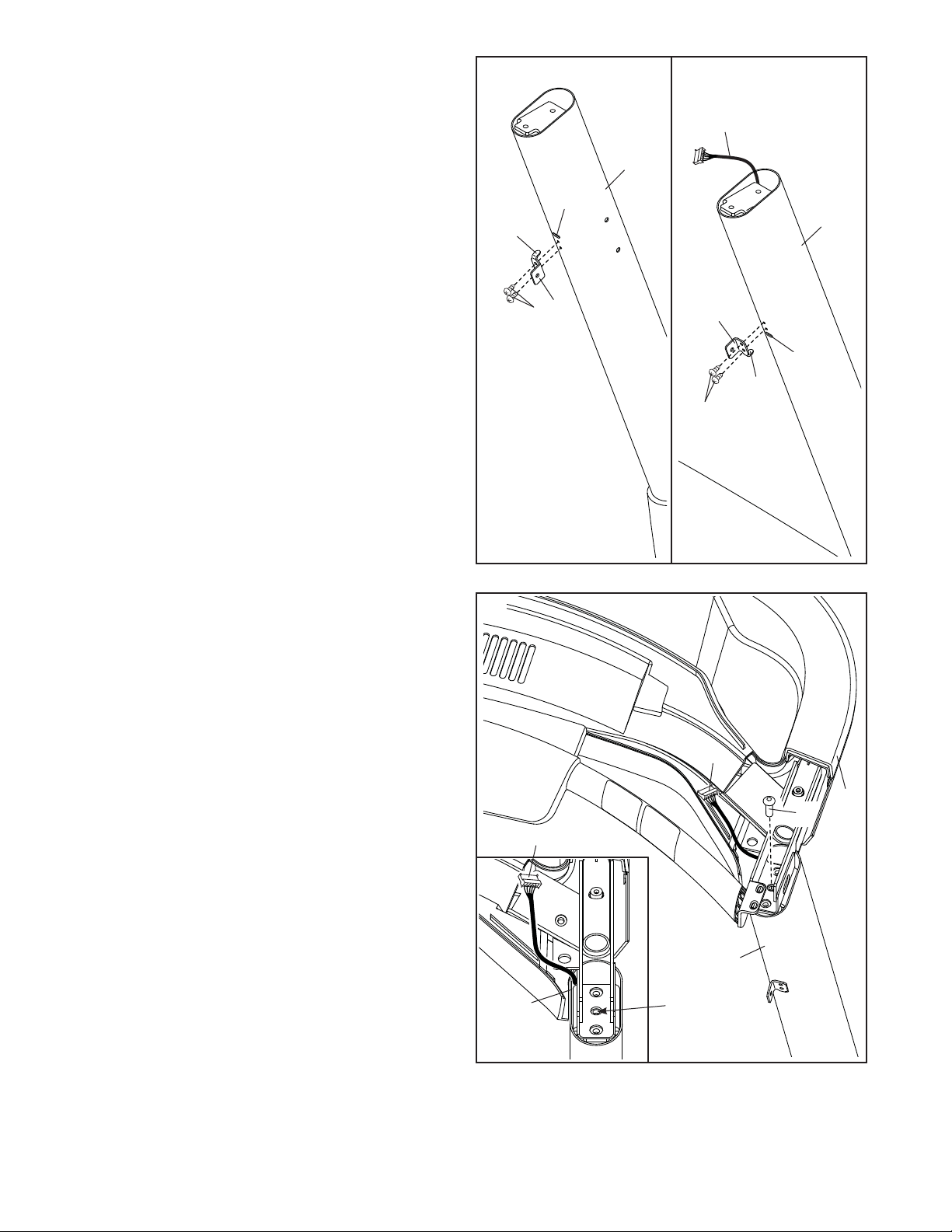
6. See the left drawing. Insert the tab (E) on one
of the Cover Brackets (18) into the slot (F) in the
Left Upright (89), and attach the Cover Bracket
with two #8 x 1/2" Screws (1).
See the right drawing. Attach the other
Cover Bracket (18) to the Right Upright (90) as
described above. Note: On the Right Upright,
the slot (F) is below the two small holes. The
Cover Bracket will need to be rotated 180º
compared to the Cover Bracket on the left
side.
Position the Upright Wire (81) to the left side of
the Right Upright (90) as shown.
E
E
81
89
90
81
90
6
7
18
18
G
F
F
1
1
81
7. With the help of a second person, set the
console base assembly (G) on the Right Upright
(90) and Left Upright (not shown). See the inset
drawing. Position the Upright Wire (81) so that it
is on the inside of the Upright as shown. Do not
pinch the Upright Wire.
Partially tighten a 5/16" x 3/4" Screw (8) into the
center hole on each side of the console base
assembly (G) and the top of the Right and Left
Uprights (90, not shown); do not fully tighten
the Screws. Note: The Screws are used only
to hold the console base assembly in place
during assembly.
Center
Hole
90
8
Loading ...
Loading ...
Loading ...