Part No. 7242352 (Rev. D 3/14/12)
ROTOR SEAL KIT INSTALLATION INSTRUCTIONS
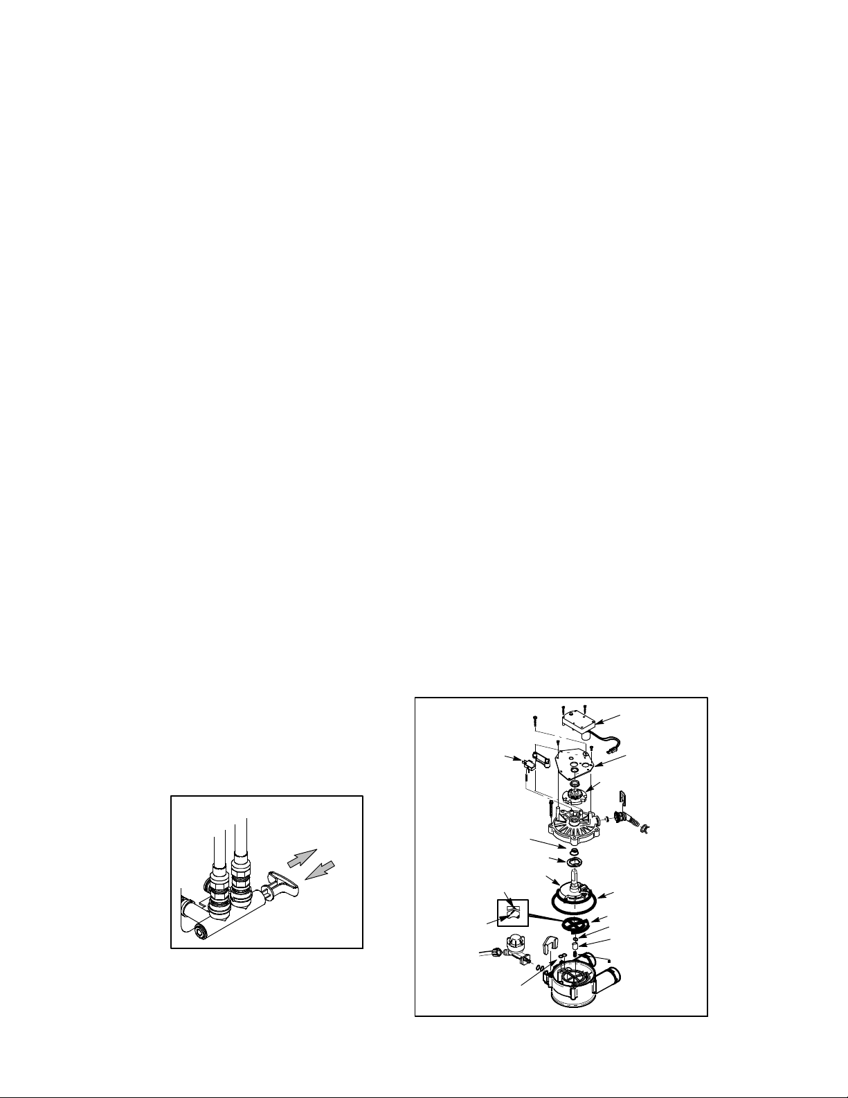
Note: Before attempting to service the valve, turn off the water supply to the unit by pushing the
bypass valve stem in for bypass (Figure 1) and unplug transformer from electrical power.
1. Loosen 3 hex head screws toward the backside of the valve, allowing pressure to bleed
out. Catch this water with a r ag.
2. Disassemble valve. To remove parts refer to the valve drawing. A Phillips screwdriver
or nut driver and pliers are the only tools needed to disassemble the valve.
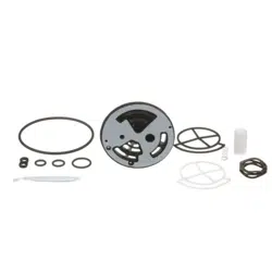
3. Remove old o--rings, rotor disc, seals, drain seal, drain plug and wave washer.
4. Be sure all parts are in place and in the proper position. Lubricate new o--r ings and
seals with the included tube of silicone grease.
5. Install rotor seal, place the seal into the valve groove, rounded side down (see cross
section in Figu re 2. Apply a light coating of silicone grease to the seals’ crossing ribs.
Then carefully center the wear strip on the seal, and push it down onto the seal.
6. Install the nozzle and venturi seal, new spring, drain plug and drain seal.
7. Slide the wave washer and the two o--rings onto the top of the rotor shaft.
8. Center the r otor into the valve body, on the rotor seal.
9. Lower the valve cover onto the valve body. Then install the cover screws. Before tight-
ening screws, install the valve cam and gear. Then, turn the rotor (clo ckwise only) to
the soft water position.
10. Tighten the valve cover screws using a criss--cross p attern. If using a torque wrench,
torque to 30 inch pounds.
11. Lubricate the gear on the motor and the cam & gear with Molycote grease or other high
quality gear lubricant. Be sure to orient the switch as shown in Figure 2, with the lever
toward the cam.
12. Slowly move the bypass valve stem towards the soft water position, pausing several
times to allow the system to pr essurize.
13. Plug the transformer into the electrical outlet.
14. To verify proper function of the softener, complete the manual advance diagnostics as
outlined in the Installation/Op eration manual.
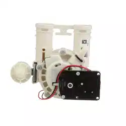
Figure 1
motor
swit ch
motor plate
cam & gear
o- ring seals
wave washer
rotor & disc
o- ring
rotor seal
drain seal
nozzle & venturi seal
seal
wear--strip
Figure 2
drain plug
spring
bypass valve
PUSH IN
for bypass
PULL OUT
for soft water