Loading ...
Loading ...
Loading ...
16
Assembly, Operation & Maintenance Instructions
*Due to ongoing design modications, support brackets may be permanently xed to the element
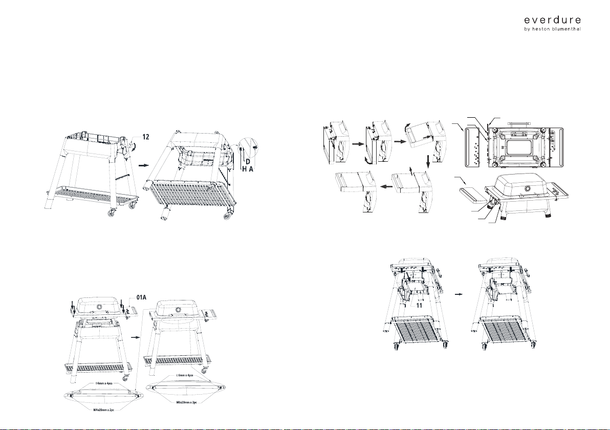
STEP 08
/ Push the at edge of the cylinder hook (12) into the slot of the stand top (above the
right hand side legs and castors) up until the dogleg, and then rotate down until the hook
is against the stand top side. Fix into place using a M6x12mm screw (A), M6 locking nut
(H) and spring washer (D). The stand is now complete.
STEP 09
/ Position the stand with the castor wheels to the right. Two people should lift the
barbeque and hood assembly (01A) by the serveries, and place it within the stand
(facing forwards, castors to the right). Fix the barbeque to the stand top with the four
M6x20mm screws and M6 spring washers removed at step 1 – two to the front and two
to the rear. Tighten fully.
STEP 10
/ To attach the left hand side servery (15) to the BBQ chassis (01B) support the left hand
side servery and align the locating tabs to the keyholes and slide the left hand servery
backwards (approximately 1cm). Fit Spring (J) onto M6 x 85mm Screw (I) and secure
with M6 Nut (H).
STEP 11
/ Fit the fat tray (11) and disposable foil tray into the brackets at the bottom of the
barbeque. Take care that the fat tray is allocated correctly.
STEP 12
/ Place the grills onto the barbeque as shown in the diagrams. Each grill should have a
5-6mm gap around each edge. Each grill will allocate in a groove on a plate support.
H
J
I
15
H
J
I
15
Loading ...
Loading ...
Loading ...