Reference Manual
© 2023 Roland Corporation
01
2
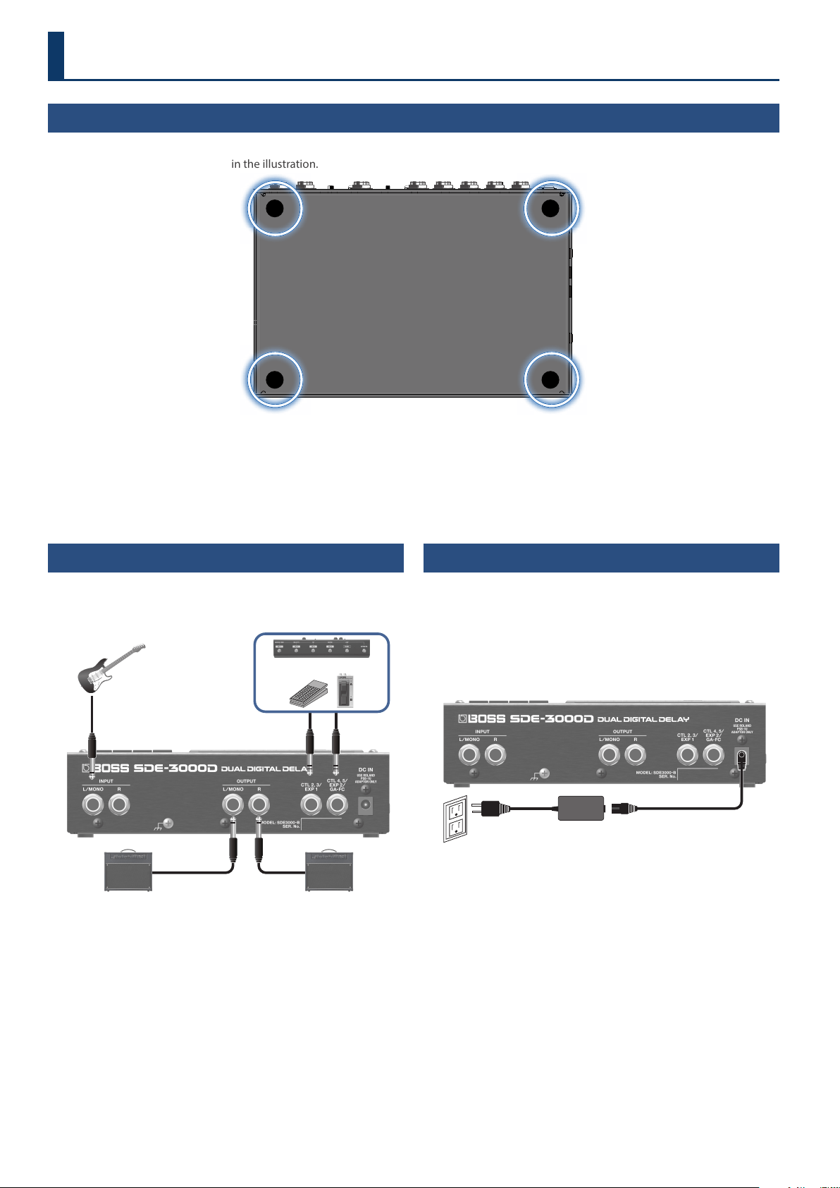
Connecting the Equipment
* To prevent malfunction and equipment failure, always turn
down the volume, and turn o all the units before making any
connections.
CTL 4, 5 jacks only (for the GA-FC)
INPUT
CTL 2, 3
EXP 1
OUTPUT ROUTPUT L
CTL 4, 5
EXP 2
GA-FC
There are many other ways to connect the SDE-3000D.
For details, refer to “Connecting an Amp and Conguring the Input/
Output Settings” (p. 9).
Turning the Power On
* Before turning the unit on/o, always be sure to turn the volume
down. Even with the volume turned down, you might hear some
sound when switching the unit on/o. However, this is normal and
does not indicate a malfunction.
1. Connect the AC adaptor to the DC IN jack.
This turns the power of the SDE-3000D on.
DC IN
AC adaptor
2. Turn on any connected devices rst, and then turn on
your guitar amp.
* Do this in reverse order when turning o the power.
* Unsaved data is lost when the power turns o. You must save any
data in advance that you want to keep.
* The bank and memory number that you were using when you
turned the power o are stored in memory, and are recalled when
you turn the unit back on.
Getting Ready
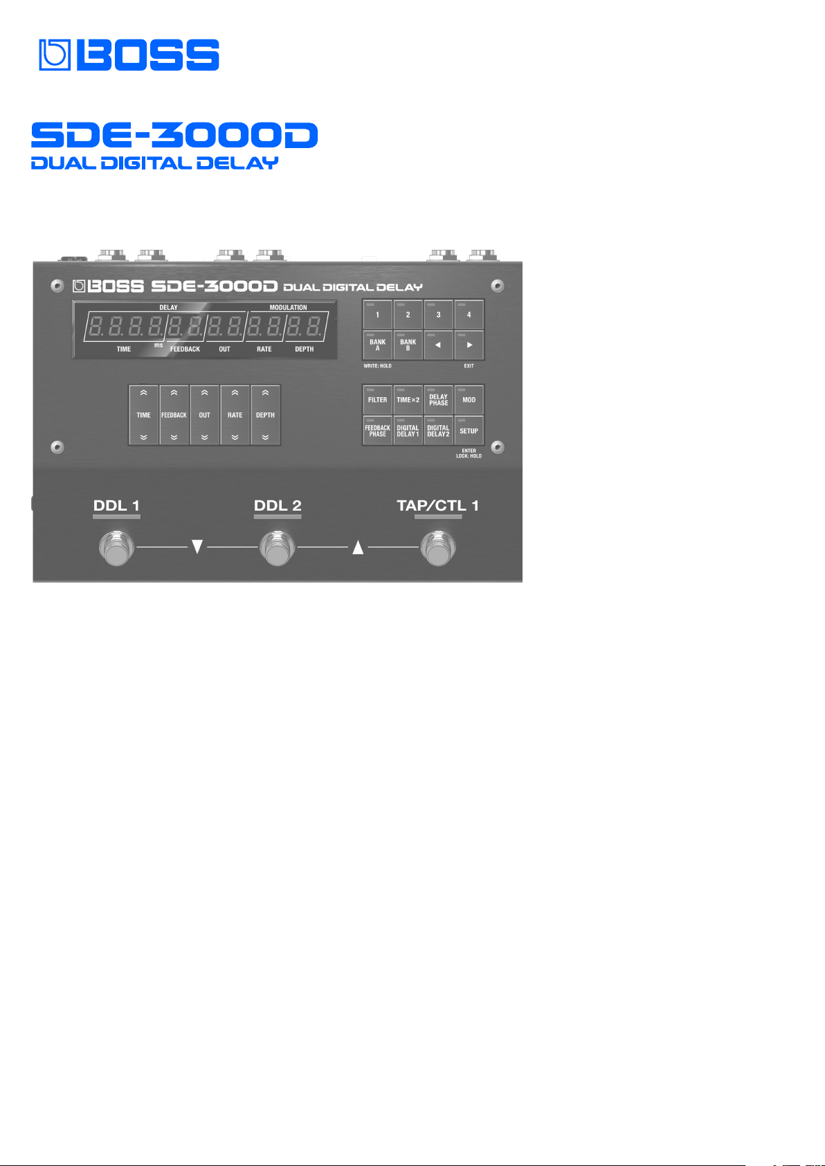
Attaching the Rubber Feet
You can attach the rubber feet (included) if necessary.
Attach them in the locations shown in the illustration.
* Using the unit without rubber feet may damage the oor.
* When turning the unit over, be careful so as to protect the buttons and knobs from damage. Also, handle the unit carefully; do not drop it.
3
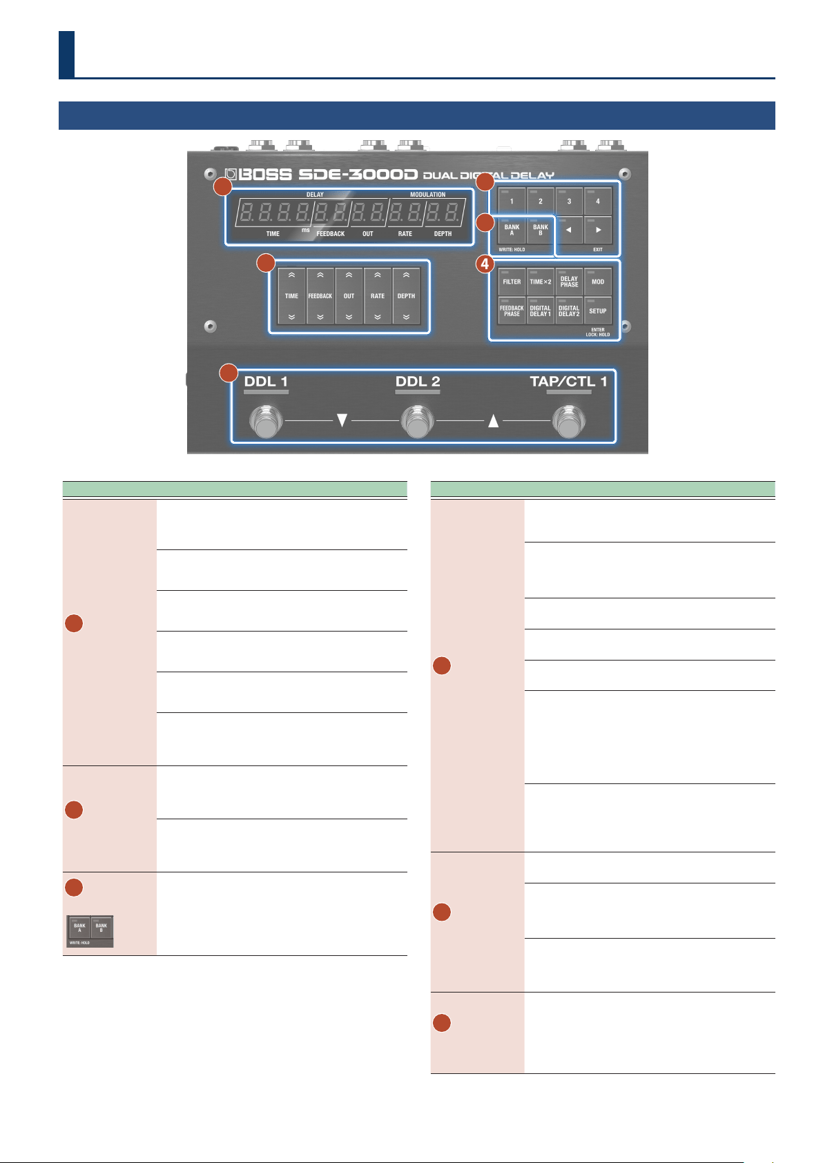
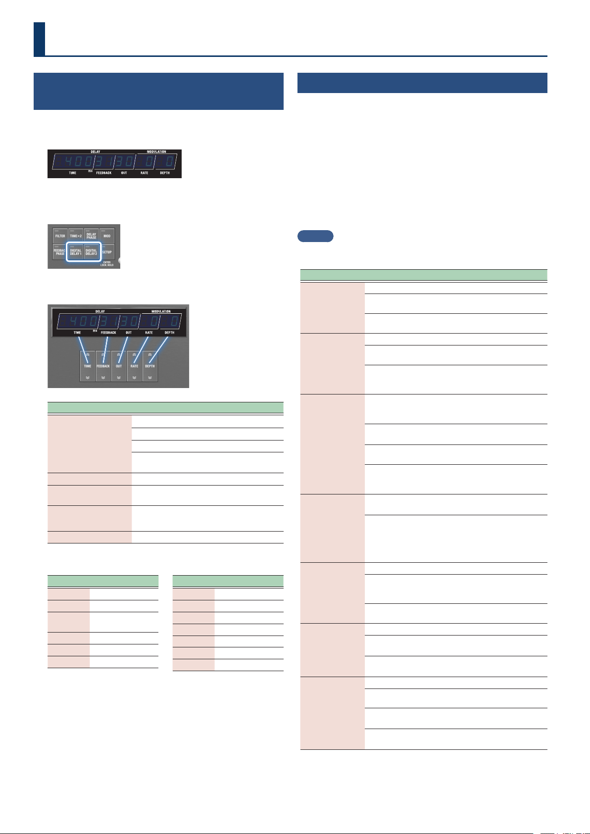
Top Panel
1
5
6
4
2
3
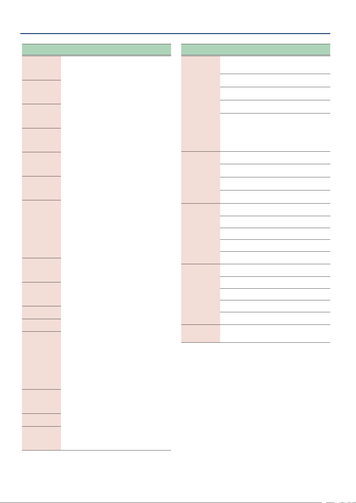
Area Explanation
1
Controls
Press the top part of each button to increase the value, and
press the bottom part of each button to decrease the value.
Long-press a button to make its value change rapidly.
[TIME] buttons
Adjusts the delay time.
[FEEDBACK] buttons
Adjusts the delay feedback level.
[OUT] buttons
Adjusts the output level for the delay sound.
[RATE] buttons
Adjusts the cycle of the delay modulation.
[DEPTH] buttons
Adjusts the depth of the delay modulation.
A setting of zero turns the modulation o.
2
Memory
[1]–[4] buttons
Selects the memories.
Ø
“Selecting a Memory” (p. 15)
[ã] [â] buttons
Switches the play screen in the following order: Input
level Õ Parameter Õ Tempo Õ Bank/memory
3
Bank
[BANK A] [BANK B] buttons
Switches between banks A and B.
You can select the bank C memories (C.01 and up) by
using your feet (p. 6).
Area Explanation
4
Delay settings
[FILTER] button
A delay lter. This gives you a natural-sounding eect
when you’re using the delay as an echo.
[TIME×2] button
Switches between delay time ranges.
O (×1): 0.0-1500 ms
On (×2): 0.0-3000 ms
[DELAY PHASE] button
Inverts the phase of the delay sound.
[MOD] button
Turns the modulation on/o.
[FEEDBACK PHASE] button
Inverts the phase of the delay sound’s feedback.
[DIGITAL DELAY 1] button (DDL 1) /
[DIGITAL DELAY 2] button (DDL 2)
Switches between the DDL 1 and DDL 2 parameter
displays.
When TIME LINK is OFF or OFFSET, you can switch
between time displays for the L channel (lights up
green) and the R channel (lights up red) of DDL 1/DDL 2.
[SETUP] button
Congures the memory and system settings. Long-
press the button to turn the lock on/o. Other button
operations are disabled when the lock feature is
enabled.
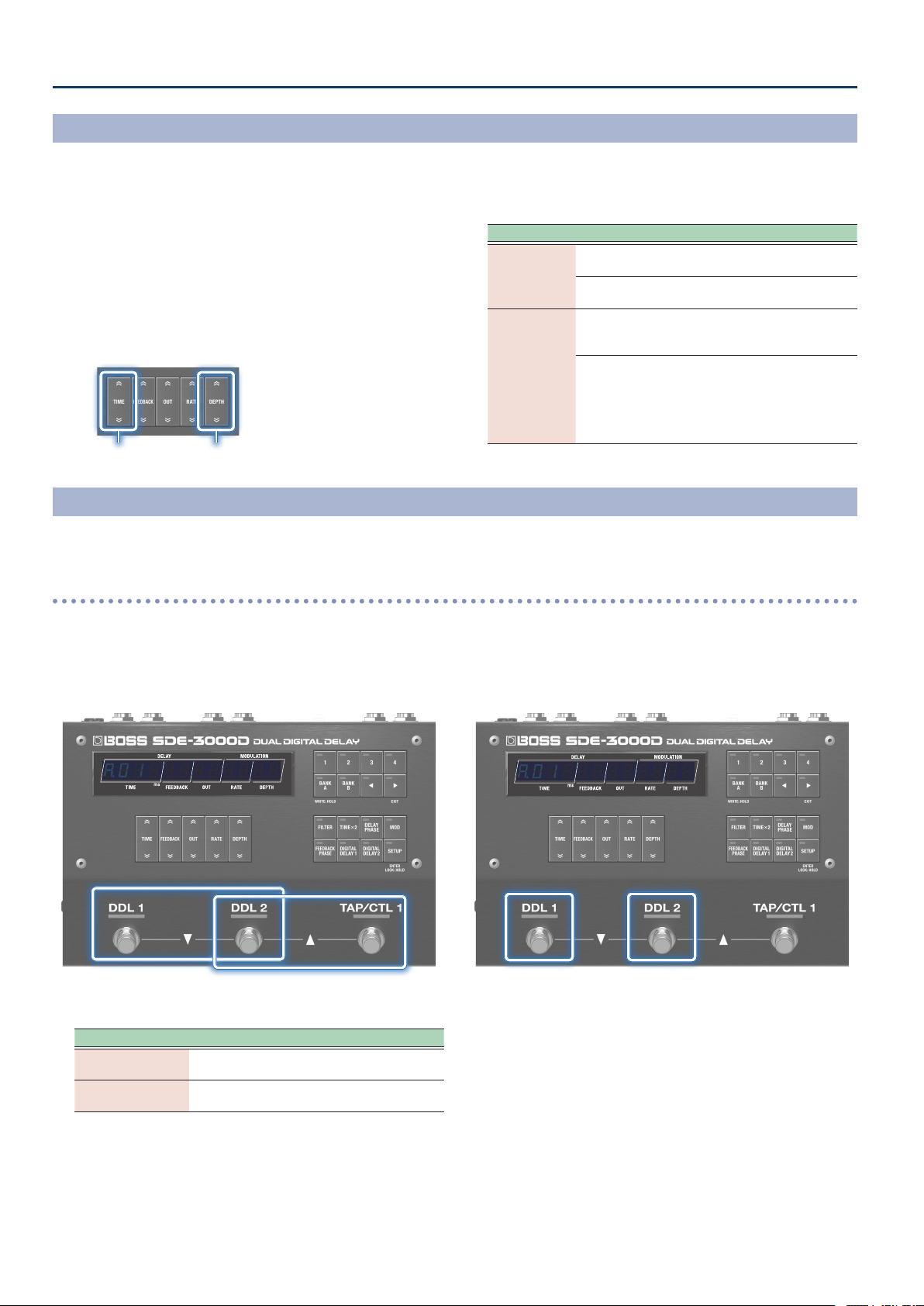
5
Switches
[DDL 1] switch / [DDL 2] switch
Switches the DIGITAL DELAY 1/2 on and o.
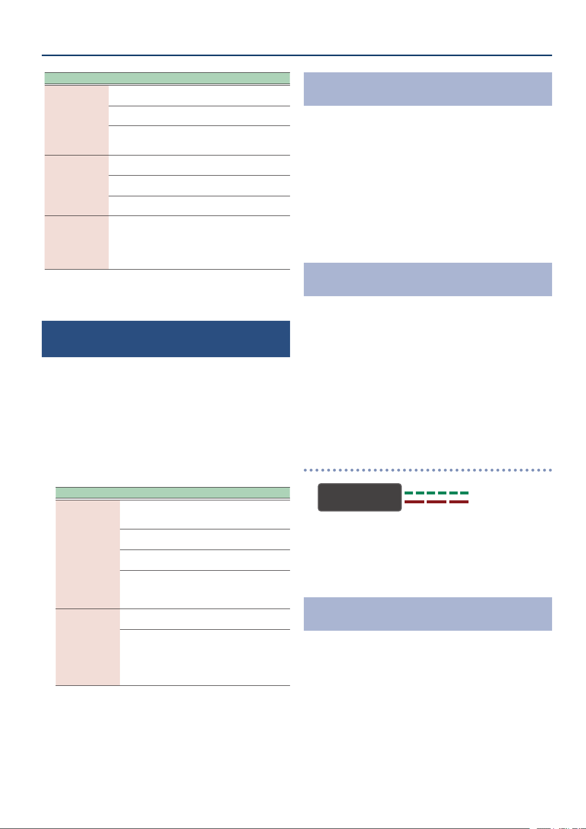
[TAP/CTL 1] switch
Press this switch in specic intervals to set the delay
time. Also, use this for the CTL function and assign
setting functions.
You can select memories by pressing the [DDL 1] switch and
[DDL 2] switch at the same time, or by pressing the [DDL 2]
switch and [TAP/CTL 1] switch at the same time.
Ø“Selecting Memories via Foot Control” (p. 6)
6
Display
This shows various information depending on the operation.
Play screen
Ø “Switching Between Play Screen Displays” (p. 4)
Edit screen
Ø See the edit pages for details.
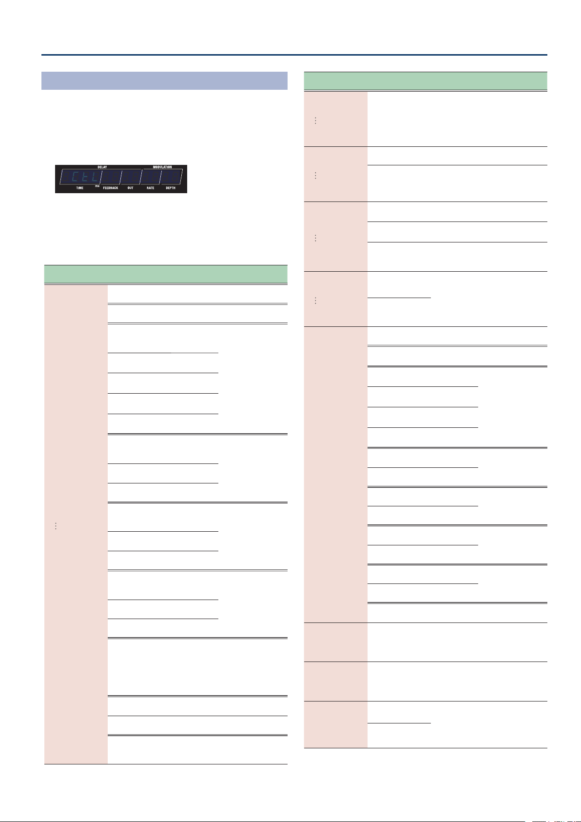
Panel Descriptions
4
Getting Ready
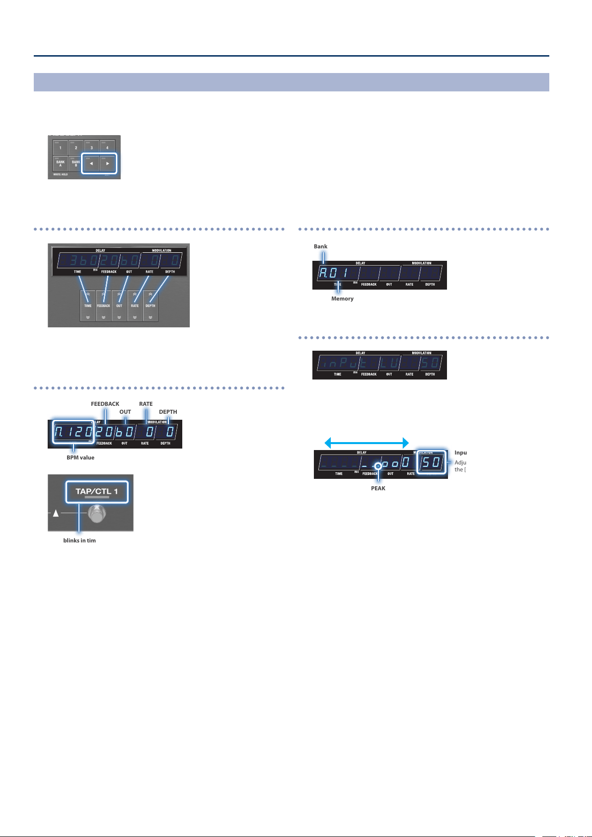
Parameter display
¸¸¸¸¸¸¸¸¸¸¸¸$3ļ020ļ0$0$0
The values you set using the control buttons are all displayed here.
BPM display
¸¸¸¸¸¸¸¸¸¸¸¸ŷ12020ļ0$0$0
BPM value
FEEDBACK
OUT
RATE
DEPTH
This blinks in time with the BPM (default setting).
You can change the function that’s controlled by the [TAP/CLT 1] switch.
For details, refer to “Conguring the CTL Function (CTL)” (p. 25).
Bank/memory display
¸¸¸¸¸¸¸¸¸¸¸¸Ʒ01
Bank
Memory
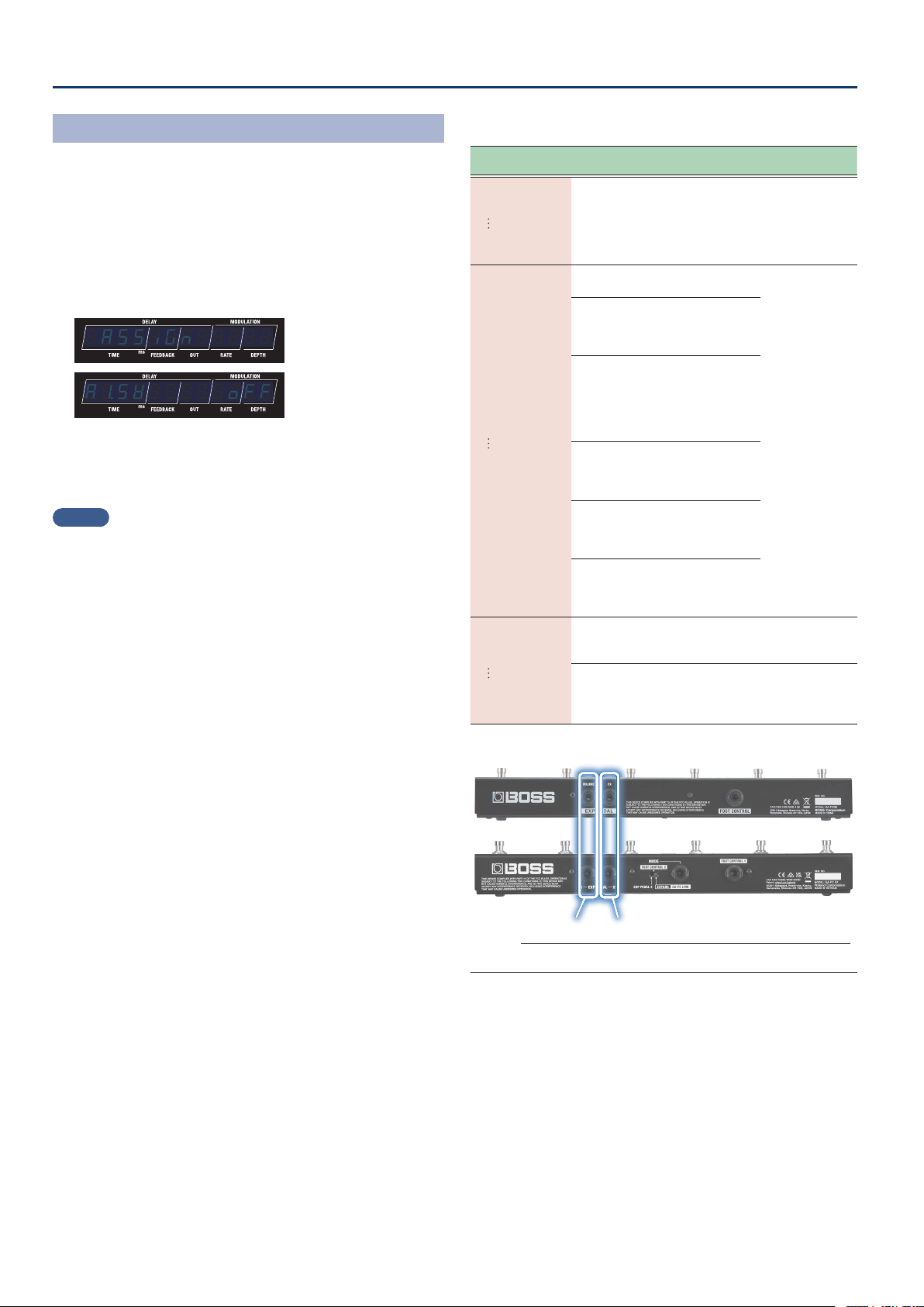
Input level meter display
¸¸¸¸¸¸¸¸¸¸¸¸inPvt$LU$$50
INPUT LV is indicated, and the unit automatically switches to
showing the input level.
The meter moves according to the input signal level.
¸¸¸¸¸¸¸¸¸¸¸¸_____ňooO$50
Volume down Volume up
PEAK
When the input signal exceeds this level, the sound begins to distort.
Input level
Adjust the value with
the [DEPTH] buttons.
* The input level setting is the same for all memories (system
setting).
Switching Between Play Screen Displays
The screen that appears after you turn on the power is called the “play screen”.
1. Press the [ã] [â] buttons to switch between displays.
Input level display Õ parameter display Õ BPM display Õ bank/memory display
5
Panel Descriptions
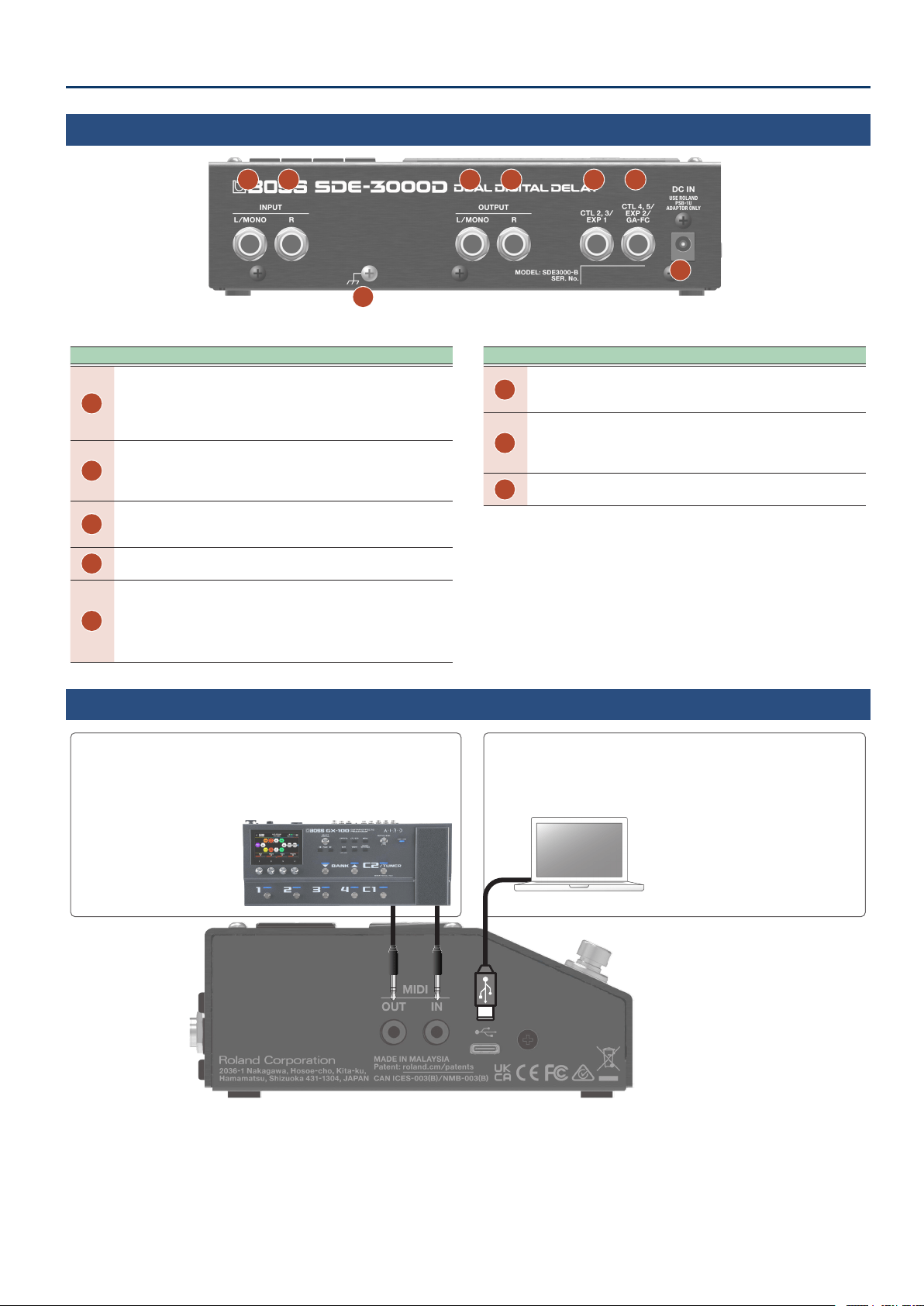
Rear Panel
C F E D
A B
G
H
Area Explanation
A
INPUT L/MONO jack
Connect your guitar or keyboard here.
For a mono connection, use only the L/MONO jack.
If the unit is set for stereo input, use this to input the L channel
audio.
B
INPUT R jack
When you connect a device to this jack, the L/R jack pair
automatically switches to stereo input. In this case, this jack is used
to input the R (right) channel.
C
OUTPUT L/MONO jack
Connect this to your guitar amp, mixer or other audio equipment.
For a mono output, connect only to the L/MONO jack.
D
OUTPUT R jack
Connect this to your guitar amp, mixer or other audio equipment.
E
CTL 2, 3/EXP 1 jack
You can connect an expression pedal
(*1)
or footswitches
(*2)
to these
jacks for controlling a variety of parameters.
* Use only the specied expression pedal. By connecting any other expression
pedals, you risk causing malfunction and/or damage to the unit.
* For more about footswitch settings, refer to “Connecting Footswitches” (p. 24).
Area Explanation
F
CTL4, 5/EXP2/GA-FC jack
You can connect an expression pedal
(*1)
or footswitches
(*2)
and foot
controllers
(*3)
to these jacks for controlling a variety of parameters.
G
DC IN jack
Connect the AC adaptor here.
The SDE-3000D powers up when the AC adaptor is connected to the
DC IN jack.
H
Ground terminal
Connect this to an external earth or ground if necessary.
*1 Expression pedal
Sold separately: EV-30, FV-500L, FV-500H, Roland EV-5
*2 Footswitch
Sold separately: FS-5U, FS-5L, FS-6, FS-7
*3 Foot controller
Sold separately: GA-FC, GA-FC EX
Side Panel
USB port (USB Type-C
®
)
Connect your computer using a commercially available USB cable that
supports USB 2.0.
Ø “Connecting to a Computer” (p. 34)
* Do not use a USB cable that is designed only
for charging a device. Charge-only cables
cannot transmit data.
MIDI (OUT/IN) jacks
Use TRS/TRS or TRS/MIDI connecting cables to connect this unit to an
external MIDI device.
Ø “Connecting with an External MIDI Device” (p. 31)
Sold separately:
TRS/TRS connecting cable
BCC-1-3535, BCC-2-3535
TRS/MIDI connecting cable
BMIDI-5-35, BMIDI-1-35, BMIDI-2-35
6
Panel Descriptions
1. Select a memory.
Selects the previous memory
(memory decrement)
Selects the next memory
(memory increment)
¸¸¸¸¸¸¸¸¸¸¸¸
Ʒ01
Action Operation
Select the previous
memory
[DDL 1] switch + [DDL 2] switch
Select the next
memory
[DDL 2] switch + [TAP/CTL 1] switch
2. The [DDL 1] switch turns DDL 1 on/o, and the [DDL 2]
switch turns DDL 2 on/o.
DDL 1 on/o DDL 2 on/o
¸¸¸¸¸¸¸¸¸¸¸¸
Ʒ01
Selecting Memories via Foot Control
The SDE-3000D has 100 memories, and you can select the memories via foot control.
Memories: A.01–A.04, B.01–B.04, C.01–C.92
Manual mode
In this mode, the 100 memories are called up in sequential order, one by one.
Conguring the Footswitch Mode
The footswitch mode features a “manual mode” in which you can select one memory at a time in order, and “memory mode” in which you can
select two memories at a time in order. Further, memory mode features an “immediate” mode that lets you select odd-numbered memories, and a
“wait” mode that lets you show two memories and then select the memory.
1. Press the [SETUP] button.
2. Use the [TIME] buttons to select “SYSTENSYSTEN”, and press
the [SETUP] (ENTER) button.
3. Use the [TIME] buttons to select the “FS.NdFS.Nd” and
“ŷNodŷNod” parameters, and then use the [DEPTH] buttons
to change the value.
Select the parameter Edit the value
Parameter Value Explanation
FS.Nd
(Footswitch Mode)
NAnvAL
(Manual)
Manual mode.
Selects one memory at a time.
NENory
(Memory)
Memory mode.
Selects two memories at a time.
ŷNod
(M. Mode)
iNNEdit
(immediate)
Immediate.
Switches immediately to the memory
after the next in memory mode.
ľAit
(Wait)
Wait.
In memory mode, when two
memories are displayed via foot
control, the memory switches only
when you operate a foot control once
more.
7
Panel Descriptions
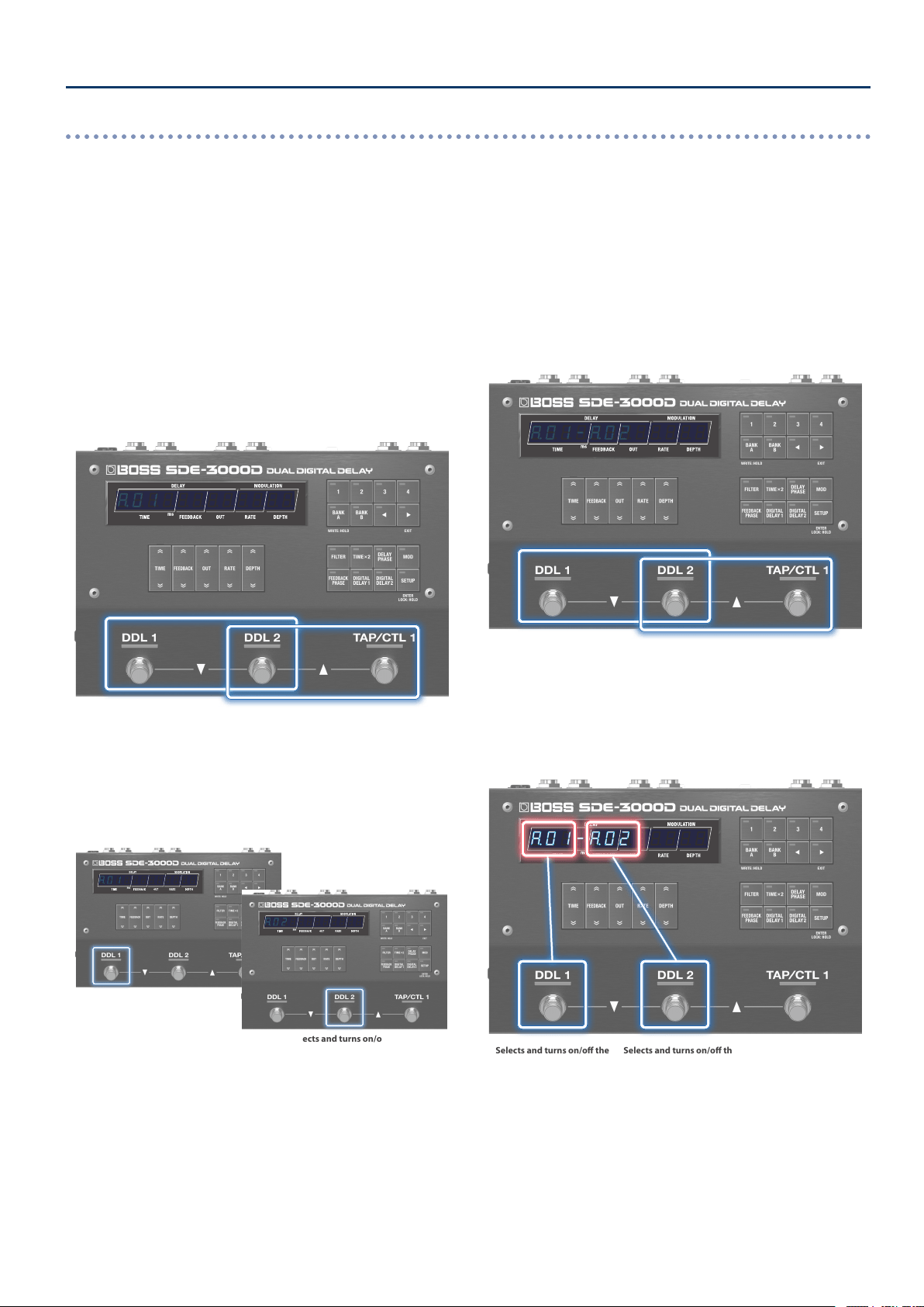
Immediate
Switches to odd-numbered memories, two at a time. To select an
even-numbered memory, press the [DDL 2] switch.
1. Select a memory.
[DDL 1] switch + [DDL 2] switch: previous memory
[DDL 2] switch + [TAP/CTL 1] switch: next memory
This immediately switches to the next two memories.
For instance, when
A.01 is selected, the [DDL 1] switch selects and
turns on/o the delay for A.01 (odd-numbered memories), and the
[DDL 2] switch selects and turns on/o the delay for A.02 (the even-
numbered memories).
Selects the previous memory
(memory decrement)
Selects the next memory
(memory increment)
¸¸¸¸¸¸¸¸¸¸¸¸
Ʒ01
2. Select the memories using the [DDL 1] and [DDL 2]
switches.
If you press the same switch twice in a row, you can turn the delay
o or restore the memory to its stored state.
¸¸¸¸¸¸¸¸¸¸¸¸
Ʒ01
Selects and turns on/o the
even-numbered memories
¸¸¸¸¸¸¸¸¸¸¸¸
Ʒ02
3. To turn the delay o, press the same switch again.
Wait
This displays two memories at a time for you to select.
1. Switch the memory display.
[DDL 1] switch + [DDL 2] switch: previous memory
[DDL 2] switch + [TAP/CTL 1] switch: next memory
The display changes with each operation. The memory does not
switch until you perform the next operation.
Selects the previous memory
(memory decrement)
Selects the next memory
(memory increment)
¸¸¸¸¸¸¸¸¸¸¸¸
Ʒ01-Ʒ02
2. Select the memories using the [DDL 1] and [DDL 2]
switches.
If you press the same switch twice in a row, you can turn the delay
o or restore the memory to its stored state.
Selects and turns on/o the
odd-numbered memories
Selects and turns on/o the
even-numbered memories
¸¸¸¸¸¸¸¸¸¸¸¸
Ʒ01-Ʒ02
3. To turn the delay o, press the same switch again.
Memory mode
In this mode, the 100 memories are selected in sequential order, two at a time.
Further, this mode features an “immediate” mode that lets you select odd-numbered memories, and a “wait” mode that lets you show two
memories and then select a memory.
8
Conguring the Input and Output Settings
Conguring the Input/Output to Match the
Connected Device
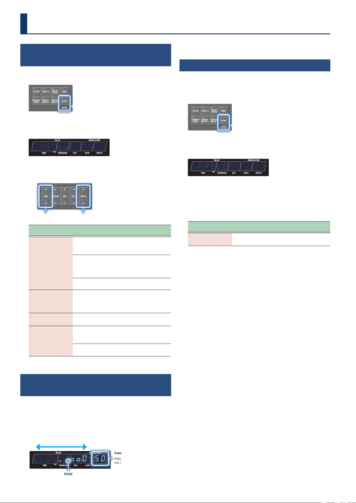
1. Press the [SETUP] button.
2. Use the [TIME] buttons to select “in;ovtin;ovt”, and press
the [SETUP] (ENTER) button.
¸¸¸¸¸¸¸¸¸¸¸¸;in;ovt
3. Use the [TIME] buttons to select a parameter, and then
use the [DEPTH] buttons to change the value.
Select the parameter Edit the value
Parameter
[TIME] buttons
Value
[DEPTH] buttons
Explanation
ovt
(Output Setting)
StErEoStErEo
(STEREO)
The sound is output in stereo
from the OUTPUT L/MONO and
R jacks.
diƐEFödiƐEFö
(L: DIRECT, R: EFX)
The direct sound is output from
the OUTPUT DIRECT jack, and
the delay sound is output from
the OUTPUT EFX L jack.
diƐNvtEdiƐNvtE
(DIRECT MUTE)
Mutes the direct sound.
vniGAin
(Uni Gain)
4d4d, -10d-10d,
-20d-20d
Switches between +4 dBm,
-10 dBm and -20 dBm to match
the input/output level of the
connected device.
iƔUol
(Input Volume)
11–100100
Adjusts the input level.
bYPASS
(Bypass)
DSPDSP
(DSP)
This fully recreates the bypass
characteristics of the original
Roland SDE-3000.
AnLGAnLG
(Analog)
Outputs via a hardware bypass
signal route.
Adjusting the Input Level While Checking the
Level Meter
1. On the play screen (the screen that appears right after
you start up the unit), press the [ã] button to show the
input level meter.
Input level meter display
¸¸¸¸¸¸¸¸¸¸¸¸_____ňooO$50
Volume down Volume up
PEAK
When the input signal exceeds this level, the sound begins to distort.
Input level
Adjust the value with
the [DEPTH] buttons.
2. Use the DEPTH buttons to adjust the input level.
Adjusting the Output Level
(Output Gain)
To adjust the output level, change this value within a range of -12 to
+12 dB.
1. Press the [SETUP] button.
2. Use the [TIME] buttons to select “NASTERNASTER”, and press
the [SETUP] (ENTER) button.
¸¸¸¸¸¸¸¸¸¸¸¸$NASTER
3. Use the [TIME] buttons to select “ovƸGAinovƸGAin”, and then
use the [DEPTH] buttons to change the value.
Output gain parameters
(in MASTER settings)
Parameter
[TIME] buttons
Value
[DEPTH] buttons
Explanation
ovƸGAin
(Output Gain)
-12-12–1212
Adjusts the output level.
9
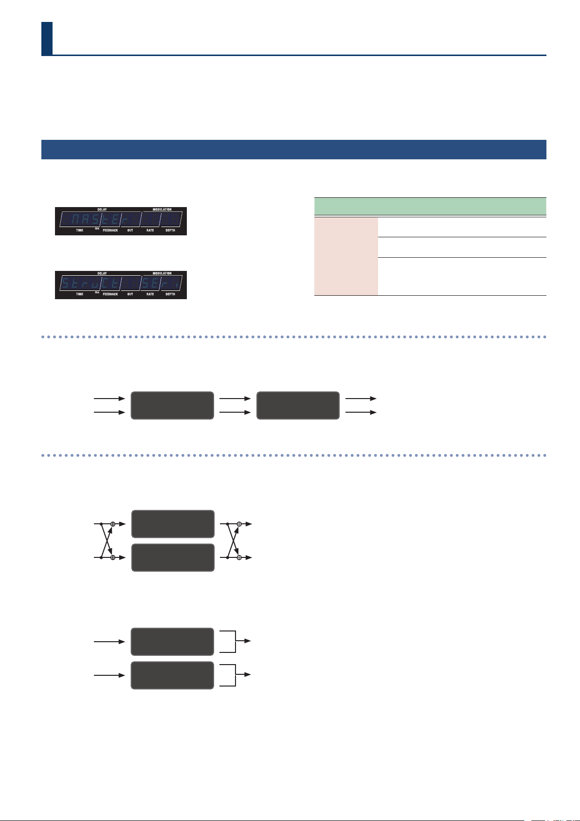
The SDE-3000D has two built-in digital delays (Roland SDE-3000) that have been expanded to work in stereo.
You can switch the conguration of these two delays between serial to parallel. The connection method is called a “structure”.
For details on how to congure the input/output settings, refer to the information below.
Ø “Conguring the Input and Output Settings” (p. 8)
Switching Between Serial and Parallel Connections
(Structure)
1. Press the [SETUP] button.
2. Use the [TIME] buttons to select “NASTERNASTER”.
¸¸¸¸¸¸¸¸¸¸¸¸$NASTER
3. Press the [SETUP] (ENTER) button.
¸¸¸¸¸¸¸¸¸¸¸¸StrvCt$$SEri
4. Use the [TIME] buttons to select “StrvCtStrvCt”, and then
use the [DEPTH] buttons to change the value.
Parameter
[TIME] buttons
Value
[DEPTH] buttons
Explanation
StrvCt
(Structure)
SEriSEri
(Series)
The two delays are connected
in series.
PARA1PARA1
(Parallel 1)
The two delays are connected
in parallel.
PARA2PARA2
(Parallel 2)
Outputs the sound
independently from the two
delays via the OUTPUT L/MONO
and R jacks.
Connected in series
(serial)
In series
The two delays are connected in series.
DDL 1 (L/R) DDL 2 (L/R)
INPUT L OUTPUT L
INPUT R OUTPUT R
Parallel connection
Parallel 1
The two delays are connected in parallel.
DDL 1 (L/R)
DDL 2 (L/R)
INPUT L
INPUT R
OUTPUT L
OUTPUT R
Parallel 2
Outputs the sound independently from the two delays via the OUTPUT L/MONO and R jacks.
DDL 1 (L/R)
INPUT L OUTPUT L
DDL 2 (L/R)
INPUT R OUTPUT R
Connecting an Amp and Conguring the Input/Output Settings
10
Connecting an Amp and Conguring the Input/Output Settings
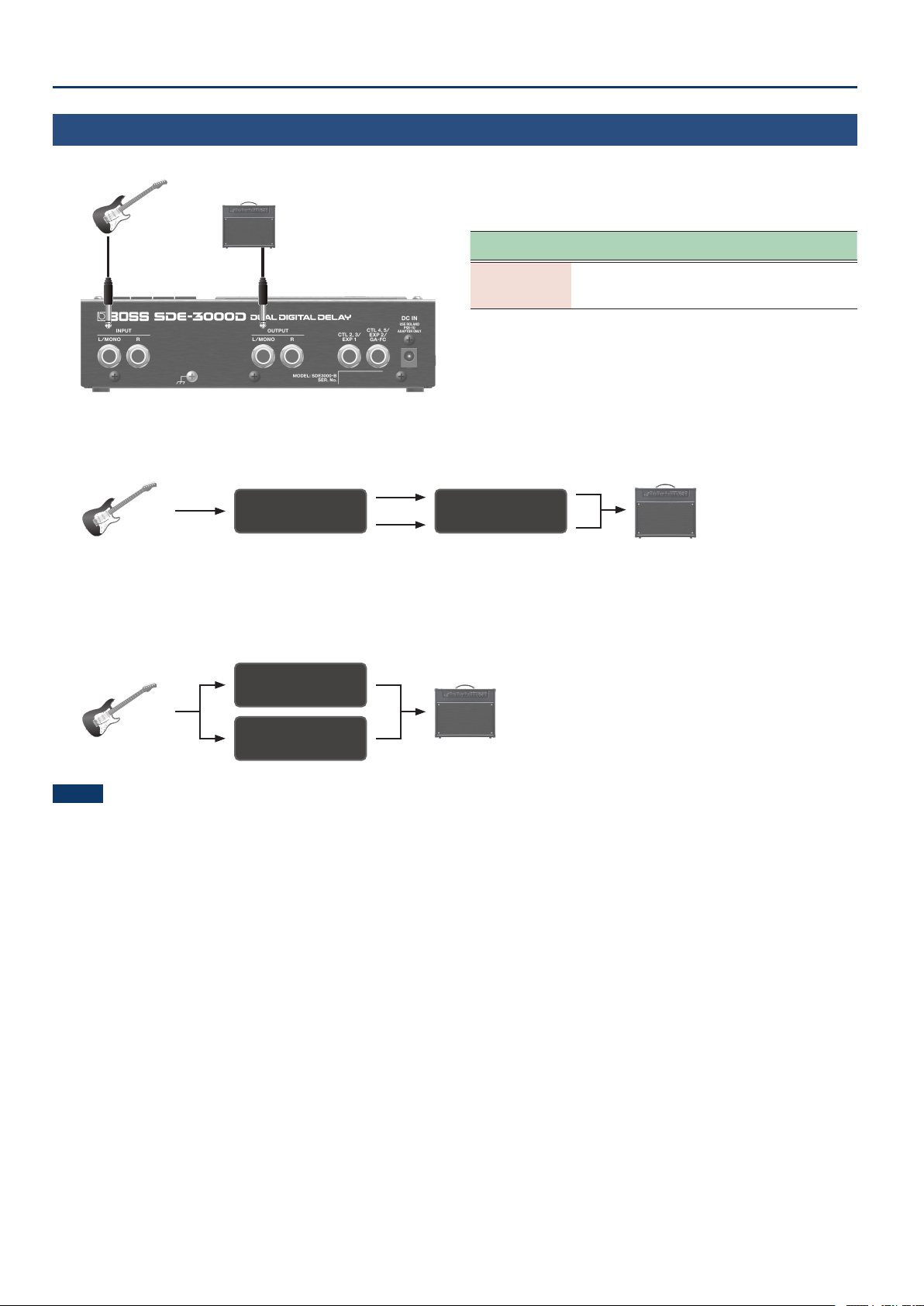
Using a Single Amp
(1-in, 1-out)
Use the OUTPUT L/MONO jack when connecting to only one amp. The dry (direct) and wet (delay) sounds are mixed when output.
INPUT
L/MONO
IN OUT settings
[SETUP] Ó “in;ovt”
Parameter
[TIME] buttons
Value
[DEPTH] buttons
Explanation
ovt
(Output Setting)
StErEoStErEo
(STEREO)
The sound is output in mono when
an amp is only connected to the
OUTPUT L/MONO jack.
Delay structure
(in series: connected one after another)
The two delays are connected in series.
DDL 1 (L/R) DDL 2 (L/R)
Guitar AMP
DRY+WET
Delay structure
(parallel 1/2: connected separately in parallel)
The two delays are connected in parallel.
You can combine the two delays with dierent delay times to create your own sound.
DRY+WET
Guitar AMP
DDL 1 (L/R)
DDL 2 (L/R)
NOTE
The SDE-3000D fully recreates the bypass characteristics of the original Roland SDE-3000. Since the original sound is faithfully recreated by
varying the delay times and so on, you may notice a unique modulated sound that occurs with certain settings when you mix two delays that are
connected in parallel and output them in mono. This is not a malfunction.
11
Connecting an Amp and Conguring the Input/Output Settings
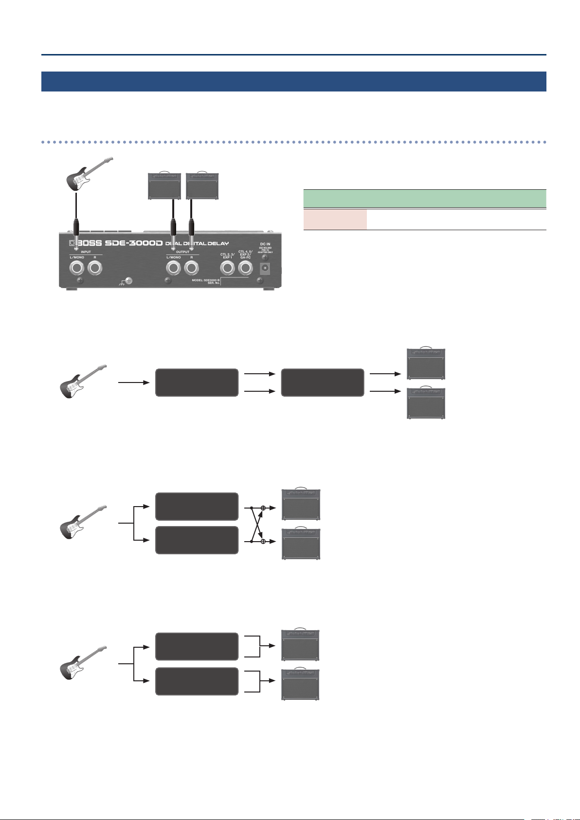
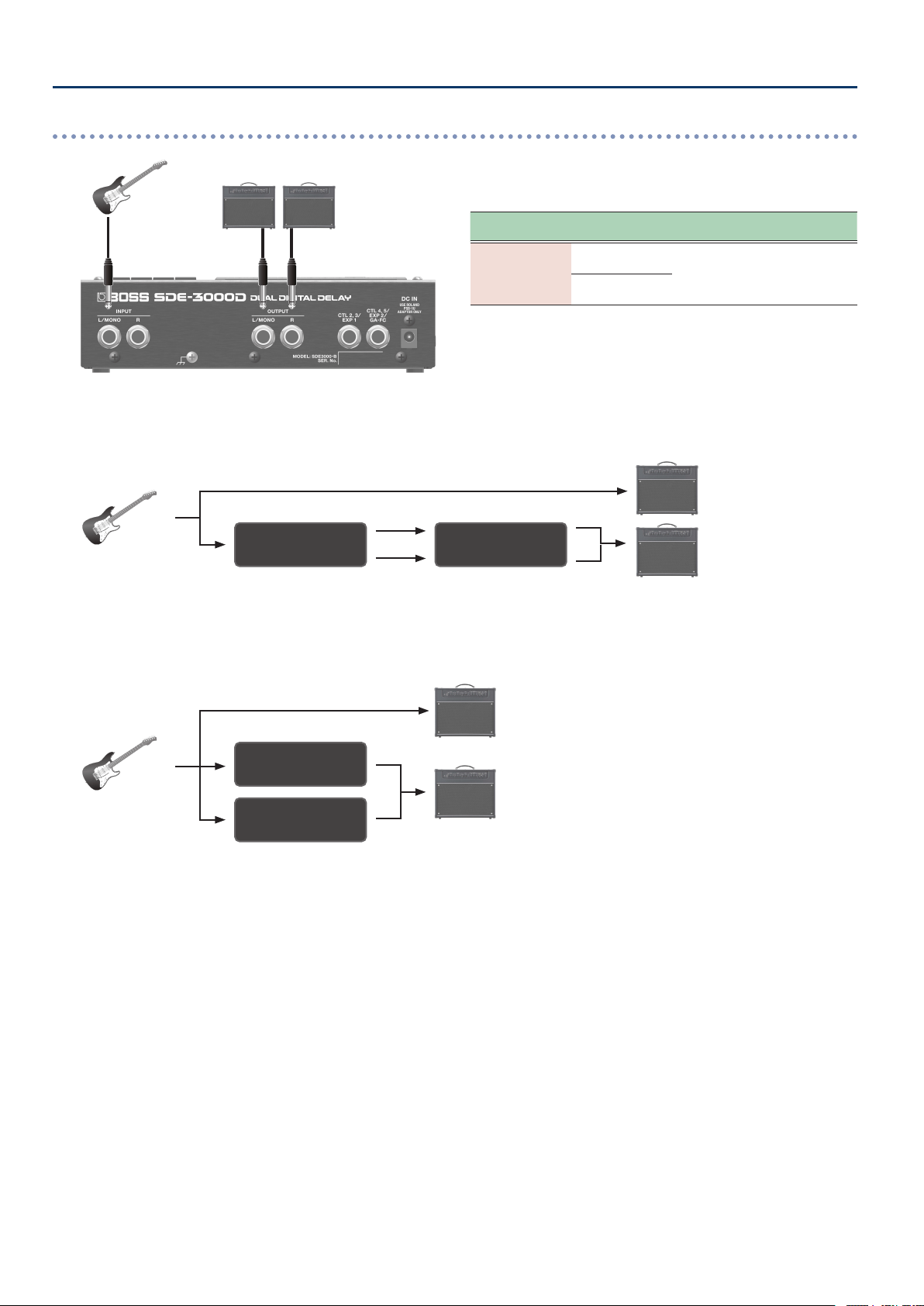
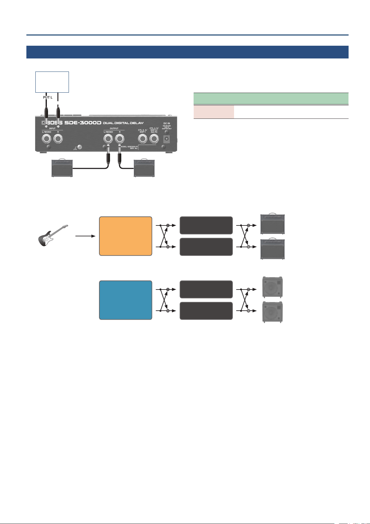
Using Two Amps
(1-in, 2-out)
Use the OUTPUT L/MONO and OUTPUT R jacks when connecting to two amps. This lets you mix the dry (direct) and wet (delay) sounds for output,
or output the dry and wet sounds separately.
When mixing the dry and wet sounds for output
INPUT
L/MONO R
IN OUT settings
[SETUP] Ó “in;ovt”
Parameter
[TIME] buttons
Value
[DEPTH] buttons
Explanation
ovt
(Output Setting)
StErEoStErEo
(STEREO)
The sound is output in stereo from
the OUTPUT L/MONO and R jacks.
Delay structure
(in series: connected one after another)
The two delays are connected in series.
DRY+WET L
DRY+WET R
Guitar
AMP
DDL 1 (L/R) DDL 2 (L/R)
Delay structure
(parallel 1: connected separately in parallel)
The two delays are connected in parallel.
DRY+WET L
DRY+WET R
Guitar
AMP
DDL 1 (L/R)
DDL 2 (L/R)
Delay structure
(parallel 2: connected separately in parallel)
The two delays are connected in parallel and output to dierent jacks.
DRY+WET L
DRY+WET R
Guitar
AMP
DDL 1 (L/R)
DDL 2 (L/R)
12
Connecting an Amp and Conguring the Input/Output Settings
When outputting the dry and wet sounds separately
INPUT
L/MONO R
IN OUT settings
[SETUP] Ó “in;ovt”
Parameter
[TIME] buttons
Value
[DEPTH] buttons
Explanation
ovt
(Output Setting)
diƐEFödiƐEFö
(L: DIRECT, R: EFX)
The direct sound is output from
the OUTPUT L/MONO jack, and
the delay sound is output from the
OUTPUT R jack.
diƐNutEdiƐNutE
(Direct Mute)
Delay structure
(in series: connected one after another)
The two delays are connected in series.
DRY
WET
Guitar
AMP
DDL 1 (L/R) DDL 2 (L/R)
Delay structure
(parallel 1/2: connected separately in parallel)
The two delays are connected in parallel and output to dierent jacks.
DRY
WET
Guitar
AMP
DDL 1 (L/R)
DDL 2 (L/R)
13
Connecting an Amp and Conguring the Input/Output Settings
Stereo Input/Output
(2-in, 2-out)
For stereo input, the dry (direct) and wet (delay) sounds are mixed when output.
INPUT L
INPUT R
RL/MONO
Eect,
keyboard,
audio device
IN OUT settings
[SETUP] Ó “in;ovt”
Parameter
[TIME] buttons
Value
[DEPTH] buttons
Explanation
ovt
(Output Setting)
StErEoStErEo
(STEREO)
The sound is output in stereo from
the OUTPUT L/MONO and R jacks.
Delay structure
(parallel 1: connected separately in parallel)
The two delays are connected in parallel.
DRY+WET L
DRY+WET R
Guitar
AMP
Stereo Eect
DDL 1 (L/R)
DDL 2 (L/R)
DRY+WET L
DRY+WET R
AMP
Keyboard
or
Audio Player
DDL 1 (L/R)
DDL 2 (L/R)
14
Using the Foot Volume
Conguring the Foot Volume
This is a volume control eect. Operate this with an expression pedal
that’s connected to the CTL 2, 3/EXP1 jack or the CTL 4, 5/EXP2/GA-FC
jack.
1. Press the [SETUP] button.
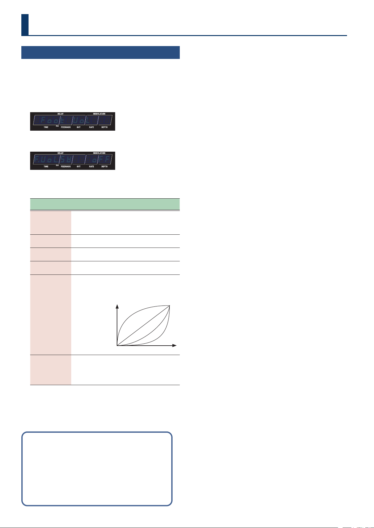
2. Use the [TIME] buttons to select “Foot$UoLFoot$UoL”.
¸¸¸¸¸¸¸¸¸¸¸¸$Foot$UoL
3. Press the [SETUP] button.
¸¸¸¸¸¸¸¸¸¸¸¸ƱUoŸSľ$$$off
4. Use the [TIME] buttons to select a parameter, and then
use the [DEPTH] buttons to change the value.
Parameter
[TIME] buttons
Value
[DEPTH] buttons
Explanation
ƱUoŸSľ
(Foot Vol Switch)
offoff
(o)
onon
(on)
Turns the foot volume on/o.
PEdAŸPoS
(Pedal Position)
00–100100
Sets the volume.
UoŸNin
(Volume Min)
00–100100
Sets the volume when the heel
of the EXP Pedal is depressed.
UoŸNAö
(Volume Max)
00–100100
Selects the volume when the toe
of the EXP Pedal is depressed.
CurUE
(Curve)
SLoľ1SLoľ1
(Slow1)
SLoľ2SLoľ2
(Slow2)
norNALnorNAL
(Normal)
FAStFASt
(Fast)
You can select how the actual
volume changes relative to the
amount the pedal is pressed.
Volume Min
Volume
Volume Max
Slow1
Slow2
Normal
Fast
FU.PrF
(Foot Vol Preference)
NENoryNENory
(Memory)
SYStENSYStEN
(System)
Sets whether the foot volume
should follow the settings for
the memories, or whether
it should follow the system
settings.
Preference parameters
“Preference parameters” are available on this unit.
Select “
NENory (Memory)” to congure the settings for each
memory.
Select “
SYStEN” (System) to follow the system settings, so that the
same settings are used even when switching to a dierent memory.
Change the setting as appropriate for your use case.
15
Selecting a Memory
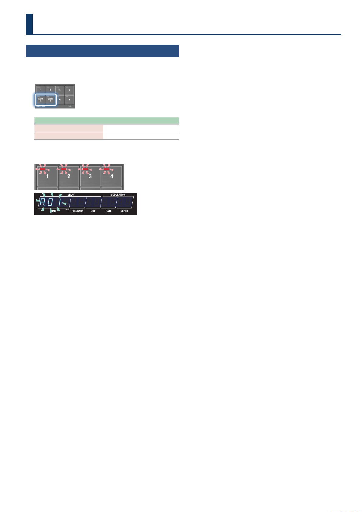
1. Press the [BANK A] button or the [BANK B] button to
select a bank.
Button (indicator color) Bank (memory)
[BANK A] button
BANK A (1–4)
[BANK B] button
BANK B (1–4)
When you select a bank, the indicators for the memory buttons and
the memory number in the display blink.
¸¸¸¸¸¸¸¸¸¸¸¸Ʒ01
2. Press the [1]–[4] buttons to select a memory.
Playing
16
Conguring the Delay Sound
(From the Top Panel)
Use the buttons to edit the parameters shown in the display.
1. Switch to the play screen parameter display (p. 4).
¸¸¸¸¸¸¸¸¸¸¸¸$4003130$0$0
2. Press the [DIGITAL DELAY 1] and [DIGITAL DELAY 2]
buttons to select the delay to operate.
3. Use the control buttons to congure the delay.
¸¸¸¸¸¸¸¸¸¸¸¸$4003130$0$0
Button
(parameter)
Value/Explanation
[TIME] buttons
Sets the delay time.
0.00.0–15001500
0.0–1500 ms (TIMEx2 o)
0.00.0–30003000
0.0–3000 ms (TIMEx2 on)
Note
Sets the time as a note value
(*1).
[FEEDBACK] buttons
00–qqqq
Sets the amount of feedback.
[OUT] buttons
00–qqqq
Sets the output volume of the
delay sound.
[RATE] buttons
00–qqqq,
oñoñ (note) *1
Sets the modulation speed.
[DEPTH] buttons
00–qqqq
Sets the modulation depth.
*1 Note values that can be set
Symbols Explanation
1_1b1_1b
Sixteenth note
8t8t
Eighth-note triplet
1bd1bd
Dotted sixteenth
note
1_81_8
Eighth note
4t4t
Quarter-note triplet
8d8d
Dotted eighth note
Symbols Explanation
1_41_4
Quarter note
2t2t
Half-note triplet
4d4d
Dotted quarter note
1_21_2
Half note
1t1t
Whole-note triplet
2d2d
Dotted half note
1_11_1
Whole note
* If the note value you’ve set exceeds the upper limit for the delay
time, the length is halved.
Other Delay Parameters
(DDL 1, DDL 2)
1. Press the [SETUP] button.
The parameter to set is shown in the display.
2. Use the [TIME] buttons to select “ddL1ddL1” “ddL2ddL2”, and
press the [SETUP] (ENTER) button.
3. Use the [TIME] buttons to select a parameter, and then
use the [DEPTH] buttons to change the value.
Parameter list
(common for DDL 1 and DDL 2)
MEMO
Use the [DIGITAL DELAY 1] button and [DIGITAL DELAY 2] button to
switch between the DDL 1 and DDL 2 parameters.
Parameter Value/Explanation
d±Sľ
(DDL 1 Switch)
d²Sľ
(DDL 2 Switch)
Turns DDL 1 or DDL 2 on/o.
oFFoFF
(O )
O
onon
(On)
On
d±tyP
(DDL 1 type)
d²tyP
(DDL 2 type)
Sets the type for DDL 1 or DDL 2.
StErEoStErEo
(Stereo)
A stereo-in/out delay.
PAnPAn
(Pan)
This gives a tap delay eect, with the
delay time (how long the sound is
delayed) divided into L and R channels.
d±tŷLinK
(DDL 1 Timelink)
d²tŷLinK
(DDL 2 Timelink)
Sets whether to independently control the DDL 1 or DDL
2 left-right delay time (o), or to use a common delay
time for the left and right (on).
oFFoFF
(O )
Sets the left-right delay time
independently.
onon
(On)
Sets a common left-right delay time.
oStoSt
(Oset)
Links the left and right channel delay
times while maintaining the oset. This
also follows the tap tempo.
d±oFFSt
(DDL 1 Oset)
d²oFFSt
(DDL 2 Oset)
When d±tŷLink, d²tŷLink is oSt, this
parameter is shown.
-qq-qq–00–qqqq
Sets how much to oset the delay time
of the R channel from the L channel
(in msec).
When the oset is “0”, the left and right
delays sound at the same time.
d±ľAUEFN
(DDL 1 Waveform)
d²ľAUEFN
(DDL 2 Waveform)
Selects the modulation waveform.
tritri
(Triangle)
Triangle wave
This is the original SDE-3000
waveform.
SinSin
(Sine)
Sine wave
d±Nod.PH
(DDL 1 Mod phase)
d²Nod.PH
(DD2. Mod phase)
Species the left-right phase.
nornor
(Normal)
Normal (in phase)
The phase does not change.
inUinU
(Invert)
Inverted (reverse phase)
The phase is inverted.
d±FƼEq.tP
(DDL 1 Feedback EQ type)
d²FƼEq.tP
(DDL 2 Feedback EQ type)
Selects the EQ type that’s applied to the delay feedback.
oFFoFF
(O )
The feedback EQ is o.
orGorG
(Original)
This is the original characteristic for the
SDE-3000.
vSrvSr
(User)
This can be freely congured in the
user settings.
Editing
17
Editing
Parameter Value/Explanation
d±Fb.LC.F
(
DDL 1 Feedback EQ Lo Freq
)
d²Fb.LC.F
(
DDL 2 Feedback EQ Lo Freq
)
*1
Cuts the frequency region below the specied frequency
(low-cut lter).
FLAtFLAt
(Flat)
The low-cut lter has no eect.
2020–800800
20, 25, 31.5, 40, 50, 63, 80, 100, 125,
160, 200, 250, 315, 400, 500, 630, 800
(Hz)
d±Fb.HC.F
(
DDL 1 Feedback EQ hi Freq
)
d²Fb.HC.F
(
DDL 2 Feedback EQ hi Freq
)
*1
Cuts the frequency region above the specied frequency
(high-cut lter).
ļ30ļ30–12.5k12.5k
630, 800, 1000, 1.25k, 1.6k, 2k, 2.5k,
3.15k, 4k, 5k, 6.3k, 8k, 10k, 12.5k (Hz)
FLAtFLAt
(Flat)
The high-cut lter has no eect.
d±Fb.HC.G
(
DDL 1 Feedback EQ Hc Gain
)
d²Fb.HC.G
(
DDL 2 Feedback EQ Hc Gain
)
*1
-24-24–00
Adjusts the tonal character of the high
frequencies.
*1 This is shown only when the
d±FƼEq.tP (DDL 1 Feedback EQ type) and
d²FƼEq.tP (DDL 2 Feedback EQ type) parameters are set to vSr (User).
Linking the Left and Right Delay Times
(Time Link)
Time Link is a function that lets you use the same delay times for the
left and right channels, or make them work independently.
1. Press the [SETUP] button.
The parameter to set is shown in the display.
2. Use the [TIME] buttons to select “ddL1ddL1” “ddL2ddL2”, and
press the [SETUP] (ENTER) button.
3. Use the [TIME] buttons to select the parameter, and
then use the [DEPTH] buttons to change the value.
Parameter Value/Explanation
d±tŷLink
(DDL 1 Timelink)
d²tŷLink
(DDL 2 Timelink)
Sets whether to independently control the DDL 1 or
DDL 2 left-right delay time (o), or to use a common
delay time for the left and right (on).
oFFoFF
(O )
Sets the left-right delay time
independently.
onon
(On)
Sets a common left-right delay
time.
oStoSt
(Oset)
Links the left and right channel
delay times while maintaining the
oset. This also follows the tap
tempo.
d±oFFSt
(DDL 1 Oset)
d²oFFSt
(DDL 2 Oset)
When d±tŷLink, d²tŷLink is oSt, this
parameter is shown.
-qq-qq–00–qqqq
Sets how much to oset the delay
time of the R channel from the L
channel (in msec).
When the oset is “0”, the left and
right delays sound at the same
time.
Setting the Left and Right Channels to the Same
Delay Time
(Time Link: ON)
When you set the oset to “0” while Time Link is ON, the left and
right channels use the same delay times. When you use tap tempo to
change the delay time, the left and right channel delays still stay the
same.
1. Press the [SETUP] button.
2. Use the [TIME] buttons to select “ddL1ddL1” “ddL2ddL2”, and
press the [SETUP] (ENTER) button.
3. Use the [TIME] buttons to select “d±tŷLinkd±tŷLink”
“d²tŷLinkd²tŷLink”, and then use the [DEPTH] buttons to
change the value to “onon”.
Setting the Left and Right Delay Times
Independently
(Time Link: OFF)
When Time Link is OFF, the left and right channel delay times can be
set independently. When you use tap tempo to change the delay time,
only the delay for the selected channel (left or right) is changed.
1. Press the [SETUP] button.
2. Use the [TIME] buttons to select “ddL1ddL1” “ddL2ddL2”, and
press the [SETUP] (ENTER) button.
3. Use the [TIME] buttons to select “d±tŷLinkd±tŷLink”
“d²tŷLinkd²tŷLink”, and then use the [DEPTH] buttons to
change the value to “oFFoFF”.
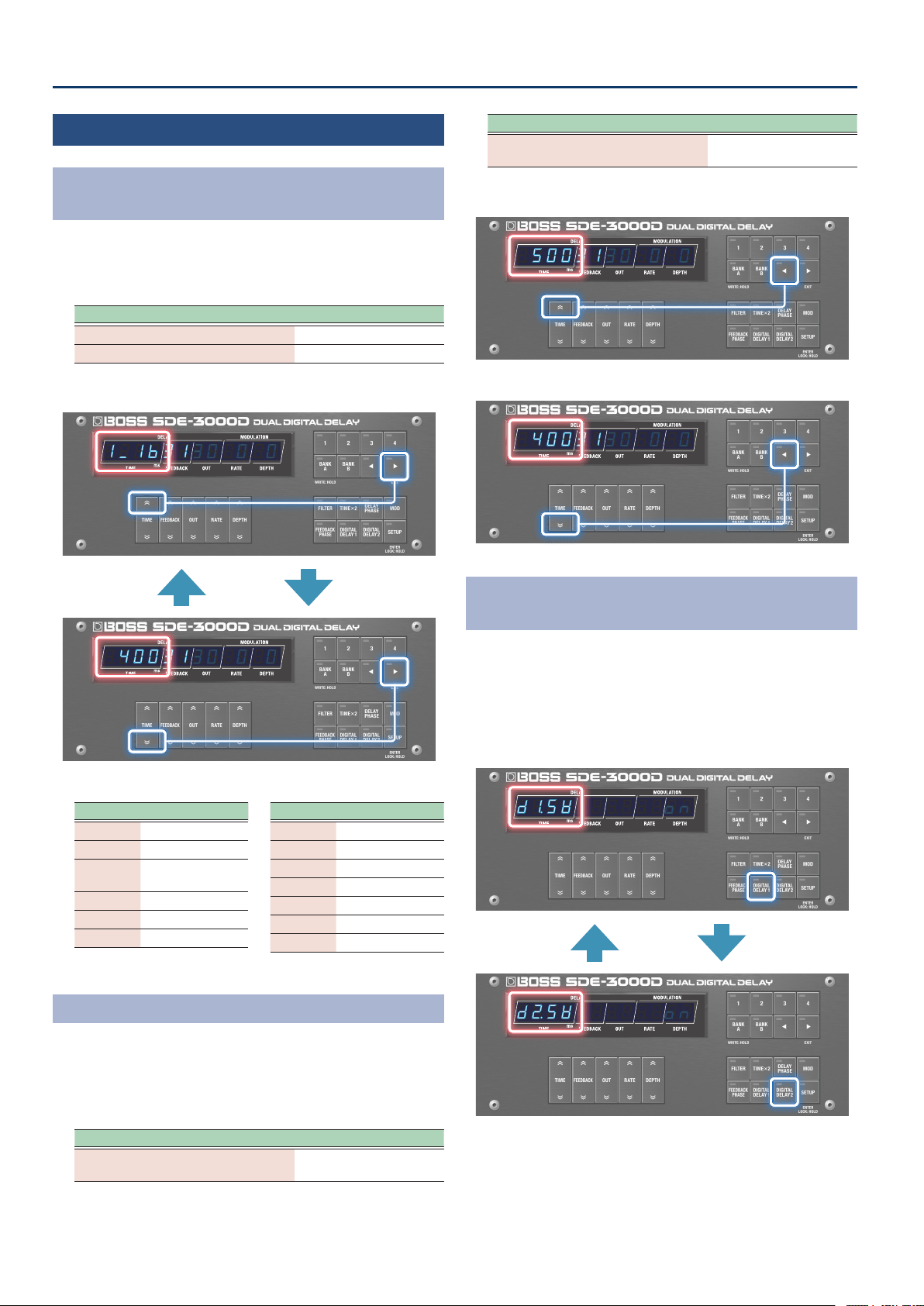
Outputting a delay with dierent times
(Lch: 400 msec; Rch: 800 msec)
DDL 1 (L/R)
Lch
Rch
1. Press the [DIGITAL DELAY 1] button to make it light up
green, and set the “TIME” to “400”.
2. Press the [DIGITAL DELAY 1] button to make it light up
red, and set the “TIME” to “800”.
Setting the Left and Right Channels to Dierent
Delay Times
(Time Link: OFFSET)
You can adjust the delay time oset to set dierent delay times for the
left and right channels. When you use tap tempo to change the delay
time, the oset still stays the same.
1. Press the [SETUP] button.
2. Use the [TIME] buttons to select “ddL1ddL1” “ddL2ddL2”, and
press the [SETUP] (ENTER) button.
3. Use the [TIME] buttons to select “d±tŷLinkd±tŷLink”
“d²tŷLinkd²tŷLink”, and then use the [DEPTH] buttons to
change the value to “oStoSt”.
18
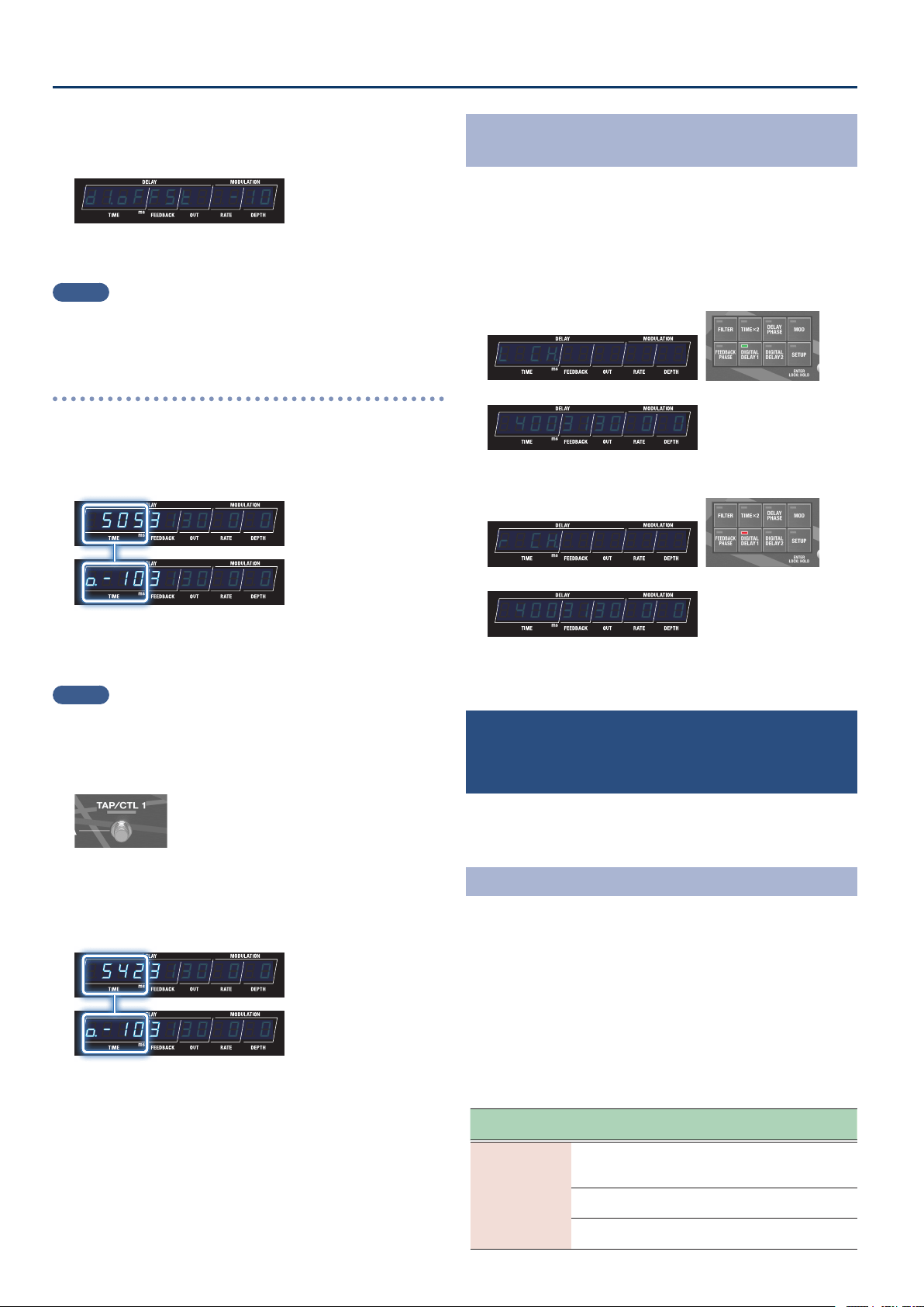
Editing
4. Use the [TIME] buttons to select “d±oFFStd±oFFSt” or
“d²oFFStd²oFFSt”, and then use the [DEPTH] buttons to
change the value.
¸¸¸¸¸¸¸¸¸¸¸¸d±oFFSt$$-10
The R channel value is oset from the L channel by the amount set
(-10 msec).
MEMO
When the oset is “0”, the left and right delays sound at the same
time.
When the delay time is set to “505 msec” and the oset
is set to “-10”
You can oset the delay times by a tiny amount to create an expansive,
spatially synthesized delay sound.
¸¸¸¸¸¸¸¸¸¸¸¸$5053130$0$0
¸¸¸¸¸¸¸¸¸¸¸¸Ɯ-103130$0$0
L channel
(505 msec)
From this screen, you can press the [TIME] buttons to edit the delay time.
R channel
(495 msec)
The oset value that you set (which starts with “Ɯ”) is shown.
From this screen, you can press the [TIME] buttons to edit the oset value.
MEMO
When you keep pressing the [DIGITAL DELAY 1] or [DIGITAL DELAY
2] button, the setting switches between the L and R channels each
time you press the buttons.
1. Change the delay time using tap tempo.
The oset always remains the same even if the tempo changes,
which lets you keep the same stereo image.
¸¸¸¸¸¸¸¸¸¸¸¸$5423130$0$0
¸¸¸¸¸¸¸¸¸¸¸¸Ɯ-103130$0$0
L channel
(542 msec)
From this screen, you can press the [TIME] buttons to edit the delay time.
R channel
(532 msec)
The oset value that you set (which starts with “Ɯ”) is shown.
From this screen, you can press the [TIME] buttons to edit the oset value.
Switching Between Left and Right Time Display for
DDL 1/DDL 2
1. Press the [DIGITAL DELAY 1] or [DIGITAL DELAY 2]
button, corresponding to which indicator is lit.
Each time you press the button, the display switches between the
left and right times, and the channel you select (Lch/Rch) appears
as a pop-up in the display.
L channel
(indicator lights up green)
¸¸¸¸¸¸¸¸¸¸¸¸L$Cƶ
¸¸¸¸¸¸¸¸¸¸¸¸$4003130$0$0
R channel
(indicator lights up red)
¸¸¸¸¸¸¸¸¸¸¸¸r$Cƶ
¸¸¸¸¸¸¸¸¸¸¸¸$4003130$0$0
Parameters aside from delay time are the same for both left and
right.
Carrying Over Reverberations when Switching
the Delays On/O or When Switching Between
Memories
(Carryover)
When the carryover function is on, you can make the reverberations
of the previous delay continue to sound even when you switch the
delays on/o or switch between memories.
Turning On the Carryover
1. Press the [SETUP] button.
2. Use the [TIME] buttons to select “NASTERNASTER”, and press
the [SETUP] (ENTER) button.
3. Use the [TIME] buttons to select “d±CrYoUrd±CrYoUr” or
“d²CrYoUrd²CrYoUr”, and then use the [DEPTH] buttons to
change the value to “onon”.
Carryover parameter
(in MASTER settings)
Parameter
[TIME] buttons
Value
[DEPTH] buttons
Explanation
d±CrYoUr
(DDL 1 Caryover)
d²CrYoUr
(DDL 2 Caryover)
When this is on, you can make the reverberations of the
previous delay continue to sound even when you switch
the delays on/o or switch between memories.
oFFoFF
(O )
Disables the carryover.
onon
(On)
Enables the carryover.
19
Editing
Setting the Tempo
(BPM)
Here’s how to set the tempo when the delay time was set using a note
length.
1. Press the [SETUP] button.
2. Use the [TIME] buttons to select “NASTERNASTER”, and press
the [SETUP] (ENTER) button.
3. Use the [TIME] buttons to select “BPNBPN”, and then use
the [DEPTH] buttons to change the value.
BPM parameter
(in MASTER settings)
Parameter
[TIME] buttons
Value
[DEPTH] buttons
Explanation
BPN
(BPM)
4040–250250
Species the tempo.
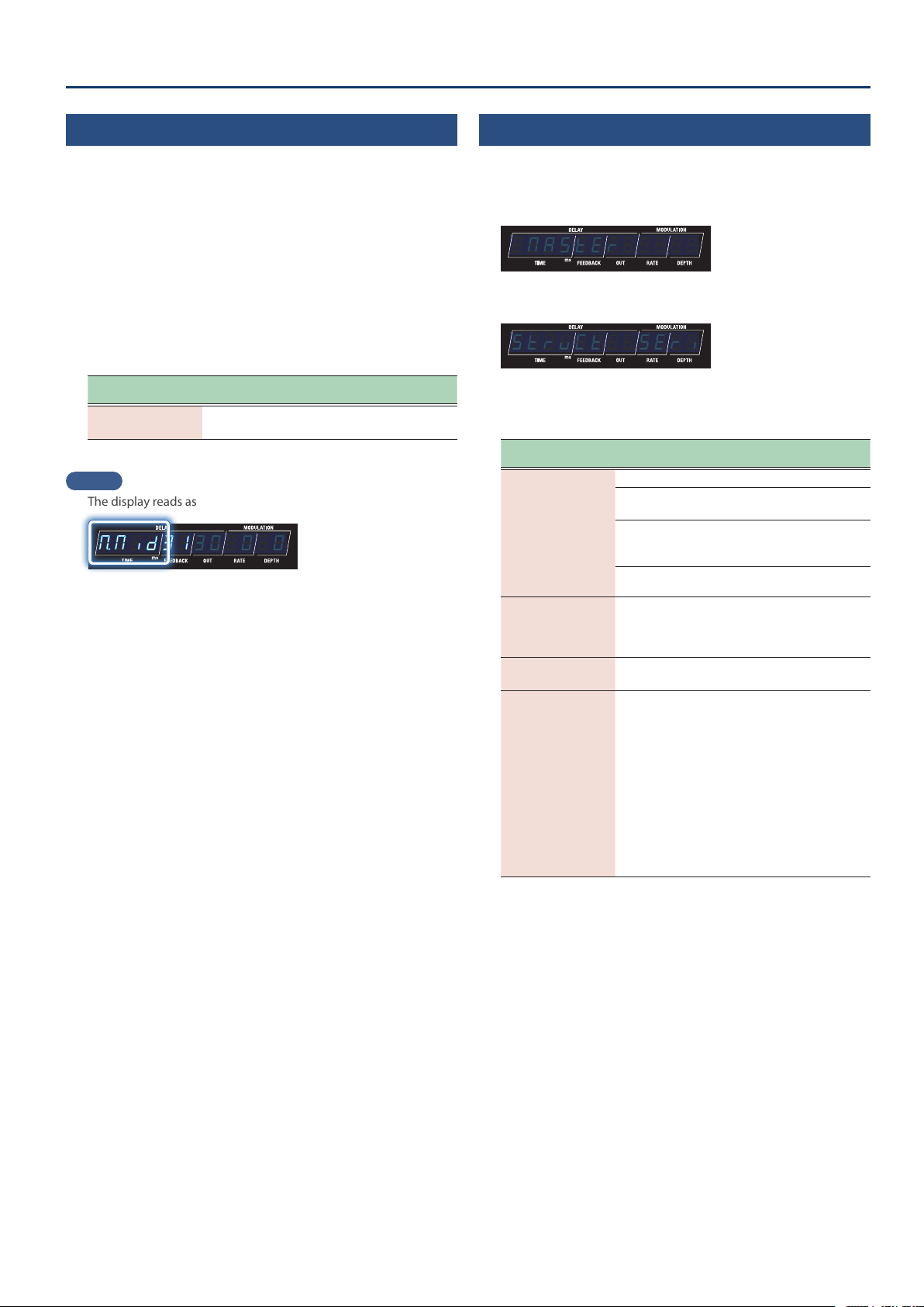
MEMO
The display reads as follows when an external clock is received.
¸¸¸¸¸¸¸¸¸¸¸¸ŷNid3130$0$0
Setting the Other Parameters
(MASTER)
1. Press the [SETUP] button.
2. Use the [TIME] buttons to select “NASTERNASTER”.
¸¸¸¸¸¸¸¸¸¸¸¸$NASTER
3. Press the [SETUP] (ENTER) button.
¸¸¸¸¸¸¸¸¸¸¸¸StrvCt$$SEri
4. Use the [TIME] buttons to select a parameter, and then
use the [DEPTH] buttons to change the value.
Parameter
[TIME] buttons
Value
[DEPTH] buttons
Explanation
NoƞLink
(Mod Link)
This is shown when the structure is “Parallel 2”.
nornor
(Normal)
Aligns the phase of modulation
between DDL 1 and DDL 2.
inuinu
(Invert)
Reverses the phase of
modulation between DDL 1 and
DDL 2.
offoff
(o)
Sets this to o (free running).
diƐLEUEL
(Direct Level)
00–100100
Sets the direct level.
When this is set to “60”, the
input/output balance is 1:1
(unity gain).
ovƸGAin
(Output Gain)
-12-12–1212
Adjusts the output level.
tENpƜHLD
(Tempo Hold)
offoff
(o)
onon
(on)
Species whether the tempo
(BPM) is changed (oFF) or
held (on) or when you switch
memories.
You can keep the same delay
time by maintaining the tempo.
However, note that when the
NOTE setting (note value) of
the patch you’re switching to
is dierent, the delay time also
changes.
The setting can be changed for
each memory.
20
Editing
Useful Functions
Switching Between Note Length and Time Display
for the Delay Time
1. When the play screen is showing the parameter, hold
down the [â] button and press the [TIME] buttons up
and down.
Operation Display
[â] button + [TIME (up)] button
Note length display
[â] button + [TIME (down)] button
Time display
¸¸¸¸¸¸¸¸¸¸¸¸
$4003130$0$0
Time display
¸¸¸¸¸¸¸¸¸¸¸¸
1_1b3130$0$0
Note length display
Note values that can be set
Symbols Explanation
1_1b1_1b
Sixteenth note
8t8t
Eighth-note triplet
1bd1bd
Dotted sixteenth
note
1_81_8
Eighth note
4t4t
Quarter-note triplet
8d8d
Dotted eighth note
Symbols Explanation
1_41_4
Quarter note
2t2t
Half-note triplet
4d4d
Dotted quarter note
1_21_2
Half note
1t1t
Whole-note triplet
2d2d
Dotted half note
1_11_1
Whole note
Make Large Changes to the Delay Time
1. When the delay time on the play screen is displayed as
time, hold down the [ã] button and press the [TIME]
button up or down.
The set value increases or decreases signicantly.
Operation Display
[ã] button + [TIME (up)] button
The set value increases
signicantly.
Operation Display
[ã] button + [TIME (down)] button
The set value decreases
signicantly.
¸¸¸¸¸¸¸¸¸¸¸¸
$5003130$0$0
Increase the setting value signicantly
¸¸¸¸¸¸¸¸¸¸¸¸
$4003130$0$0
Decrease setting value signicantly
Switching Between DDL 1 and DDL 2 on the
Parameter Setting Screen
1. Press the [DIGITAL DELAY 1] and [DIGITAL DELAY 2]
buttons when editing the delay.
The display switches to the settings screen for the delay you
selected by pressing the buttons without changing any parameters.
The indicator for the selected delay lights up.
¸¸¸¸¸¸¸¸¸¸¸¸
d²sľ$$$$$$on
DDL 2
¸¸¸¸¸¸¸¸¸¸¸¸
d±sľ$$$$$$on
DDL 1
21
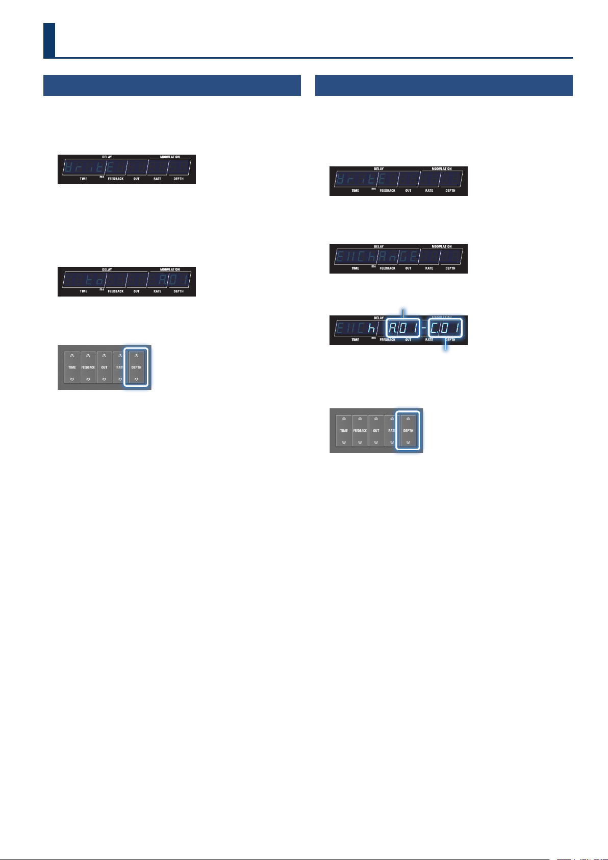
Saving to Memory
(WRITE)
Here’s how to save the currently selected memory.
1. Long-press the [BANK A] (WRITE) button.
The write menu appears.
¸¸¸¸¸¸¸¸¸¸¸¸ľritE
If “ľritE” is not shown on the display, press the [TIME] buttons to
select “ľritE”.
2. Press the [SETUP] (ENTER) button.
The memory number of the write destination is shown.
¸¸¸¸¸¸¸¸¸¸¸¸$$to$$$$$Ʒ01
3. To change the write destination, select the memory
number with the [DEPTH] buttons.
Press the [â] (EXIT) button if you want to cancel and return to the
write menu.
4. To save the memory, press the [BANK A] (WRITE)
button.
When the memory is nished saving, the unit switches to the write
destination memory and returns to the play screen.
Swapping Memories
(EXCHANGE)
Here’s how to swap (exchange) the memory number of the saved
memory with a dierent one.
1. Long-press the [BANK A] (WRITE) button.
The write menu appears.
¸¸¸¸¸¸¸¸¸¸¸¸ľritE
2. Use the [TIME] buttons to select “EöChAnGEEöChAnGE”, and
press the [SETUP] (ENTER) button.
¸¸¸¸¸¸¸¸¸¸¸¸EöChAnGE
The memory number to exchange is shown.
¸¸¸¸¸¸¸¸¸¸¸¸EöCh$Ʒ01-Ź01
Memory number to exchange
Selected memory number
3. To change the number of the memory to exchange, use
the [DEPTH] buttons to select the memory number.
Press the [â] (EXIT) button if you want to cancel and return to the
write menu.
4. To exchange, press the [BANK A] (WRITE) button.
The unit returns to the play screen when the exchange operation is
nished.
Saving, Exchanging and Other Memory Operations
22
Saving, Exchanging and Other Memory Operations
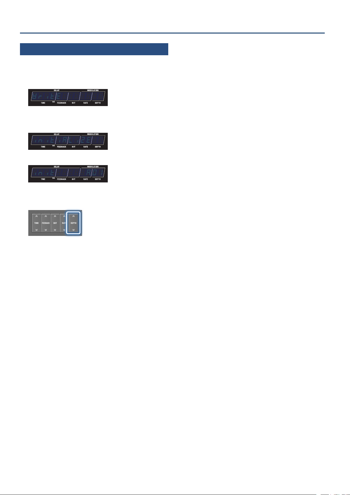
Initializing a Memory
(INITIALIZE)
Here’s how to initialize the selected memory.
1. Long-press the [BANK A] (WRITE) button.
The write menu appears.
¸¸¸¸¸¸¸¸¸¸¸¸ľritE
2. Use the [TIME] buttons to select “initiALiZEinitiALiZE”, and
press the [SETUP] (ENTER) button.
¸¸¸¸¸¸¸¸¸¸¸¸initiALiZE
The memory number to initialize is shown.
¸¸¸¸¸¸¸¸¸¸¸¸init$$$$$Ʒ01
3. To change the number of the memory to initialize, use
the [DEPTH] buttons to select the memory number.
Press the [â] (EXIT) button if you want to cancel and return to the
write menu.
4. To initialize, press the [BANK A] (WRITE) button.
The unit returns to the play screen when the initialize operation is
nished.
23
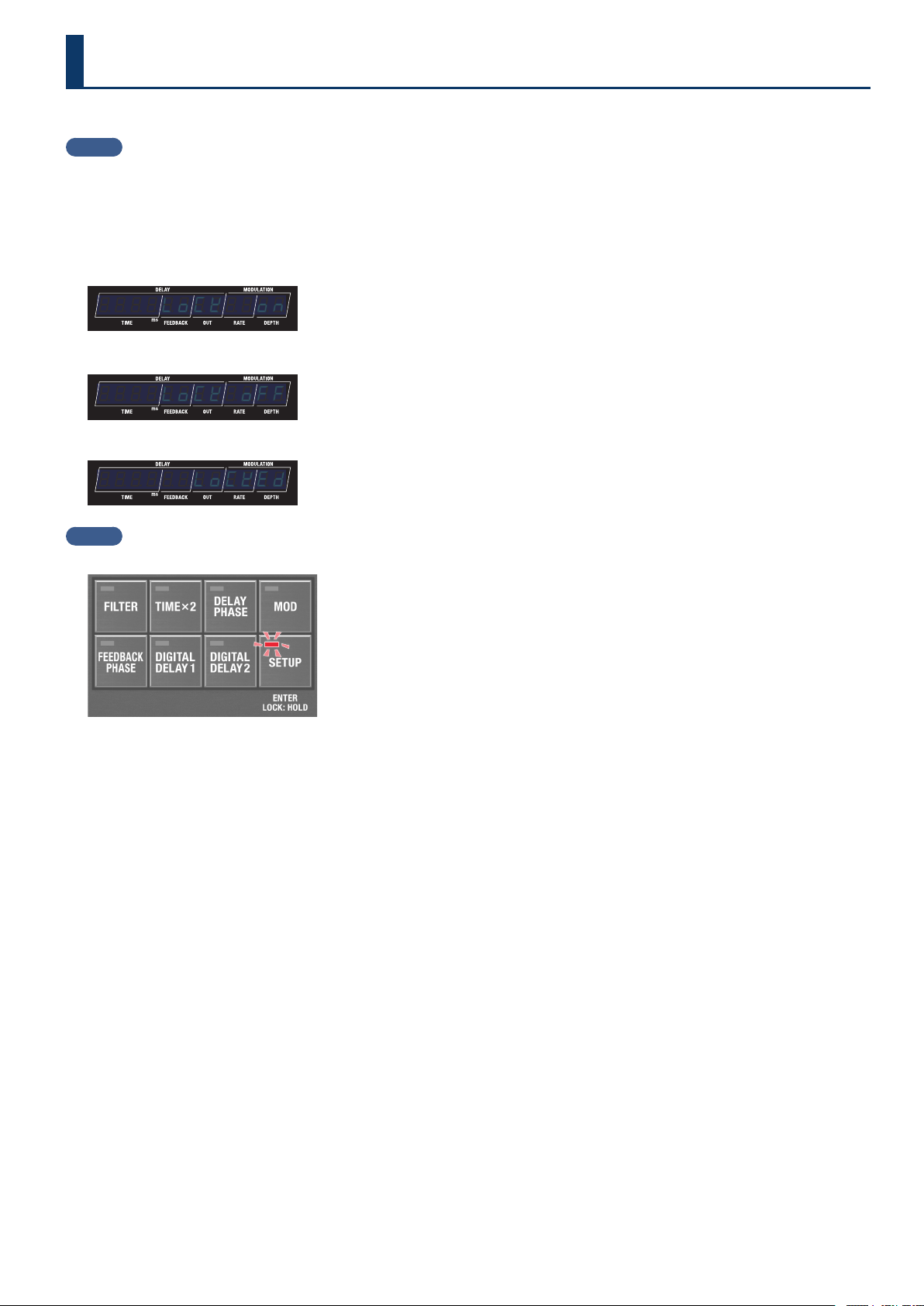
You can enable (Lock OFF) or disable (Lock ON) the button operations.
MEMO
The panel lock setting is disabled when the power is turned o.
1. Long-press the [SETUP] button to return to the play screen.
The setting toggles between on and o each time you press the button.
The screens change as shown below when the status changes, and the unit returns to the play screen.
Lock ON
¸¸¸¸¸¸¸¸¸¸¸¸$$$$LoCk$$on
Lock OFF
¸¸¸¸¸¸¸¸¸¸¸¸$$$$LoCk$oFF
If you attempt an operation while the unit is locked, the display indicates “LoCKED”.
¸¸¸¸¸¸¸¸¸¸¸¸$$$$$$LoCkEd
MEMO
When the panel lock is on, the [SETUP] button lights up.
Preventing Accidental Operation (Panel Lock)
24
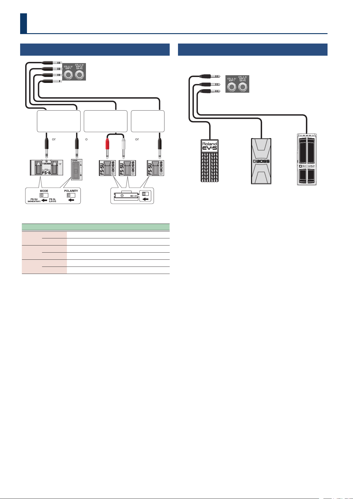
Connecting Footswitches
FS-5U
or
FS-6
Rear panel
FS-7
Stereo 1/4” phone type
Ð
1/4” phone type × 2
FS-5U
or or
1/4” phone type
Ð
1/4” phone type
The polarity switch is set as shown
in the illustration.
Ring Tip
Stereo 1/4” phone type
Ð
Stereo 1/4” phone type
Footswitch CTL 2, 3/EXP 1 jack CTL4, 5/EXP2/GA-FC jack
FS-6
A
CTL 3 CTL 5
B
CTL 2 CTL 4
FS-7
A
CTL 3 CTL 5
B
CTL 2 CTL 4
FS-5U
RING (red)
CTL 2 CTL 4
TIP
CTL 3 CTL 5
* This unit is compatible with latch-type footswitches.
If you’re using an FS-6 or FS-7, set the mode of A and B to FS-5U
(MOMENTARY).
Supported footswitches
Sold separately: FS-5U, FS-5L, FS-6, FS-7
Connecting an Expression Pedal
You can connect an expression pedal for controlling the volume and
other parameters.
Rear panel
EV-30 FV-500H
FV-500L
Roland
EV-5
* Use only the specied expression pedal. Connecting any other
expression pedals may cause malfunctions and/or damage to this
unit.
Supported expression pedals
Sold separately: BOSS EV-30, FV-500L, FV-500H, Roland EV-5
Conguring the External Controllers
25
Conguring the External Controllers
Conguring the CTL Function
(CTL)
1. Press the [SETUP] button.
The parameter to set is shown in the display.
2. Use the [TIME] buttons to select “CtLCtL”, and press the
[SETUP] (ENTER) button.
¸¸¸¸¸¸¸¸¸¸¸¸$CtL
3. Use the [TIME] buttons to select a parameter, and then
use the [DEPTH] buttons to change the value.
Control parameters
Parameter
[TIME] buttons
Value
[DEPTH] buttons
Explanation
C1.FnC
(CTL 1 Function)
C5.FnC
(CTL 5 Function)
oFFoFF
(O )
Turns the CTL 1–CTL 5 switches OFF.
bPŷtApbPŷtAp
(BPM Tap)
Tap to input the BPM.
d±²tAPd±²tAP
(DDL 1/DDL 2 Tap)
DDL 1 and
DDL 2 (at the
same time)
Tap to input the
delay time.
d±ŸtAPd±ŸtAP
(DDL 1 Lch Tap)
L channel of
DDL 1
d±ƐtAPd±ƐtAP
(DDL 1 Rch Tap)
R channel of
DDL 1
d²ŸtAPd²ŸtAP
(DDL 2 Lch Tap)
L channel of
DDL 2
d²ƐtAPd²ƐtAP
(DDL 2 Rch Tap)
R channel of
DDL 2
d±²Sľd±²Sľ
(DDL 1/DDL 2 Switch)
DDL 1 and
DDL 2 (at the
same time)
Turns the eect(s)
on/o.
d±Sľd±Sľ
(DDL 1 Switch)
DDL 1
d²Sľd²Sľ
(DDL 2 Switch)
DDL 2
d±²HLdd±²HLd
(DDL 1/DDL 2 Hold)
DDL 1 and
DDL 2 (at the
same time)
The delay sound
repeats for as long
as you press the
switch (*1, *2).
d±HoLdd±HoLd
(DDL 1 Hold)
DDL 1
d²HoLdd²HoLd
(DDL 2 Hold)
DDL 2
d±²NoNd±²NoN
(DDL 1/DDL 2 MOMENT)
DDL 1 and
DDL 2 (at the
same time)
The delay sound is
output for as long as
you press the switch
(*1).
d±NoNd±NoN
(DDL 1 MOMENT)
DDL 1
d²NoNd²NoN
(DDL 2 MOMENT)
DDL 2
bYPASSbYPASS
(Bypass)
Turns the bypass on/o.
When this is on, the audio input is
outputted as-is.
Ø “Bypass circuit diagram (using
an external controller to activate
bypass)” (p. 30)
NEŷvPNEŷvP
(Memory up)
Switches to the next memory.
NEŷdnNEŷdn
(Memory down)
Switches to the previous memory.
NEŷnvNNEŷnvN
(MEMORY NUMBER)
Lets you assign a desired memory
number for quick recall (this
function is not available in C1.FnC).
Parameter
[TIME] buttons
Value
[DEPTH] buttons
Explanation
C²nvN
(CTL 2 Number)
CµnvN
(CTL 5 Number)
Ʒ01Ʒ01–0404,
Ƽ01Ƽ01–0404,
Ź01Ź01–q2q2
When you set NEŷnvN (MEMORY
NUMBER) for C2.FnC (CTL
2 Function)–C5.FnC (CTL 5
Function), this can be assigned to
the memories for each controller.
C±d±HoLD
(CTL1 DDL 1 Hold)
Cµd²HoLD
(CTL5 DDL 2 Hold)
When C1.FnC–C5.FnC is d±²HLd, d±HoLd,
d²HoLd
00–120120
Adjusts the Hold level.
C1.Nod
(CTL1.Mode)
C5.Nod
(CTL5.Mode)
When C±FnC–CµFnC are oFF, tAP or NEŷvP
NEŷdn,
this parameter is not shown.
toGGLEtoGGLE
(Toggle)
Toggles between on and o each
time you operate the control.
NoNEntNoNEnt
(Moment)
Turns on only while you are pressing
down on the switch, and turns o
otherwise.
C±Prf
(CTL1 PREFERENCE)
CµPrf
(CTL5 PREFERENCE)
NENoryNENory
(Memory)
Sets whether to use to dierent
settings per memory for the CTL
switches (NENory), or to use
the same settings for all memories
(SYStEN).
SYStENSYStEN
(System)
E±.FnC
(EXP1.Function)
E²FnC
(EXP2.Functioon)
oFFoFF
(O )
The EXP 1 and EXP 2 are not used.
FUFU
(Foot Volume)
Adjusts the volume for the foot
volume control.
d±tiŷLd±tiŷL
(DDL 1 Time Lch)
L channel of
DDL 1
Adjusts the delay
time.
* The note length is not
shown.
d±tiŷrd±tiŷr
(DD1 Time Rch)
R channel of
DDL 1
d²tiŷLd²tiŷL
(DDL 2 Time Lch)
L channel of
DDL 2
d²tiŷrd²tiŷr
(DD2 Time Rch)
R channel of
DDL 2
d±FbKd±FbK
(DDL 1 Feedback)
DDL 1
Adjusts the amount
of feedback.
d²FbKd²FbK
(DDL 2 Feedback)
DDL 2
d±ovtd±ovt
(DDL 1 Out)
DDL 1
Adjusts the delay
volume.
d²ovtd²ovt
(DDL 2 Out)
DDL 2
d±ŷrAtd±ŷrAt
(DDL 1 Modulation Rate)
DDL 1
Adjusts the
modulation rate.
d²ŷrAtd²ŷrAt
(DDL 2 Modulation Rate)
DDL 2
d±ŷdPtd±ŷdPt
(DDL 1 Modulation Depth)
DDL 1
Adjusts the
modulation depth.
d²ŷdPtd²ŷdPt
(DDL 2 Modulation Depth)
DDL 2
diƐLULdiƐLUL
(Direct Level)
Adjusts the direct level.
E±Nin
(EXP1.Min)
E²Nin
(EXP2.Min)
The variable range
diers depending
on the parameter.
Sets the minimum value for
the parameter controlled by an
expression pedal.
E±NAö
(EXP1.Max)
E²NAö
(EXP2.Max)
The variable range
diers depending
on the parameter.
Sets the maximum value for
the parameter controlled by an
expression pedal.
E±PrF
(EXP1 PREFERENCE)
E²PrF
(EXP2 PREFERENCE)
NENoryNENory
(Memory)
Sets whether to use dierent
settings per memory for the EXP
pedals (NENory), or to use the
same settings for all memories
(SYStEN).
SYStENSYStEN
(System)
*1 The relevant C1.NodEC1.NodE (CTL1.Mode)–C5.NodEC5.NodE (CTL5.Mode) parameters
must be set to NoNEntNoNEnt (Moment).
*2 Use caution, as the output volume may increase when you switch the delay
on/o while holding or apply modulation.
26
Conguring the External Controllers
Assign Settings
(ASSIGN)
You can assign the functions you prefer to the [CTL 1] switch and to the
footswitches you’ve connected.
Up to eight assign settings can be saved for each memory.
1. Press the [SETUP] button.
The parameter to set is shown in the display.
2. Use the [TIME] buttons to select “ASSiGnASSiGn”, and press
the [SETUP] (ENTER) button.
¸¸¸¸¸¸¸¸¸¸¸¸$ASSiGn
¸¸¸¸¸¸¸¸¸¸¸¸A±Sľ$$$$$off
3. Use the [TIME] buttons to select the switch assignment
“A±SľA±Sľ”
(Assign 1 Switch)
–”A¸SľA¸Sľ”
(Assign 8 Switch)
, and use the
[DEPTH] buttons to set this to “onon”.
MEMO
All assignments are turned o by default, and the setting parameters
are not shown. To set an assignment, rst turn on the assignment’s
switch.
4. Use the [TIME] buttons to select a parameter, and then
use the [DEPTH] buttons to change the value.
Assign parameters
Parameter
[TIME] buttons
Value
[DEPTH] buttons
Explanation
A±Sľ
(Assign 1 Switch)
A¸Sľ
(Assign 8 Switch)
offoff
(o)
onon
(on)
Turns Assign 1–8 on/o.
When this is turned on, you can set
the following parameters.
A±SrC
(Assign 1 Source)
A¸SrC
(Assign 8 Source)
CtL1CtL1––CTL5CTL5
(CTL 1–CTL 5)
CTL 1–CTL 5
switches
Select the
controller
used for the
assignment.
EöP1EöP1
(EXP1)
EöP2EöP2
(EXP2)
EXP1, EXP2
pedal
GAFŹ1GAFŹ1––GAFŹ4GAFŹ4
(GA-FC [CH1]–[CH4])
GAFŹPGAFŹP
(GA-FC [Panel])
GAFŹEGAFŹE
(GA-FC [Eects])
GA-FC [CH1]–[CH4]
switch, GA-FC
[Pedal] switch, GA-
FC [Eect] switch
GAFŹE1GAFŹE1
(GA-FC EXP1)
GAFŹE2GAFŹE2
(GA-FC EXP2)
GA-FC EXP1,
EXP2 pedal (*1)
GAFŹS1GAFŹS1
(GA-FC S1)
GAFŹS2GAFŹS2
(GA-FC S2)
GA-FC S1, S2
(*1)
cc01cc01––cc31cc31
(CC01–CC31)
ccb4ccb4––ccq5ccq5
(CC64–CC95)
CC01–31,
CC64–95
A±Nod
(Assign 1 Mode)
A¸Nod
(Assign 8 Mode)
toGGLEtoGGLE
(Toggle)
The setting is toggled OFF
(minimum value) or ON (maximum
value) with each operation.
NoNEntNoNEnt
(Moment)
The normal state is OFF (minimum
value), and is ON (maximum
value) only while the controller is
operated.
*1 Pedal jack of the GA-FC
GA-FC
GA-FC EX
GAFŹE1GAFŹE1
(GA-FC EXP1)
GAFŹS1GAFŹS1
(GA-FC S1)
GAFŹE2GAFŹE2
(GA-FC EXP2)
GAFŹS2GAFŹS2
(GA-FC S2)
Sets the functions of the EXP pedal.
Sets the functions of the footswitch.
27
Conguring the External Controllers
Parameter
[TIME] buttons
Value
[DEPTH] buttons
Explanation
A±trG
(Assign 1 Target)
A¸trG
(Assign 8 Target)
This selects the function assigned to the controller.
Set the minimum/maximum values for each selected
function as a Min/Max value. Toggle between the “Nin”
and “NAö” parameters according to the mode for each
assignment.
d±Sľd±Sľ
(DDL 1 Switch)
DDL 1
Turns the delay
on/o.
d²Sľd²Sľ
(DDL 2 Switch)
DDL 2
d±TiŷLd±TiŷL
(DDL 1 Time Lch)
L channel of
DDL 1
Adjusts the delay
time.
d±Tiŷrd±Tiŷr
(DDL 1 Time Rch)
R channel of
DDL 1
d²TiŷLd²TiŷL
(DDL 2 Time Lch)
L channel of
DDL 2
d²Tiŷrd²Tiŷr
(DDL 2 Time Rch)
R channel of
DDL 2
d±FBKd±FBK
(DDL 1 Feedback)
DDL 1
Adjusts the
amount of
feedback.
d²FBKd²FBK
(DDL 2 Feedback)
DDL 2
d±ovtd±ovt
(DDL 1 Output)
DDL 1
Adjusts the
output volume of
the delay sound.
d²ovtd²ovt
(DDL 2 Output)
DDL 2
d±rAtEd±rAtE
(DDL 1 Rate)
DDL 1
Adjusts the delay
rate.
d²rAtEd²rAtE
(DDL 2 Rate)
DDL 2
d±dEPtd±dEPt
(DDL 1 Depth)
DDL 1
Adjusts the delay
dept.
d²dEPtd²dEPt
(DDL 2 Depth)
DDL 2
d±Nodd±Nod
(DDL 1 Modulation)
DDL 1
Turns the
modulation on/
o.
* Works the same as
the [MOD] button
on the top panel.
d²Nodd²Nod
(DDL 2 Modulation)
DDL 2
d±FƼPHd±FƼPH
(DDL 1
Feedback Phase
)
DDL 1
Switches the
FEEDBACK PHASE
on/o.
* Works the same
as the [FEEDBACK
PHASE] button on
the top panel.
d²FƼPHd²FƼPH
(DDL 2
Feedback Phase
)
DDL 2
DiƐLEUDiƐLEU
(Direct Level)
Adjusts the direct level.
ƱUoŸSľƱUoŸSľ
(Foot Volume Switch)
Turns the foot volume on/o.
PdŸPosPdŸPos
(Pedal Position)
Pedal position
A±Nin
(Assign 1 Min)
A¸Nin
(Assign 8 Min)
The variable range
diers depending
on the parameter.
This sets the minimum value for the
range in which the parameter can
change.
A±NAö
(Assign 1 Max)
A¸NAö
(Assign 8 Max)
The variable range
diers depending
on the parameter.
This sets the maximum value for the
range in which the parameter can
change.
Parameter
[TIME] buttons
Value
[DEPTH] buttons
Explanation
A±ACL
(Assign 1 ACT Low)
A¸ACL
(Assign 8 ACT Low)
00–12ļ12ļ
You can set the controllable range
for target parameters within the
source’s operational range.
Target parameters are controlled
within the range set with ACT LOW
and ACT HIGH.
You should normally set ACT LOW
to 0 and ACT HIGH to 127.
A±ACH
(Assign 1 ACT High)
A¸ACH
(Assign 8 ACT High)
11–127127
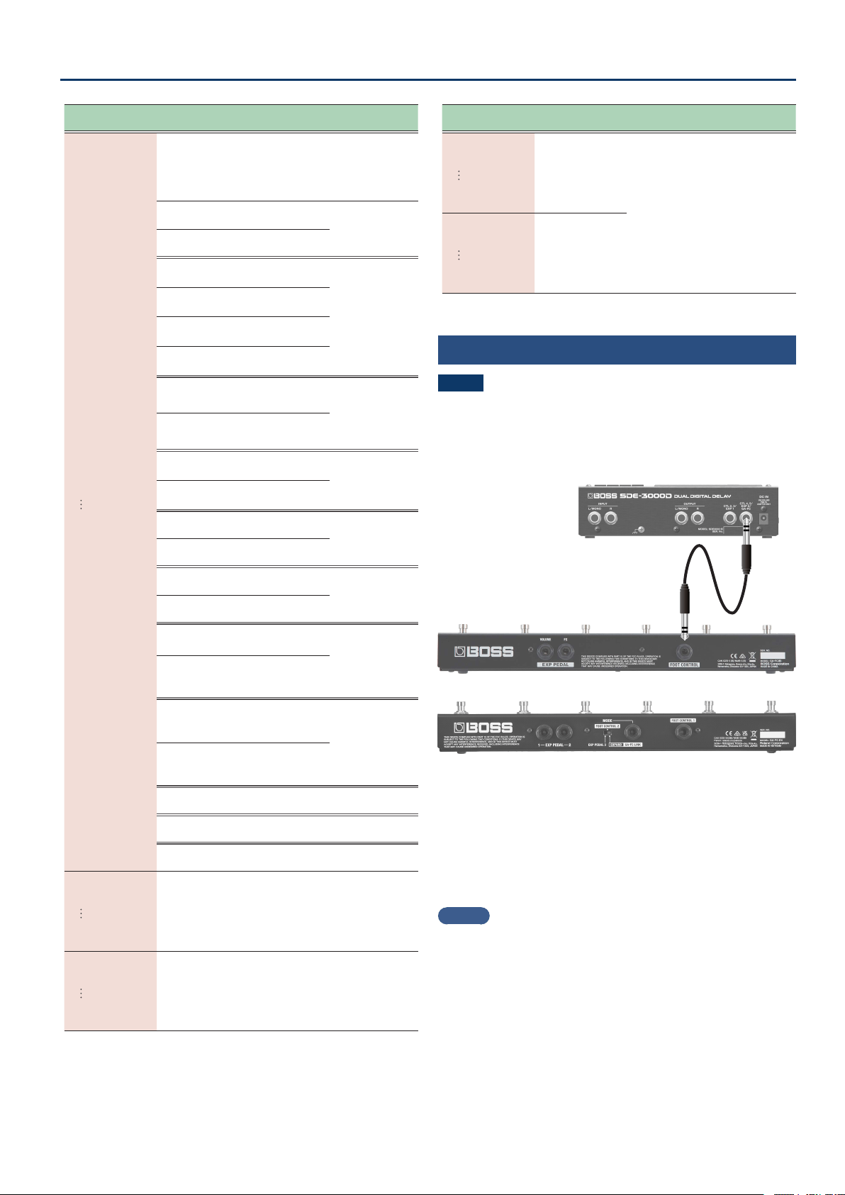
Connecting the GA-FC
NOTE
¹ If you’re using a GA-FC, turn the GAFC switch ON before
connecting. The unit may not work correctly if you connect the
GA-FC rst.
¹ The GA-FC is only compatible with the system settings. You can’t
congure the settings for each memory.
GA-FC
GA-FC EX
Connect a stereo cable to the GA-FC jack.
Set the “GAFC SW” parameter to ON when you use the GA-FC.
* This unit supports the use of foot controllers. When connecting,
make sure to use a stereo cable.
* Use cables that do not contain resistors.
Supported foot controllers
Sold separately: GA-FC, GA-FC EX
MEMO
See the respective Owner’s Manuals for details on how to use the
GA-FC and the GA-FC EX.
This unit does not have a link function to support a second GA-FC
EX.
28
Conguring the External Controllers
Turning GAFC SW on
1. Press the [SETUP] button.
The parameter to set is shown in the display.
2. Use the [TIME] buttons to select “GA-FCGA-FC”, and press
the [SETUP] (ENTER) button.
¸¸¸¸¸¸¸¸¸¸¸¸$GA-FC
3. Use the [DEPTH] buttons to set “GAFŹSľGAFŹSľ”
(GA-FC Switch)
to “onon”.
¸¸¸¸¸¸¸¸¸¸¸¸GAFŹSľ$$$$on
NOTE
Set “GA-FC” to “OFF” if you are using an external pedal connected to
the CTL4, 5/EXP2 jack.
4. Use the [TIME] buttons to select a parameter, and then
use the [DEPTH] buttons to change the value.
GA-FC Settings
(GA-FC)
If you’re using a GA-FC, turn the GAFC switch ON before connecting.
The unit may not work correctly if you connect the GA-FC rst.
Ø “Turning GAFC SW on” (p. 28)
1. Press the [SETUP] button.
The parameter to set is shown in the display.
2. Use the [TIME] buttons to select “GA-FCGA-FC”, and press
the [SETUP] (ENTER) button.
¸¸¸¸¸¸¸¸¸¸¸¸$GA-FC
3. Use the [TIME] buttons to select a parameter, and then
use the [DEPTH] buttons to change the value.
GA-FC parameters
Parameter
[TIME] buttons
Value
[DEPTH] buttons
Explanation
GAFŹSľ
(GA-FC Switch)
offoff
(o)
The GA-FC is disabled for the CTL4,
5/EXP2/GA-FC jack.
onon
(on)
The GA-FC is enabled for the CTL4,
5/EXP2/GA-FC jack.
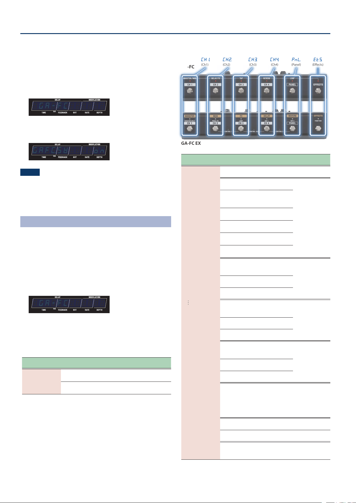
GA-FC switch
GA-FC
GA-FC EX
CH±CH±
(Ch1)
CH²CH²
(Ch2)
CH³CH³
(Ch3)
CH´CH´
(Ch4)
PnŸPnŸ
(Panel)
EtƭEtƭ
(Eects)
Parameter
[TIME] buttons
Value
[DEPTH] buttons
Explanation
CH1.Fn
(Ch1 Func)
CH´Fn
(Ch4 Func)
PnŸFn
(Panel Func)
EtƭFn
(Eects Func)
offoff
(o)
The GA-FC is not used.
bPŷtAPbPŷtAP
(BPM Tap)
BPM
Tap to input the
delay time.
d±²tAPd±²tAP
(DDL 1/DDL 2 Tap)
DDL 1 and DDL
2 (at the same
time)
d±ŸtAPd±ŸtAP
(DDL 1 Lch Tap)
L channel of
DDL 1
d±ƐtAPd±ƐtAP
(DDL 1 Rch Tap)
R channel of
DDL 1
d²ŸtAPd²ŸtAP
(DDL 2 Lch Tap)
L channel of
DDL 2
d²ƐtAPd²ƐtAP
(DDL 2 Rch Tap)
R channel of
DDL 2
d±²Sľd±²Sľ
(DDL 1/DDL 2 Switch)
DDL 1 and DDL
2 (at the same
time)
Turns the eect(s)
on/o.
d±Sľd±Sľ
(DDL 1 Switch)
DDL 1
d²Sľd²Sľ
(DDL 2 Switch)
DDL 2
d±²HLdd±²HLd
(DDL 1/DDL 2 Hold)
DDL 1 and DDL
2 (at the same
time)
The delay sound
repeats for as
long as you press
the switch (*1).
d±HoLdd±HoLd
(DDL 1 Hold)
DDL 1
d²HoLdd²HoLd
(DDL 2 Hold)
DDL 2
d±²NoNd±²NoN
(DDL 1/DDL 2 MOMENT)
DDL 1 and DDL
2 (at the same
time)
The delay sound
is output for as
long as you press
the switch (*1).
d±NoNd±NoN
(DDL 1 MOMENT)
DDL 1
d²NoNd²NoN
(DDL 2 MOMENT)
DDL 2
bYPASSbYPASS
(Bypass)
Turns the bypass on/o.
When this is on, the audio input is
outputted as-is.
Ø “Bypass circuit diagram (using
an external controller to activate
bypass)” (p. 30)
NEŷvPNEŷvP
(Memory up)
Switches to the next memory.
NEŷdnNEŷdn
(Memory down)
Switches to the previous memory.
NEŷnvNNEŷnvN
(Memory Number)
Selects the memories that you set
in CH±nvN–CH´nvN, PnŸnvN
and EtƭnvN.
29
Conguring the External Controllers
Parameter
[TIME] buttons
Value
[DEPTH] buttons
Explanation
CH±d±HLd
(CH1 DDL 1 Hold)
CH´d±HLd
(CH4 DDL 1 Hold)
PnŸd±HLd
(Panel DDL 1 Hold)
Etƭd±HLd
(Eects DDL 1 Hold)
Etƭd²HLd
(Eects DDL 2 Hold)
When CH±Fn–EtµFn is d±²HLd, d±HoLd,
d²HoLd
00–120120
Sets the Hold level.
CH±nvN
(CH1 Number)
CH´nvN
(CH1 Number)
PnŸnvN
(Panel Number)
EtƭnvN
(Eects Number)
This sets the memory number to recall for each GA-FC
switch.
Ʒÿ1Ʒÿ1–Źq2Źq2
A1–A4, B1–B4, C1–C92
CH±Nd
(CH1 Mode)
CH´Nd
(CH4 Mode)
PnŸNd
(Panel Mode)
EtƭNd
(Eects Mode)
When CH±Fn–EtµFn is oFF and tAP, NEŷvP,
NEŷdn, NEŷnvN are being used, this parameter is not
shown.
toGGLEtoGGLE
(Toggle)
Toggles between on and o each
time you operate the control.
NoNEntNoNEnt
(Moment)
Turns on only while you are pressing
down on the switch, and turns o
otherwise.
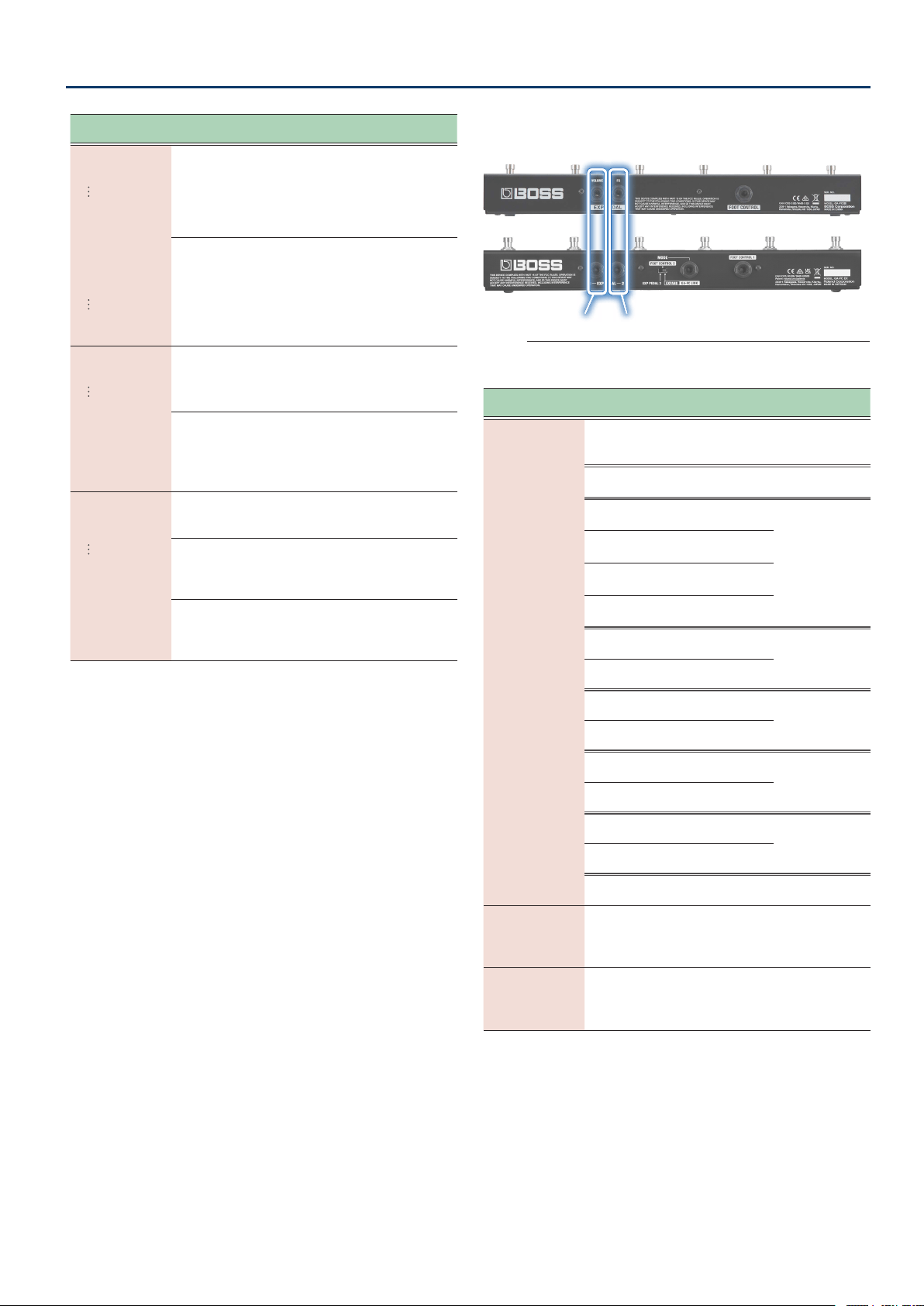
GA-FC pedal jack
GA-FC
GA-FC EX
E±FCE±FC
(Exp1 Func)
E±SƾFE±SƾF
(E1 Switch Func)
E²FCE²FC
(Exp2 Func)
E²SƾFE²SƾF
(E2 Switch Func)
Sets the functions of the EXP pedal.
Sets the functions of the footswitch.
Parameter
[TIME] buttons
Value
[DEPTH] buttons
Explanation
E±Fn
(Exp1 Func)
E²Fn
(Exp2 Func)
offoff
(o)
The EXP 1 and EXP 2 pedals
connected to the GA-FC are not
used.
FUFU
(Foot Volume)
Adjusts the foot volume level (Pedal
Position).
d±tiŷLd±tiŷL
(DDL 1 Time Lch)
L channel of
DDL 1
Adjusts the delay
time.
d±tiŷrd±tiŷr
(DD1 Time Rch)
R channel of
DDL 1
d²tiŷLd²tiŷL
(DDL 2 Time Lch)
L channel of
DDL 2
d²tiŷrd²tiŷr
(DD2 Time Rch)
R channel of
DDL 2
d±FbKd±FbK
(DDL 1 Feedback)
DDL 1
Adjusts the
amount of
feedback.
d²FbKd²FbK
(DDL 2 Feedback)
DDL 2
d±LEud±LEu
(DDL 1 Level)
DDL 1
Adjusts the
volume.
d²LEud²LEu
(DDL 2 Level)
DDL 2
d±ŷrAtd±ŷrAt
(DDL 1 Modulation Rate)
DDL 1
Adjusts the
modulation rate.
d²ŷrAtd²ŷrAt
(DDL 2 Modulation Rate)
DDL 2
d±ŷdPtd±ŷdPt
(DDL 1 Modulation Depth)
DDL 1
Adjusts the
modulation
depth.
d²ŷdPtd²ŷdPt
(DDL 2 Modulation Depth)
DDL 2
diƐLULdiƐLUL
(Direct Level)
Adjusts the direct level.
E±Nin
(Exp1 Min)
E²Nin
(Exp2 Min)
The variable range
diers depending
on the parameter.
Sets the minimum value for
the parameter controlled by an
expression pedal connected to the
GA-FC.
E±NAö
(Exp1 Max)
E²NAö
(Exp2 Max)
The variable range
diers depending
on the parameter.
Sets the maximum value for
the parameter controlled by an
expression pedal connected to the
GA-FC.
30
Conguring the External Controllers
Parameter
[TIME] buttons
Value
[DEPTH] buttons
Explanation
E±SƾF
(E1 Switch Func)
E²SƾF
(E2 Switch Func)
offoff
(o)
The GA-FC is not used.
bPŷtAPbPŷtAP
(BPM Tap)
BPM
Tap to input the
delay time.
d±²tAPd±²tAP
(DDL 1/DDL 2 Tap)
DDL 1 and DDL
2 (at the same
time)
d±ŸtAPd±ŸtAP
(DDL 1 Lch Tap)
L channel of
DDL 1
d±ƐtAPd±ƐtAP
(DDL 1 Rch Tap)
R channel of
DDL 1
d²ŸtAPd²ŸtAP
(DDL 2 Lch Tap)
L channel of
DDL 2
d²ƐtAPd²ƐtAP
(DDL 2 Rch Tap)
R channel of
DDL 2
d±²Sľd±²Sľ
(DDL 1/DDL 2 Switch)
DDL 1 and DDL
2 (at the same
time)
Turns the eect(s)
on/o.
d±Sľd±Sľ
(DDL 1 Switch)
DDL 1
d²Sľd²Sľ
(DDL 2 Switch)
DDL 2
d±²HLdd±²HLd
(DDL 1/DDL 2 Hold)
DDL 1 and DDL
2 (at the same
time)
The delay sound
repeats for as
long as you press
the switch.
d±HoLdd±HoLd
(DDL 1 Hold)
DDL 1
d²HoLdd²HoLd
(DDL 2 Hold)
DDL 2
d±²NoNd±²NoN
(DDL 1/DDL 2 MOMENT)
DDL 1 and DDL
2 (at the same
time)
The delay sound
is output for as
long as you press
the switch.
d±NoNd±NoN
(DDL 1 MOMENT)
DDL 1
d²NoNd²NoN
(DDL 2 MOMENT)
DDL 2
bYPASSbYPASS
(Bypass)
Turns the bypass on/o.
When this is on, the audio input is
outputted as-is.
NEŷvPNEŷvP
(Memory up)
Switches to the next memory.
NEŷdnNEŷdn
(Memory down)
Switches to the previous memory.
NEŷnvNNEŷnvN
(Memory Number)
Sets the memory number.
Parameter
[TIME] buttons
Value
[DEPTH] buttons
Explanation
E±Sƾd1HL
(E1 Switch DDL 1 Hold Level)
E±Sƾd2HL
(E1 Switch DDL 2 Hold Level)
E²Sƾd1HL
(E2 Switch DDL 1 Hold Level)
E²Sƾd2HL
(E2 Switch DDL 2Hold Level)
When E±SƾF, E²SƾF are d±²HLd, d±HoLd, or
d²HoLd, you can set the Hold Level.
00–120120
Sets the Hold level.
E±SƾN
(
E1 Switch
Mode)
E²SƾN
(
E2 Switch
Mode)
WhenE±SƾF, E²SƾF are oFF or tAP, this
parameter is not shown.
toGGLEtoGGLE
(Toggle)
Toggles between on and o each
time you operate the control.
NoNEntNoNEnt
(Moment)
Turns on only while you are pressing
down on the switch, and turns o
otherwise.
E±SƾnvN
(E1 Switch Number)
E²SƾnvN
(E2 Switch Number)
When E±SƾF, E²SƾF are NEŷnvN, this sets the
memory number to recall for E1 or E2 switch.
Ʒÿ1Ʒÿ1–Źq2Źq2
A1–A4, B1–B4, C1–C92
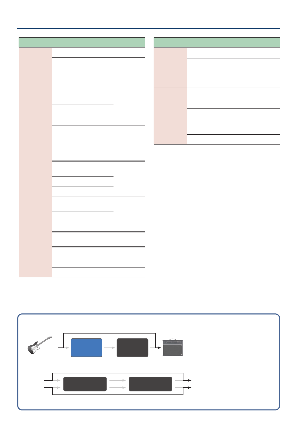
Bypass circuit diagram
(using an external controller to activate bypass)
FOOT
VOLUME
DDL 1/2
Guitar
AMP
DDL 1 (L/R) DDL 2 (L/R)
INPUT L OUTPUT L
INPUT R OUTPUT R
31
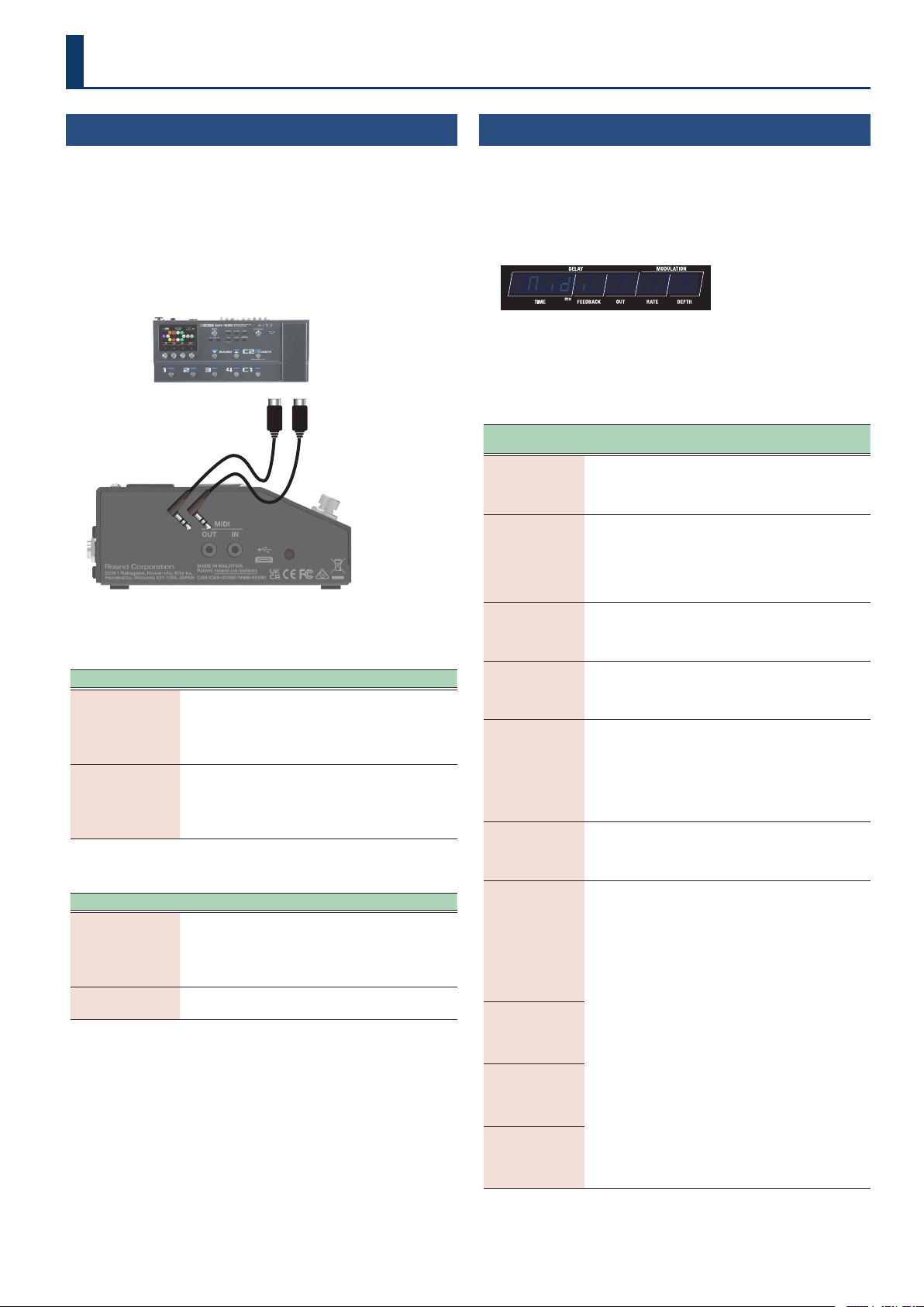
Connecting with an External MIDI Device
Connecting External Devices
Connect an external device to this unit via MIDI when you want to
exchange MIDI messages or synchronize to a clock signal.
MIDI (OUT/IN) jacks
Use TRS/TRS or TRS/MIDI connecting cables to connect this unit to an
external MIDI device.
Sold separately: TRS/MIDI connecting cable
BMIDI-5-35, BMIDI-1-35 or BMIDI-2-35
TRS/MIDI connecting cableTRS/MIDI connecting cable
With this unit, you can use MIDI to perform the following operations.
Operations from this unit
Operation Explanation
Transmit program
change messages
When you select a memory on this unit, the program
change message specied in MIDI PC MAP (p. 33) is
also transmitted. The external MIDI device that receives
this program change message then switches to the
corresponding settings.
Output control
change messages
The data when operating a footswitch or expression
pedal connected to the [CTL1] switch, the CTL 2, 3/
EXP 1 jack or the CTL 4, 5/EXP2/GA-FC jack is output as
control change messages. You can use these messages
to control the parameters of an external MIDI device.
Operations from an external MIDI device
Operation Explanation
Switch between
memory numbers
The memories of this unit switch when the
corresponding program change messages are received
from the external MIDI device.
This unit ignores Bank Select messages that are
received.
Receive control
change messages
This unit can receive control change messages to
control a specied parameter while you’re playing.
MIDI Settings
(MIDI)
1. Press the [SETUP] button.
The parameter to set is shown in the display.
2. Use the [TIME] buttons to select “NidiNidi”, and press the
[SETUP] (ENTER) button.
¸¸¸¸¸¸¸¸¸¸¸¸$Nidi
3. Use the [TIME] buttons to select a parameter, and then
use the [DEPTH] buttons to change the value.
MIDI parameters
Parameter
[TIME] buttons
Value
[DEPTH] buttons
Explanation
rŶCH
(Rx Channel)
offoff
(o)
Cƶ1Cƶ1––Cƶ1ļCƶ1ļ
(CH.1–CH.16)
Species the MIDI receive channel.
When this is “oFF”, channel
messages are not received.
tŶCH
(Tx Channel)
offoff
(o)
Cƶ1Cƶ1––Cƶ1ļCƶ1ļ
(CH.1–CH.16)
rörö
(Rx)
Species the MIDI transmit channel.
When this is “oFF”, channel
messages are not transmitted.
When this is set to “rö”, the
transmit channel is set to be the
same as the receive channel.
PC.in
(PC IN)
offoff
(o)
onon
(on)
Species whether program changes
are received (on) or not received
(oFF).
PC.ovt
(PC OUT)
offoff
(o)
onon
(on)
Species whether program changes
are transmitted (on) or not
transmitted (oFF).
CC.in
(CC IN)
offoff
(o)
onon
(on)
Species whether control change
messages are received (on) or not
(oFF).
This unit can use CC messages
it receives to control the same
operations as a knob or footswitch
via MIDI.
CC.ovt
(CC OUT)
offoff
(o)
onon
(on)
Species whether control changes
are transmitted (on) or not
transmitted (oFF).
d±tiNƹL
(DDL 1 Time L)
d±tiNƹr
(DDL 1 Time R)
d²tiNƹL
(DDL 2 Time L)
d²tiNƹr
(DDL 2 Time R)
oFFoFF
(o)
cc01cc01––cc31cc31, ,
(CC01–CC31)
ccb4ccb4––ccq5ccq5
(CC64–CC95)
Species the controller number
corresponding to each controller.
d±Fbk
(DDL 1 Feedback)
d²Fbk
(DDL 2 Feedback)
d±ovt
(DDL 1 Out)
d²ovt
(DDL 2 Out)
d±NƞrAt
(DDL 1 Modulation Rate)
d²NƞrAt
(DDL 2 Modulation Rate)
32
Connecting with an External MIDI Device
Parameter
[TIME] buttons
Value
[DEPTH] buttons
Explanation
d±NƞdPt
(DDL 1 Modulation Depth)
d²NƞdPt
(DDL 2 Modulation Depth)
oFFoFF
(o)
cc01cc01––cc31cc31, ,
(CC01–CC31)
ccb4ccb4––ccq5ccq5
(CC64–CC95)
Species the controller number
corresponding to each controller.
d±Ft$on
(DDL 1 Filter on)
d²Ft$on
(DDL 2 Filter on)
d±tN$on
(DDL 1 Time on)
d²tN$on
(DDL 2 Time on)
d±PH$on
(DDL 1 Phase on)
d²PH$on
(DDL 2 Phase on)
d±Nd$on
(DDL 1 Mod on)
d²Nd$on
(DDL 2 Mod on)
d±ƱP$on
(DDL 1 Feedback Phase on)
d²ƱP$on
(DDL 2 Feedback Phase on)
d±²tAp
(
DDL 1/DDL 2 Tap
)
d±ŸtAp
(
DDL 1 Lch Tap
)
d±ƐtAp
(
DDL 1 Rch Tap
)
d²ŸtAp
(
DDL 2 Lch Tap
)
d²ƐtAp
(
DDL 2 Rch Tap
)
d±HoLd
(
DDL 1 Hold)
d²HoLd
(
DDL 2 Hold)
d±Non
(
DDL 1 Moment
)
d²Non
(
DDL 2 Moment
)
FžPŸPoS
(Foot Volume Pedal Position)
diƐLEUL
(Direct Level)
CtL1
(Control 1)
CtL2
(Control 2)
CtL3
(Control 3)
CtL4
(Control 4)
CtL5
(Control 5)
EöP1
(Exp 1)
EöP2
(Exp 2)
bYPASS
(Bypass)
d±Sľ
(DDL 1 Switch)
d²Sľ
(DDL 2 Switch)
Parameter
[TIME] buttons
Value
[DEPTH] buttons
Explanation
SYnC
(Sync)
Species the input to which the tempo clock is
synchronized.
Guaranteed operating range: 40–250 BPM
intint
(Internal)
Synchronizes with the internal
tempo.
vSbvSb
(USB)
Synchronizes to the MIDI clocks
received via the USB port.
NidiNidi
(MIDI)
Synchronizes to the MIDI clocks
received via the MIDI IN jack.
AvtoAvto
(Auto)
This unit normally operates using
its internal tempo, but synchronizes
the tempo to the MIDI clock if MIDI
clock data is received via the USB
port or the MIDI IN connector.
* When both USB and MIDI are input, USB is
given priority.
rTŷSrC
(Real Time Message Source)
Species the source of real-time messages that are
output to the MIDI OUT jack or USB port.
intint
(Internal)
Internal real-time messages are
used as the clock source.
vSbvSb
(USB)
Real-time messages from the USB
port are used as the clock source.
NidiNidi
(MIDI)
Real-time messages from the MIDI
IN jack are used as the clock source.
NidńtHrv
(MIDI Thru)
This species the jack from which to output the MIDI
messages that are received at the MIDI IN jack.
oFFoFF
(o)
Not transmitted.
vSbvSb
(USB)
Transmitted from the USB port.
NidNid
(MIDI)
Transmitted from the MIDI OUT jack.
ŜNŜN
(USB, MIDI)
Transmitted from the USB port and
the MIDI OUT jack.
vSƼtHrv
(USB Thru)
This species the jack from which to output the MIDI
messages that are received at the USB port.
oFFoFF
(o)
Not transmitted.
vSbvSb
(USB)
Transmitted from the USB port.
NidNid
(MIDI)
Transmitted from the MIDI OUT jack.
ŜNŜN
(USB, MIDI)
Transmitted from the USB port and
the MIDI OUT jack.
dEUiCƹid
(Device ID)
1717–3232
Sets the device ID number for
transmitting and receiving system
exclusive messages.
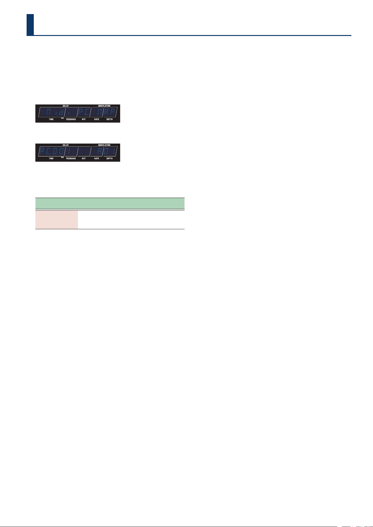
33
You can use the program change map to customize which memories
on the SDE-3000D correspond to which program change messages
sent from an external MIDI device.
1. Press the [SETUP] button.
The parameter to set is shown in the display.
2. Use the [TIME] buttons to select “Nidi$PC$NAPNidi$PC$NAP”.
¸¸¸¸¸¸¸¸¸¸¸¸$Nidi$PC$NAP
3. Press the [SETUP] button.
¸¸¸¸¸¸¸¸¸¸¸¸PŹ001$$$$Ʒ01
4. Use the [TIME] buttons to select the program number,
and use the [DEPTH] buttons to set the memory
number.
Parameter
[TIME] buttons
Value
[DEPTH] buttons
Explanation
PŹ001–PŹ128
Ʒ01Ʒ01–Źq2Źq2
This sets the memory number
that corresponds to the
program number.
Conguring the Program Change Map for the Memories
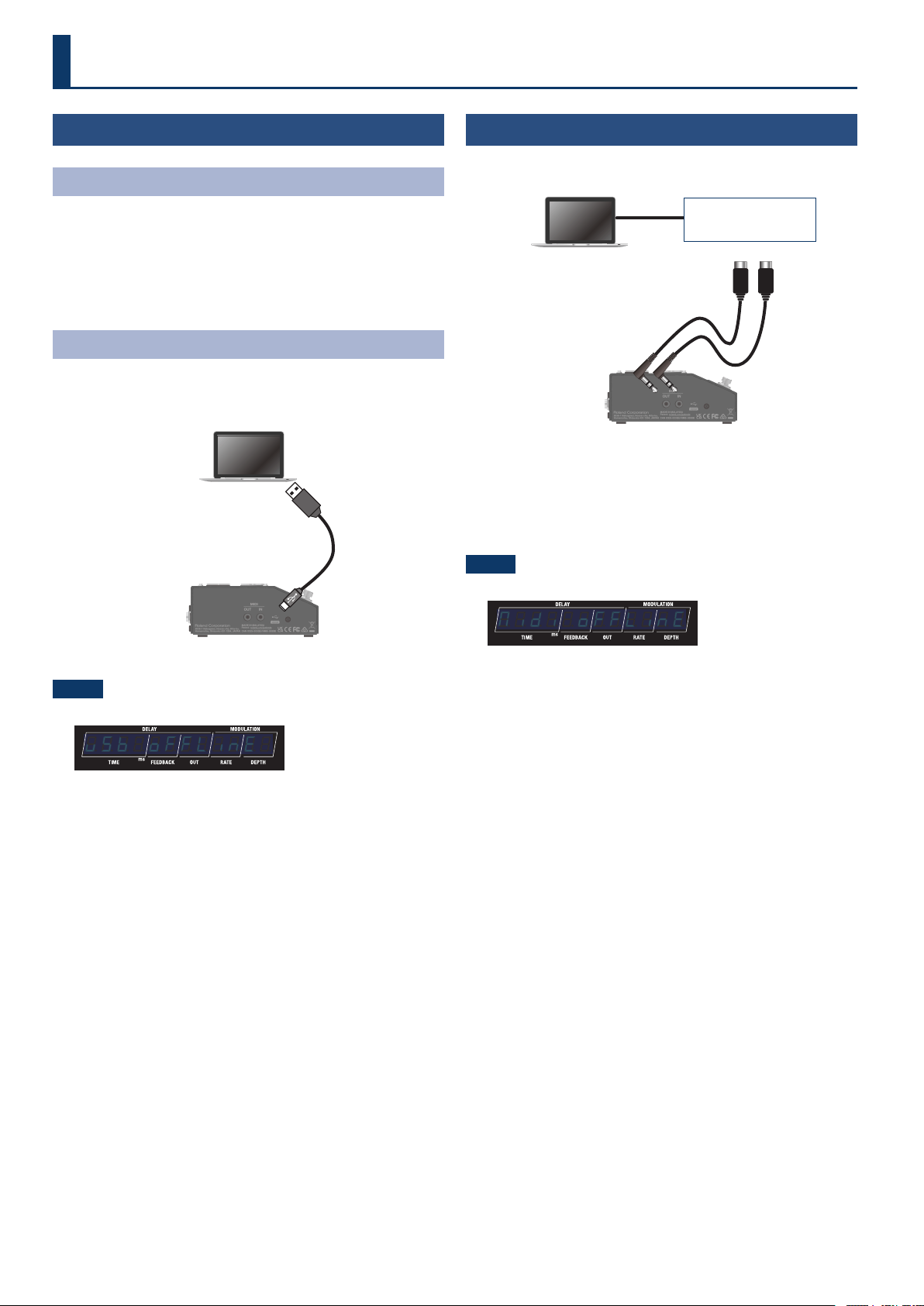
34
Using the USB Port
(USB Type-C®)
Installing the USB Driver
You must install the USB driver before connecting this unit to a
computer.
Download the USB driver from the BOSS website.
Install this special driver before making a USB connection. For details,
refer to Readme.htm in the downloaded le.
Ø https://www.boss.info/support/
Connecting to a Computer
1. Connect your computer using a commercially available
USB cable that supports USB 2.0.
SDE-3000D
Computer
NOTE
An error message is shown when the USB connection is severed.
¸¸¸¸¸¸¸¸¸¸¸¸vSb$oFFLinE
Using the MIDI Jacks on the Side Panel
Use TRS/TRS or TRS/MIDI connecting cables to connect this unit to an
external MIDI device.
Computer
TRS/MIDI connecting cableTRS/MIDI connecting cable
SDE-3000D
USB MIDI
interface
Sold separately:
TRS/TRS connecting cable
BCC-1-3535, BCC-2-3535
TRS/MIDI connecting cable
BMIDI-5-35, BMIDI-1-35, BMIDI-2-35
NOTE
An error message is shown when the MIDI IN connection is severed.
¸¸¸¸¸¸¸¸¸¸¸¸Nidi$oFFLinE
Check whether there is a problem with the MIDI cable connected to
the MIDI IN jack of this unit, or whether the MIDI cable has not come
loose.
Connecting to a Computer
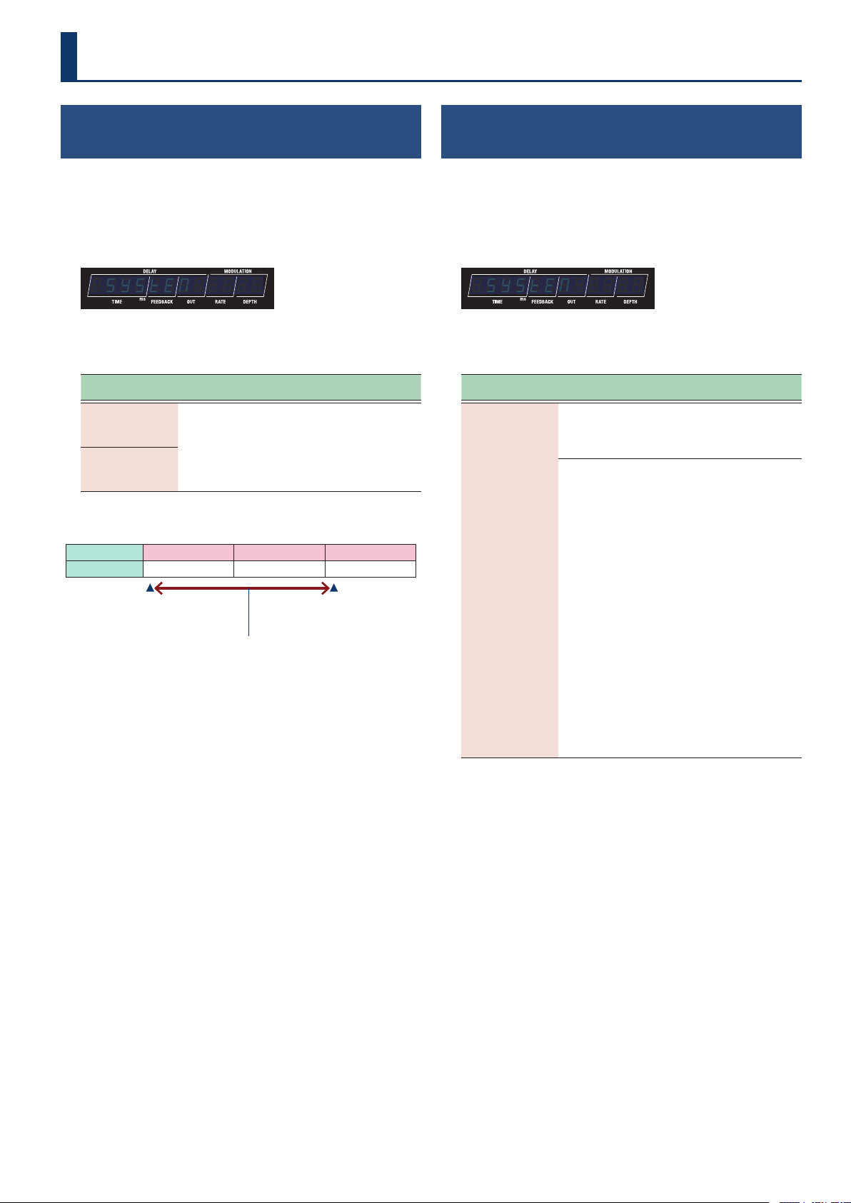
35
System Settings
Conguring the Range of Memories Selectable
with the Foot Pedal
(Memory Extent)
1. Press the [SETUP] button.
The parameter to set is shown in the display.
2. Use the [TIME] buttons to select “SYSTENSYSTEN”, and press
the [SETUP] (ENTER) button.
¸¸¸¸¸¸¸¸¸¸¸¸$SYSTEN
3. Use the [TIME] buttons to select a parameter, and then
use the [DEPTH] buttons to change the value.
Parameter
[TIME] buttons
Value
[DEPTH] buttons
Explanation
NEŷNin
(Memory Min)
Ʒ01Ʒ01–Źq2Źq2
This sets the range of memories
that you can select with the foot
pedal.
NEŷNAö
(Memory Max)
Example
Bank A B C
Memory 1
…
4 1
…
4 1
…
92
NEŷNin
(Memory Min)
NEŷNAö
(Memory Max)
Range of memories that can be selected using the pedal (A.01–C.01)
Inheriting EXP Pedal Setting when Switching
Memory
(EXP Hold)
1. Press the [SETUP] button.
The parameter to set is shown in the display.
2. Use the [TIME] button to select “SYSTEN”, and then
press the [SETUP] button.
¸¸¸¸¸¸¸¸¸¸¸¸$SYSTEN
3. Use the [TIME] buttons to select a parameter, and then
use the [DEPTH] buttons to change the value.
Parameter
[TIME] button
Value
[DEPTH] button
Explanation
EXP1.PL.Hd
(EXP 1 Pedal Hold)
EXP2.PL.Hd
(EXP 2 Pedal Hold)
oFFoFF
The operational status of the
E±.FnC and E²FnC is not
carried over when memories are
switched.
onon
The operational status of the EXP
1 and EXP 2 is carried over when
memories are switched, if the
E±.FnC and E²FnC setting is
the same as the previous memory.
For example, if EXP PEDAL
FUNCTION is set to FOOT VOLUME
in both memories (the one before
and the one after the change),
the volume corresponding to
the position (angle) the pedal
is in at the time of the memory
change will be maintained after
the memory change. On the
other hand, if the memory being
changed to is set to WAH, the
volume is in accordance with the
value set within the memory,
and you’ll obtain a wah eect
that is in accordance with a value
that reects the current position
(angle) of the pedal.
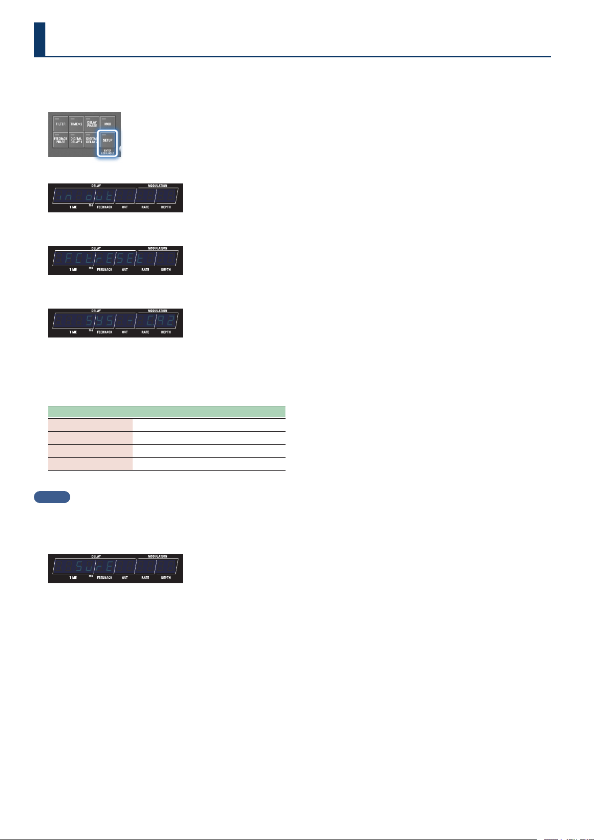
36
Restoring the Unit to the Factory Settings
Here’s how to restore the SDE-3000D to its factory settings.
1. Press the [SETUP] button.
The parameter to set is shown in the display.
¸¸¸¸¸¸¸¸¸¸¸¸in;ovt
2. Use the [TIME] buttons to select “FCƸrESEtFCƸrESEt”.
¸¸¸¸¸¸¸¸¸¸¸¸$FCƸrESEt
3. Press the [SETUP] button.
¸¸¸¸¸¸¸¸¸¸¸¸$$$SYS$-$ŹQ2
4. Use the [TIME] and [DEPTH] buttons to select the areas
(ranges) aected by the factory reset.
Press the [â] (EXIT) button if you want to cancel and return to the
menu.
Target Explanation
SYS
System settings
Ʒ01–Ʒ04
1–4 in bank A
Ƽ01–Ƽ04
1–4 in bank B
Ź01–Źq2
1–92 in bank C
MEMO
To reset everything, select “SYS$-$Źq2”.
5. Press the [BANK A] button.
A conrmation message appears.
¸¸¸¸¸¸¸¸¸¸¸¸$$SvrE
“SURE” blinks in the display.
6. Press the [BANK A] button to execute the factory reset.
Once the factory reset is complete, the unit returns to play screen.
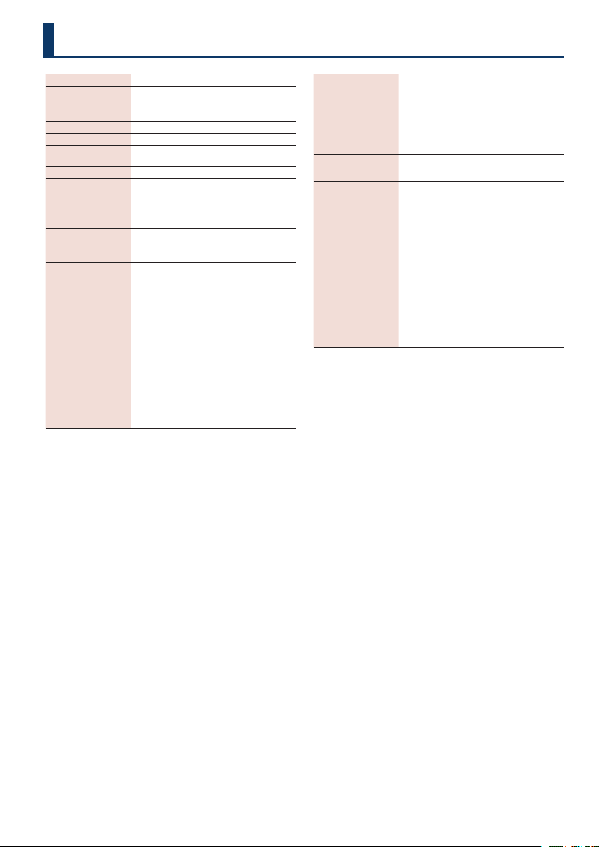
37
Sampling Frequency
48 kHz
AD Conversion
24 bits + AF method
* AF method (Adaptive Focus method) This is a proprietary
method from Roland & BOSS that vastly improves the signal-
to-noise (SN) ratio of the AD and DA converters.
DA Conversion
32 bits
Processing
32-bit oating point
Eects
SDE-3000 STEREO DELAY x 2
FOOT VOLUME
Memory
100
Nominal Input Level
INPUT (L/MONO, R): -10 dBu
Maximum Input Level
INPUT (L/MONO, R): +12 dBu
Input Impedance
INPUT (L/MONO, R): 1 MΩ
Nominal Output Level
OUTPUT (L/MONO, R): -10 dBu
Output Impedance
OUTPUT (L/MONO, R): 1 kΩ
Recommended Load
Impedance
OUTPUT (L/MONO, R): 10 kΩ or greater
Controls
[TIME] buttons
[FEEDBACK] buttons
[OUT] buttons
[RATE] buttons
[DEPTH] buttons
[1]–[4] buttons
[BANK A] button
[BANK B] button
[
ã
] button
[
â
] button
[FILTER] button
[TIME×2] button
[DELAY PHASE] button
[MOD] button
[FEEDBACK PHASE] button
[DIGITAL DELAY1] button
[DIGITAL DELAY2] button
[SETUP] button
Display
7 segments, 12 digits LED
Connectors
INPUT (L/MONO, R) jack: 1/4-inch phone type
OUTPUT (L/MONO, R) jacks: 1/4-inch phone type
CTL2,3/EXP1 jack: 1/4-inch TRS phone type
CTL4,5/EXP2/GA-FC jack: 1/4-inch TRS phone type
MIDI (IN, OUT) jacks: Stereo miniature phone type
USB port: USB Type-C®
DC IN jack
Power Supply
AC Adaptor
Current Draw
450 mA
Dimensions
199 (W) x 135 (D) x 54 (H) mm (including rubber
foot)
7-7/8 (W) x 5-3/8 (D) x 2-1/8 (H) inches (including
rubber foot)
Weight
(excluding AC adaptor)
1.1 kg
2 lbs 7 oz
Accessories
AC adaptor (PSB-1U + AC Cord Set)
STARTUP GUIDE
Leaet “USING THE UNIT SAFELY”
Rubber foot x 4
Options
Footswitch: FS-5U, FS-5L
Dual footswitch: FS-6, FS-7
Expression Pedal: EV-30, FV-500L, FV-500H, Roland
EV-5
Foot Controller :GA-FC, GA-FC EX
MIDI/TRS connecting cable: BMIDI-5-35,
BMIDI-1-35, BMIDI-2-35, BCC-1-3535, BCC-2-3535
Main Specications
* 0 dBu = 0.775 Vrms
* This document explains the specications of the product at the time that the document was issued. For the latest information, refer to the
Roland website.
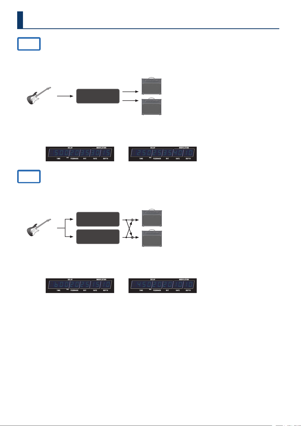
38
Preset List
A.01
The standard delay setting.
This is a short delay with DDL 1 set to 500 msec and DDL 2 set to 250 msec.
The delay gives a feeling of depth by combining two delays connected in series.
STRUCTURE: SERI
DRY+WET L
DRY+WET R
Guitar
AMP
DDL 1 (L/R)
ON
¸¸¸¸¸¸¸¸¸¸¸¸$50020353015 ¸¸¸¸¸¸¸¸¸¸¸¸$25025354010
DDL 1 parameter
DDL 1 SW: ON
DDL 1 TYPE: STEREO
DDL 1 TIME LINK: ON
DDL 2 parameter
DDL 2 SW: OFF
DDL 2 TYPE: STEREO
DDL 2 TIME LINK: ON
A.02
A delay sound that gives a dotted eighth note feel, with the delays connected in parallel.
DDL 1 is set to 600 msec, and DDL 2 is set to 450 msec.
STRUCTURE: PARA1
DRY+WET L
DRY+WET R
Guitar
AMP
DDL 1 (L/R)
DDL 2 (L/R)
ON
ON
¸¸¸¸¸¸¸¸¸¸¸¸$b0020251510 ¸¸¸¸¸¸¸¸¸¸¸¸$45020201010
DDL 1 parameter
DDL 1 SW: ON
DDL 1 TYPE: STEREO
DDL 1 TIME LINK: ON
DDL 2 parameter
DDL 2 SW: ON
DDL 2 TYPE: STEREO
DDL 2 TIME LINK: ON
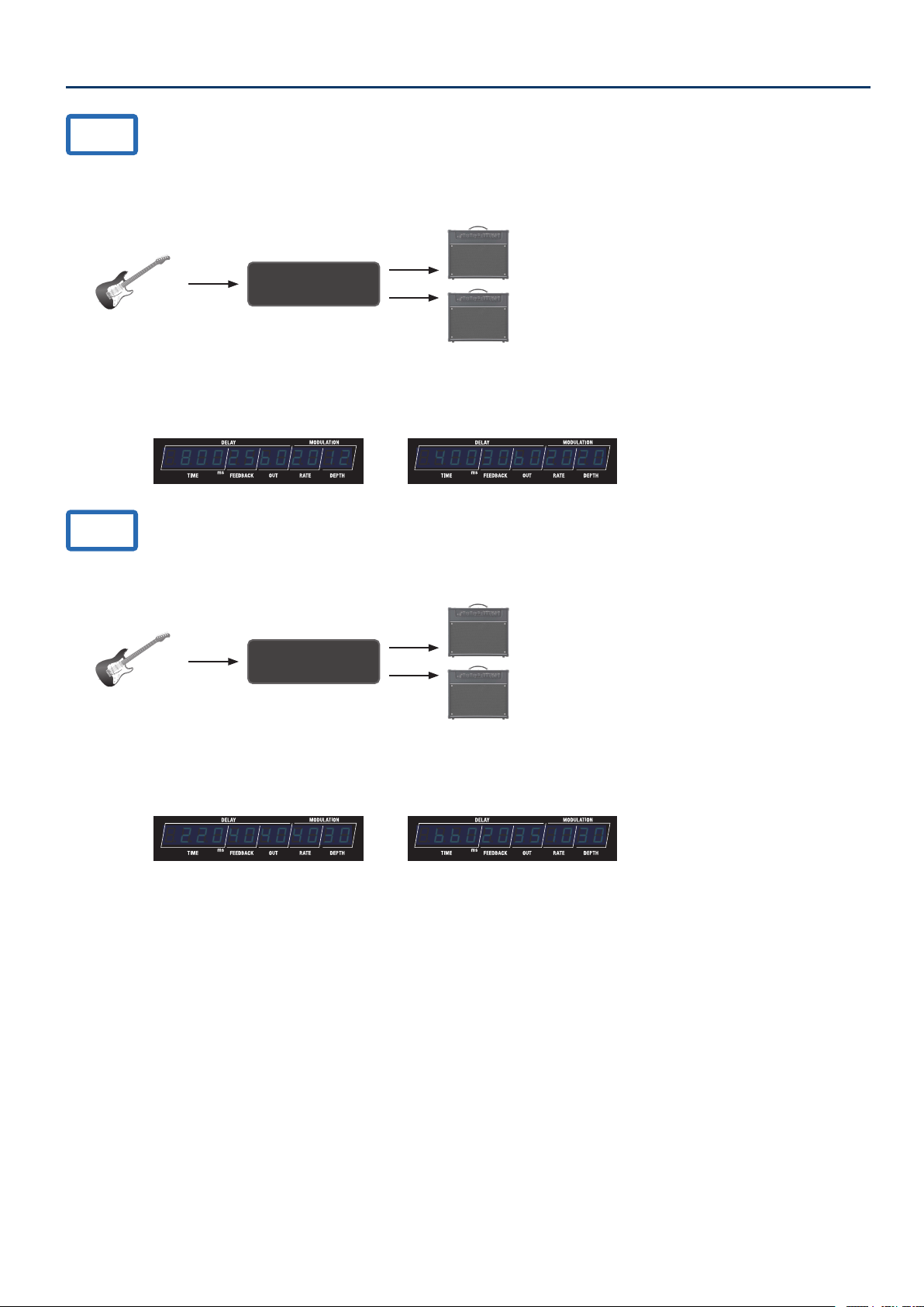
39
Preset List
A.03
A delay with DDL 1 set to 800 msec (long) and DDL 2 set to 400 msec (medium).
Turn DDL 2 on for a dreamlike long delay.
STRUCTURE: SERI
DRY+WET L
DRY+WET R
Guitar
AMP
DDL 1 (L/R)
ON
¸¸¸¸¸¸¸¸¸¸¸¸$80025b02012 ¸¸¸¸¸¸¸¸¸¸¸¸$40030b02020
DDL 1 parameter
DDL 1 SW: ON
DDL 1 TYPE: STEREO
DDL 1 TIME LINK: ON
DDL 2 parameter
DDL 2 SW: OFF
DDL 2 TYPE: STEREO
DDL 2 TIME LINK: ON
A.04
A delay sound with two delays (DDL 1: 220 msec, DDL 2: 660 msec) connected in parallel.
STRUCTURE: SERI
DRY+WET L
DRY+WET R
Guitar
AMP
DDL 1 (L/R)
ON
¸¸¸¸¸¸¸¸¸¸¸¸$22040404030 ¸¸¸¸¸¸¸¸¸¸¸¸$bb020351030
DDL 1 parameter
DDL 1 SW: ON
DDL 1 TYPE: STEREO
DDL 1 TIME LINK: ON
DDL 2 parameter
DDL 2 SW: ON
DDL 2 TYPE: STEREO
DDL 2 TIME LINK: ON
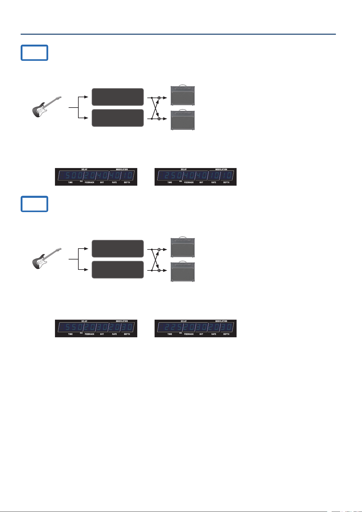
40
Preset List
B.01
A delay sound with two delays connected in parallel (DDL 1: modulation delay, 500 msec; DDL 2: short delay, 250 msec).
STRUCTURE: PARA1
DRY+WET L
DRY+WET R
Guitar
AMP
DDL 1 (L/R)
DDL 2 (L/R)
ON
ON
¸¸¸¸¸¸¸¸¸¸¸¸$50020404010 ¸¸¸¸¸¸¸¸¸¸¸¸$25040401010
DDL 1 parameter
DDL 1 SW: ON
DDL 1 TYPE: STEREO
DDL 1 TIME LINK: ON
DDL 2 parameter
DDL 2 SW: ON
DDL 2 TYPE: STEREO
DDL 2 TIME LINK: ON
B.02
A delay sound with two modulation delays connected in parallel (DDL 1: 550 msec, DDL 2: 225 msec).
STRUCTURE: PARA1
DRY+WET L
DRY+WET R
Guitar
AMP
DDL 1 (L/R)
DDL 2 (L/R)
ON
ON
¸¸¸¸¸¸¸¸¸¸¸¸$55020302030 ¸¸¸¸¸¸¸¸¸¸¸¸$22520302030
DDL 1 parameter
DDL 1 SW: ON
DDL 1 TYPE: STEREO
DDL 1 TIME LINK: ON
DDL 2 parameter
DDL 2 SW: ON
DDL 2 TYPE: STEREO
DDL 2 TIME LINK: ON
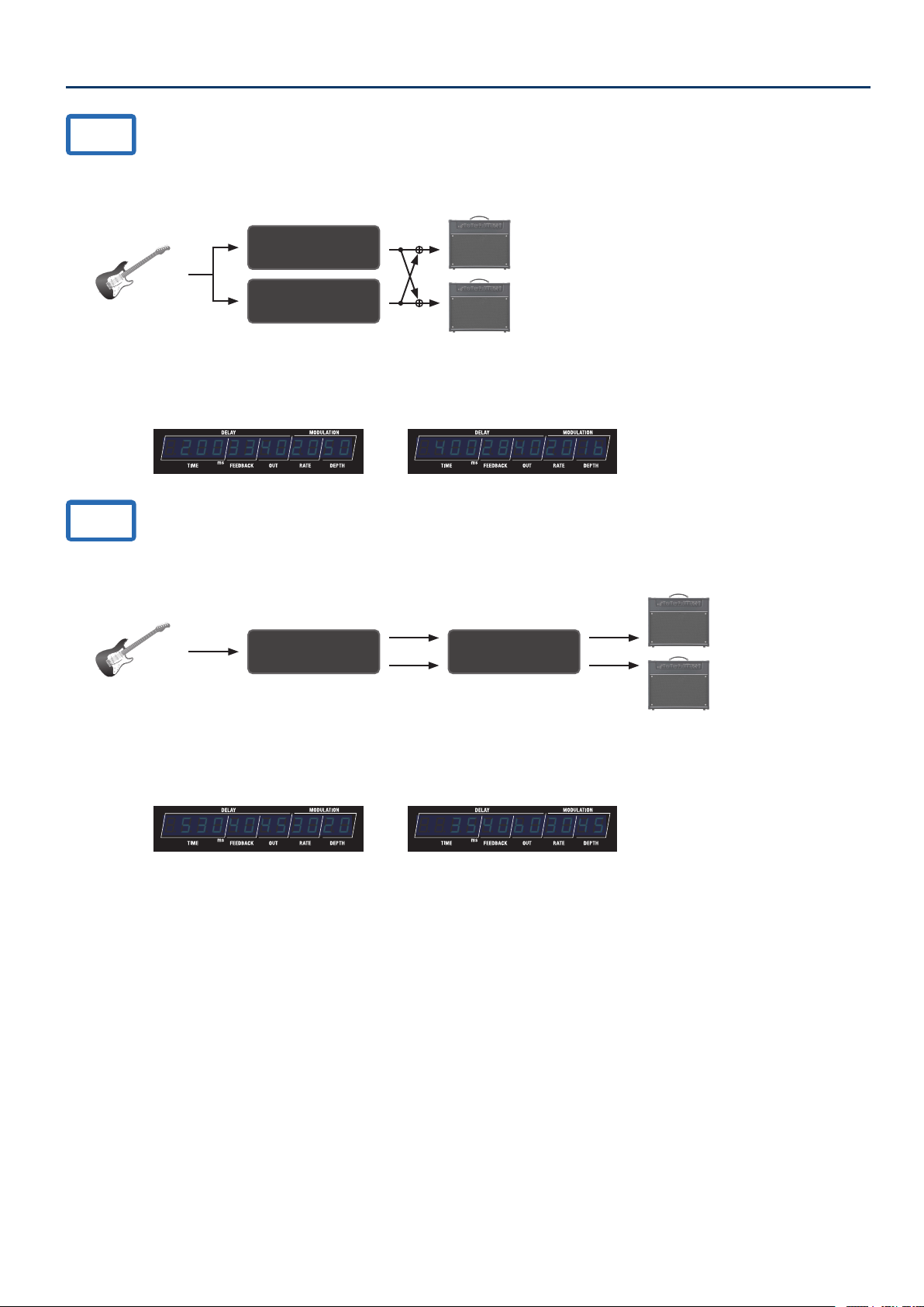
41
Preset List
B.03
A delay sound that combines a lter and modulation.
STRUCTURE: PARA1
DRY+WET L
DRY+WET R
Guitar
AMP
DDL 1 (L/R)
DDL 2 (L/R)
ON
ON
¸¸¸¸¸¸¸¸¸¸¸¸$20033402050 ¸¸¸¸¸¸¸¸¸¸¸¸$4002840201b
DDL 1 parameter
DDL 1 SW: ON
DDL 1 TYPE: STEREO
DDL 1 TIME LINK: ON
DDL 2 parameter
DDL 2 SW: ON
DDL 2 TYPE: STEREO
DDL 2 TIME LINK: ON
B.04
A short reverb sound, with the DDL 2 delay (35 msec) added to the DDL 1 delay (530 msec).
STRUCTURE: SERI
DRY+WET L
DRY+WET R
Guitar
AMP
DDL 1 (L/R) DDL 2 (L/R)
ON ON
¸¸¸¸¸¸¸¸¸¸¸¸$53040453020 ¸¸¸¸¸¸¸¸¸¸¸¸$$3540b03045
DDL 1 parameter
DDL 1 SW: ON
DDL 1 TYPE: STEREO
DDL 1 TIME LINK: ON
DDL 2 parameter
DDL 2 SW: ON
DDL 2 TYPE: STEREO
DDL 2 TIME LINK: ON
