Loading ...
Loading ...
Loading ...
4
2 Unit Preparation
• Inspect the exterior of the unit for shipping damage.
• Unit should never operate while the building is still in construction.
• Unit is shipped with its door covered with a cardboard for protection during construction. Leave the cardboard on until painting.
2.1 Choose an Appropriate Location for the Unit
• Within an area of the house where the ambient temperature is kept between 50°F and 135°F;
• Away from living areas (dining room, living room, bedroom), if possible to reduce noise level;
• So as to provide easy access to the interior cabinet for maintenance;
• Close to an exterior wall, so as to limit the length of the insulated exible ducts to and from the unit;
• Away from hot chimneys, electrical panel and other re hazards;
• Within 28" of a power source (standard outlet, ERVS100S unit only).
2.2 Electrical Connection Type (Cord Connected or Hardwired)
• According to your needs and applicable codes, make sure you have the appropriate model (ERVS100S: cord connected unit
and ERVS100S-HW: hardwired unit).
3 Installation
3.1 Positioning the Unit
• Unit can be installed between 24” on-center trusses, on top of 24” on-center trusses in reversed position or under the ceiling,
using brackets. A set of 4 brackets is included in the hardware kit, along with the necessary screws.
• The unit shall be connected to a 15-amp electrical circuit. It is recommended to label the circuit to identify this system as the
Fresh Air System. If cord connected (ERVS100S unit only), a standard 3-prong electrical outlet has to be available within 28”
of the unit.
• Allow a 12” clearance for the door, core and lters to be removed for maintenance.
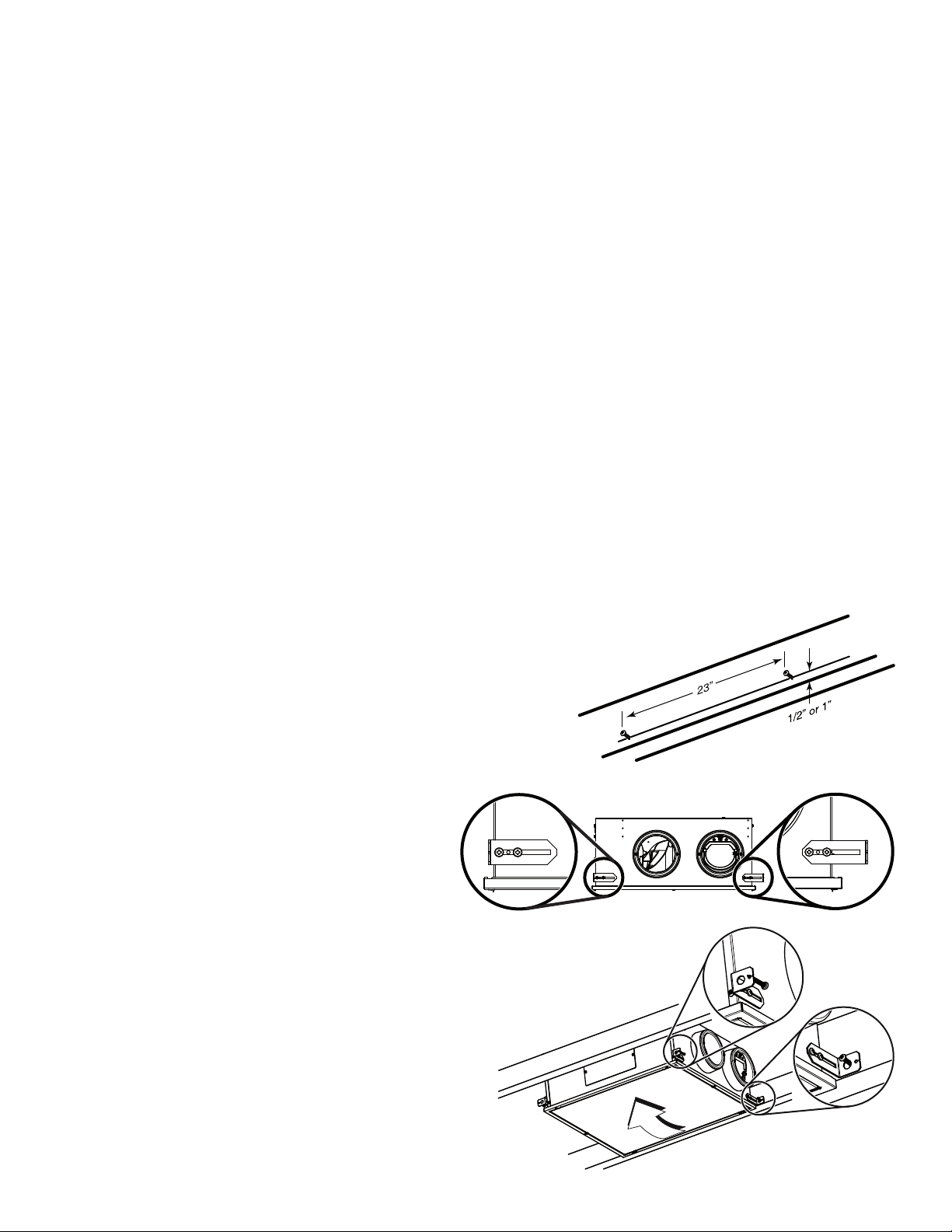
3.1.1 Installation in the ceiling (between 24” on-center trusses)
1. Trace a level line on both trusses, at 1/2” or 1” from the bottom, for
the unit bracket location (1/2” will allow the unit door perimeter to
lay on ceiling material while 1” will result in flush mount installation;
see A and B in next page). On one truss, screw half way on level line
two no. 8 x 1½” provided screws, leaving 23” between each other.
2. Mount the 4 brackets to the unit as illustrated at
right, using two no.10 x 5/8" screws provided for
each bracket.
TIP: Screw half way the screws to allow adjusment
between trusses, see insets at right (left shows the
minimum distance and right the maximum distance.
3. Hang the lightest side of the unit on the screws mounted
on the truss using the larger holes of the brackets.
4. Lift the other side of the unit and secure it to the other
truss using one no. 8 x 1½” screw per bracket, inserted
through the smaller hole of the brackets.
VD0391A
VD0394
VD0390
Unit must be installed in the horizontal orientation as shown in section 3.1.
Loading ...
Loading ...
Loading ...