Loading ...
Loading ...
Loading ...
16
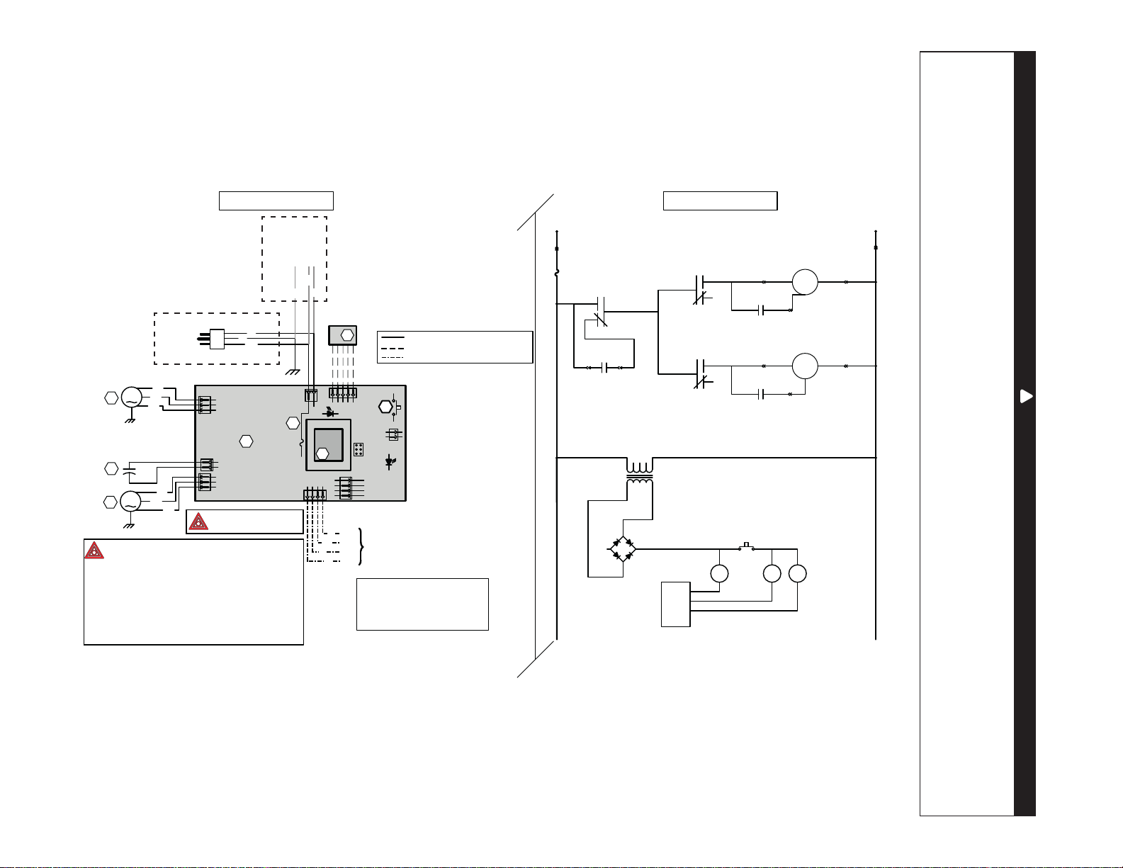
7 Wiring Diagram
WARNING
• Risk of electric shocks. Before performing any maintenance or servicing, always turn power off at service panel
or disconnect the unit from its power source.
• This product is equipped with an overload protection (fuse). A blown fuse indicates an overload or a short-circuit
situation. If the fuse blows, unplug the product from the outlet or, if hard-wired, turn off power at service panel.
Discontinue using the unit and contact technical support.
!
L
INE
N
EUTRAL
120 VAC
J1-1
J1-2
M
F1
LOGIC DIAGRAM
M
C2 MOTOR SPEED
SUPPLY FAN
MOTOR M2
K2
K1
K3
J4-1
J4-2
J4-3
EXHAUST MOTOR
CAPACITOR
SUPPLY MOTOR
CAPACITOR
J3-1
J3-2
J3-3
J2-1 J2-2
T1
9.5 VAC
S1 EMBEDDED
DOOR SWITCH
K2
K1
K3
CPU
WIRING DIAGRAM
LINE VOLTAGE FACTORY WIRING
CLASS 2 LOW VOLTAGE FACTORY WIRING
CLASS 2 LOW VOLTAGE FIELD WIRING
RH SENSOR
A2
S1
DOOR INTERLOCK
SWITCH
1
2
1
2
1
2
3
1
2
3
J4
J2
J3
A1
ELECTRONIC
ASSEMBLY
F1
3A
3AG TYPE
1
2
J1
J6
12345
120 VAC
60 Hz
W
G
BK
T1
J7
ICP
J9
4
3
2
1
J8
J5
1234
OVERRIDE SWITCH
(OPTIONAL)
G
BK
Y
R
OC
OL
I
STB
M1
M2
C2
BK
BL
BR
BK
BL
BR
COLOR CODE
BLACK
BLUE
BROWN
GREEN
BK
BL
BR
G
RED
WHITE
YELLOW
R
W
Y
Critical characteristic.
NOTES
1.
Protected against fire with
UL listed/CSA Certified line fuse.
2. If any of the original wire, as supplied, must
be replaced, use the same equivalent wire.
3. Field wiring must comply with applicable
codes, ordinances and regulations.
4. Remote controls (class 2 circuit) available,
see instruction manual.
5. Furnace fan circuit must be class 2 circuit only.
VE0472A
EXHAUST FAN
MOTOR M1
ref: 24605_REV-A
W
BK
G
120 VAC
60 Hz
Ground
Line
Neutral
ERVS100S
ERVS100S-HW
-
+
~
~
Loading ...
Loading ...
Loading ...