Loading ...
Loading ...
Loading ...
18
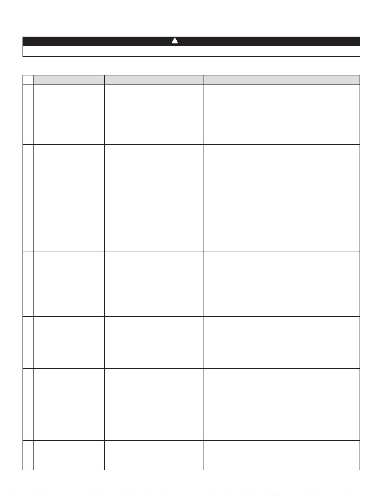
9 Troubleshooting
If the unit does not work properly, reset the unit by removing power at service panel or unplugging it for one minute and then
restore power at service panel or replug the unit. If it still not working properly, refer to table below.
PROBLEMS POSSIBLE CAUSES YOU SHOULD TRY THIS
1 Unit does not start.
• No power to power outlet or to
wires on power cable.
• Unit door not properly closed.
• PCB plastic holder tabs unclipped.
• Check the breaker in the distribution panel.
• ERVS100S only: Test the power outlet with another electrical
device (e.g.: a lamp). If it does not work, call an electrician.
• ERVS100S-HW only: Use a voltmeter to check power cable
wires. If there is no voltage detected, call an electrician.
• Ensure the unit door is properly closed.
• Ensure the PCB plastic holder tabs are engaged in their
slots and the PCB is well seated on its holder.
2
LED blinks rapidly on
push button and unit
(motor error).
• Motor harness damaged or
misconnected.
• Defective PCB, motor assembly or
low speed capacitor.
• Check both motor harness connections, ensure that
connectors are connected to their appropriate places, the
wires are not damaged and connector pins are not corroded.
• Open the door and push on door switch spring to reset the
error and activate the unit self test during booting sequence.
Both motors must start in high speed for 10 seconds, then go
on low speed for 10 seconds. If both motors do not go on
high speed; replace the PCB.
• If one motor does not start on high speed, inverse both motors
connection and start again the self test; if the motor still not
start on high speed, replace the motor asembly and if the
problem is now on the other motor, replace the PCB.
• If both motors run in high but not in low speed, replace the low
speed capacitor. If only one motor runs in low speed, replace
the defective motor assembly.
3
LED blinks slowly on push
button and unit (RH and
temperature sensor error).
• RH and temperature sensor
misconnected.
• Defective RH and
temperature sensor.
• Check the sensor harness connection, ensure that connector
is connected to its appropriate place, the wires are not
damaged and connector pins are not corroded.
• Open the door and push on door switch spring to reset the
error and activate the unit self test during booting sequence.
Both motors must start in high speed for 10 seconds, then go
on low speed for 10 seconds. After that, the unit will test its
temperature and RH sensor. If the LED is still blinking slowly,
replace the defective RH and temperature sensor
4
The wall control does not
work.
• Unit not compatible with control.
• The wires may be in reverse position.
• The wires may be misconnected.
• The wires may be broken.
• Defective wall control.
• Check table on page 2 for control compatibility.
• Ensure that the color coded wires have been connected to
their appropriate places.
• Ensure the wires are correctly connected.
• Inspect every wire and replace any damaged ones. If wires
are hidden into walls, test the control using a shorter wire.
• Replace the wall control.
5
Unit lets too much
moisture entering
the building during
ventilation.
• Unit backdraft damper misfunction.
• Wrong setting of RH limit.
• Check if the unit backdraft damper is closed when the unit
is off, if not, verify the orientation of the damper assemply
(“TOP” engraving on damper support must be on top),
verify if magnet is in place in the damper support, verify if
metal clip is in place on damper. Damper must open freely.
• Verify RH limit adjusment (factory setting is “N” for South
and humid climate), adjust the RH limit to “-” position to
reduce humidity limit of ventilation. Ventilation speed can be
reduced by changing mode allowing less moisture to enter
the building.
6
Unit stops ventilating too
often.
• Wrong setting of RH limit. • Verify RH limit adjusment (factory setting is “N” for South and
humid climate), adjust the RH limit to “+” position to increase
humidity limit of ventilation (allowing more ventilation time),
or set the RH limit to “OFF” position to deactivate the sensor.
WARNING
Risk of electric shocks. Electronic board connections must be checked by quali ed personnel only.
!
Loading ...
Loading ...
Loading ...