Loading ...
Loading ...
Loading ...

3.12.1 Frequency and Count Measurement
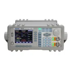
Select “Measure Freq” option by the corresponding soft key. The instrument can measure the frequency of
external signal. The measured result is displayed in the purple text on the upper-left of the TFT display. During
the measurement, the measured signal must be continuous. But the measurement process is intermittent. It
samples the signal using the preset gate time as period, calculates the measurement result, and updates the display.
3.12.2 Set the Gate Time
Select “Gate Time” option. The gate time changes to yellow. Input a new gate time data here by numeric keypad
or rotary dial. Press the key corresponding to the time units to confirm the new data input. The instrument usually
adopts average periodical measurement. The longer gate time is, the more cycle numbers to be collected from the
testing signal, the more stable the average value will be, the more valid digits to get in testing results, but the
slower tracking to the frequency variation will be. The shorter gate time is, the less valid digits to get in testing
results, the faster tracking to the frequency variation will be, which is suitable to frequency testing requiring a
short time of stability.
3.12.3 Low-pass Filter
In the measurement of the external signal, if the signal frequency is relatively low and has high frequency noise,
the measured data has bigger error and is not stable. The low-pass filter is default as OFF. Select “LPF On” option
by the corresponding soft key. This adds a 100 kHz low-pass filter to the input signal. The low-pass filter filters
out the high-frequency noise and makes the measured result much more accurate. If the frequency of the testing
signal is relatively high, the low-pass filter may attenuate the signal, decrease the sensitivity of the measurement,
and even result in the wrong testing data. In this situation, Press the key corresponding to “LPF On” once more to
select the “LPF Off” function to remove the 100 kHz low-pass filter. For the low frequency of square signal,
because of steep edge of the signal, the trigger error is not significant. Therefore, the low pass filter is not
necessary here.
3.13 System Setup
Press key [SYS] and select “System” option. The system interface is displayed. Users can select operations of
store and recall system setup parameters, set up remote control interfaces. This operation is valid only on software
operation via PC, but not valid for rotary dial operations.
3.13.1 Store Parameters
Select “Store” option by the corresponding soft key to store preset parameters into memory of the instrument. The
instrument provides 40 index numbers (0-39) for the parameter memories, starting from index number 0 to 39.
Memories of index number 1~39 are available for user defined setting storage, except memory of number 0.
Memory index number 0 is for the storage of default parameters setup.
3.13.2 Recall Parameters
Select “Recall” by the corresponding soft key. Input recall index number 0 to 39 to recall the stored settings in
each memory. Input number 0 recalls the default parameter setting of the instrument. After the parameters are
recalled, the instrument outputs the signal based on the recalled parameters. In some applications, it is required to
frequently use a set of certain parameters, such as frequency, amplitude, offset, waveform, etc. It is very easy and
- 23 -
Loading ...
Loading ...
Loading ...
