Loading ...
Loading ...
Loading ...

and converted into an analog voltage through D/A converter and amplifier circuitry. Because the waveform data
are the interval samples, the output of DDS is a stepwise sine wave. Thus, the output waveform from DDS has to
be filtered out the high harmonic components by a low-pass filter. The high accurate reference regulator in D/A
converter assures the amplitude precision and stability of the output waveform.
The amplitude controller is a D/A converter. According to the preset amplitude value, this converter generates a
corresponding analog voltage which multiplies with the output signal and produces a final output signal whose
amplitude is equal to the preset value. The offset controller is also a D/A converter. According to the preset offset
value, this converter generates a corresponding analog voltage which adds with the output signal and produces a
final output signal whose offset is equal to the preset value. The output signal is output at the channel A.
2.3 Principle of Operation and Control
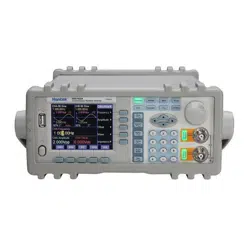
The MCU controls keypad and TFT display through the interface circuitry. When the key is pressed, the MCU
detects the action, finds the code of key, and executes the corresponding program. The TFT display circuit adopts
menu characters to display the working status and parameters of the instrument.
The knob on the front panel can be used to adjust the numeric digit on the cursor position. Every 15-degree
rotation will generate a trigger pulse. Based on the pulse, the MCU can determine the knob left-rotation or
right-rotation. If the rotation is left, the digit on the cursor is subtracted by one. If the rotation is right, the digit is
added by one.
- 9 -
Loading ...
Loading ...
Loading ...
