Loading ...
Loading ...
Loading ...

3.9 Frequency Shift Keying (FSK)
In the digital communication and remote measurement systems, the transmission of the digital signal uses the
Frequency Shift Keying (FSK) or Phase Shift Keying (PSK) method to encode the frequency or phase of the
carrier signal. At the receiving station, the received signal is decoded and recovered to the original digital signal.
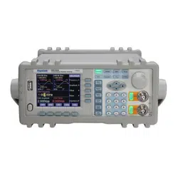
Press key [SK] to select “CHA FSK” option. The function generator outputs the FSK signal on the CHA Output.
The upper-left portion of the TFT displays the FSK waveform. The frequency of the output signal is the
alternative variation of the carrier frequency and the hop frequency. The interval time of alternation is adjustable.
3.9.1 Set the Carrier Frequency
Select “Carrier Freq” option by the corresponding soft key. The carrier frequency value changes to yellow. Input a
new carrier frequency here by numeric keypad or rotary dial. Press the key corresponding to the frequency units to
confirm the new data input. In the FSK mode, the signal of the channel A is the carrier signal. The carrier
frequency is the first frequency value of channel A.
3.9.2 Set the Hop Frequency
Select “Hop Freq” option by the corresponding soft key. The hop frequency value changes to yellow. Input a new
hop frequency here by numeric keypad or rotary dial. Press the key corresponding to the frequency units to
confirm the new data input. The hop frequency is the second frequency value of the channel A.
3.9.3 Set the Interval Time
Select “Interval” option by the corresponding soft key. The interval time value changes to yellow. Input a new
interval time data here by numeric keypad or rotary dial. Press the key corresponding to the time units to confirm
the new data input.
3.10 Amplitude Shift Keying (ASK)
Press key [SK] to select “CHA ASK” option. The function generator outputs the ASK signal on the CHA Output.
The upper-left portion of the TFT displays the ASK waveform. The amplitude of output signal is the alternative
variation of the carrier amplitude and the hop amplitude. The interval time of alternation is adjustable.
3.10.1 Set the Carrier Amplitude
Select “Carrier Amp” option by the corresponding soft key. The carrier amplitude value changes to yellow. Input
a new carrier amplitude data here by numeric keypad or rotary dial. Press the key corresponding to the amplitude
units to confirm the new data input. In the ASK mode, the channel A signal is the carrier signal. The carrier
amplitude is the first amplitude value of channel A signal.
3.10.2 Set the Hop Amplitude
Select “Hop Amp” option by the corresponding soft key. The hop amplitude value changes to yellow. Input a new
hop amplitude data here by numeric keypad or rotary dial. Press the key corresponding to the amplitude units to
confirm the new data input. The hop amplitude is the second amplitude value of the channel A signal.
- 21 -
Loading ...
Loading ...
Loading ...