Loading ...
Loading ...
Loading ...
6
2.2 MaxiVCI V200 — Vehicle Communication
Interface
2.2.1 Product Overview
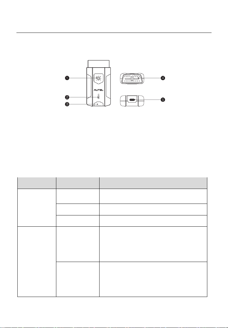
Figure 2-3 MaxiVCI V200 Views
1. Flashlight Button
2. Power LED
3. Vehicle/Connection LED
4. Vehicle Data Connector (16-pin)
5. USB Port
Table 2-1 VCI LED Description
LED
Color
Description
Power LED
Yellow
The VCI is powered on and performing
self-check.
Green
The VCI is ready for use.
Flashing Red
The firmware is upgrading.
Vehicle/
Connection
LED
Green
Solid Green: The VCI is connected via
USB cable.
Flashing Green: The VCI is
communicating via USB cable.
Blue
Solid Blue: The VCI is connected via
Bluetooth.
Flashing Blue: The VCI is
communicating via Bluetooth.
Loading ...
Loading ...
Loading ...