Loading ...
Loading ...
Loading ...
8
English
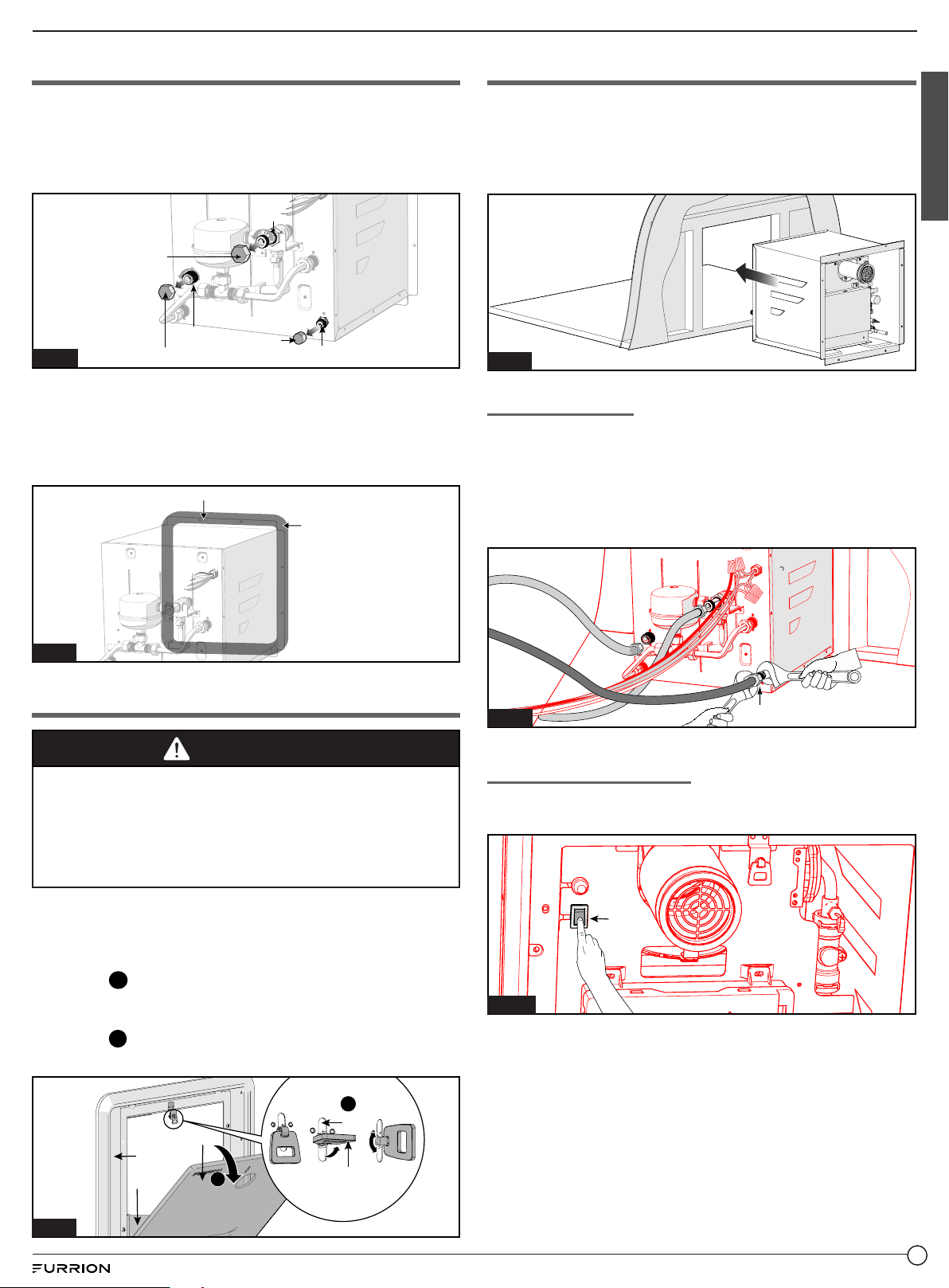
Prepare Water Heater
1. Take the water heater out of its packaging by grasping
the metal sides of the housing and lifting upward until fully
removed from the box.
2. Remove protective caps for COLD (blue), HOT (red) water
connector and GAS connector from back side. (Fig. 13)
Fig. 13
Cover Cap (Red)
Cover Cap (Blue)
HOT
Cover Cap (Black)
COLD
GAS
3. A
pply adequate water sealing material, e.g. butyl tape
(recommended width: 1”, not provided), around the entire
backside flange area and holes.
(Fig. 14)
NOTE: Do not use adhesive sealing material e.g. silicone
for the watertight seal.
Fig. 14
Continuous bead
around corners
Butyl Tape
Prepare Water Heater Door
WARNING
Suffocation and/or Fire Hazard
● Use only the door kit assembly specified for this
product, other types may restrict combustion air and
exhaust gases
Failure to follow instruction could lead to serious injury,
property damage or death.
● The door of the Furrion water heater is fixed to the
mounting flange by a latch.
● Remove the access door and frame from the box,
separate the components. (Fig. 15)
− Step
1
: separate the access door from the mounting
frame. Lift the latch and rotate 90° to unlock the door
cover from the trim.
− Step
2
: Pull the access door from the mounting frame.
NOTE: The baffle does not need to be removed.
1
2
Slot
Door Latch
Access Door
Door Cover
Baffle
Fig. 15
Water Heater Installation
1. Position the water heater carefully into the frame opening ,
evenly space the flange to the exterior wall of the RV. (Fig. 16)
NOTE: Ensure area beneath and behind the appliance is
clean without debris and obstruction. Carefully slide the
appliance across the floor to prevent linoleum damage.
Fig. 16
Gas Connection
1. Connect the gas service line
to the ⅜” LP gas flared fitting
on the back of the appliance. Use two wrenches to tighten
the compression fitting. Avoid dama
ging the unit by over-
tightening. (Fig. 17)
NOTE: Do not use sealing tape or compound on the
compression type fitting.
GAS
Fig. 17
Electrical Connection
1. Set the power switch (Fig. 18) in front of the water heater
to the “OFF” position.
Power
Switch
Fig. 18
Loading ...
Loading ...
Loading ...