Loading ...
Loading ...
Loading ...
7
English
● A non Metallic Flexible gas hose must be rated for 149
o
F
(65
o
C). Anchor appropriately to prevent fatigue and failure
from wear edges.
● Make sure that the operating pressure of the gas supply
corresponds to the operating pressure of the appliance
11~14in-wc (27.4~34.9mbar).
1. Locate entry point for the plumbing to service the
rear of the appliance. Ensure entry point is not in the
footprint space of the appliance. (Fig. 2)
2. Feed gas line into proximity, leave enough length to
flex into position so that when connected no kinks are
created.
NOTE: An approved semi-flexible metallic pipe is
acceptable to connect as an extension from the gas
line to the appliance.
3. Terminate gas line with fittings to connect to the
appliance.
Electrical Wiring
WARNING
Electrical Shock Hazard
● Disconnect all power before performing any work.
● Always use a certified and proven 12V isolated power
supply, that is properly grounded to the RV.
● Follow all applicable codes, regulations and instruction
material when performing service work.
Failure to follow instruction could result in serious injury or
death.
● Wiring connected to or in proximity of the appliance must
be rated for 140°F (60°C) minimum.
● Use only insulated terminals for all electrical connections.
● The appliance requires a power source that can
adequately provide 10~17V DC to function properly.
Contact furrion for available Power centers, converters
and distribution panels.
1. Select a distribution branch greater than 3A, preferably
15 amp, to provide nominal 12V to the appliance from the
distribution panel.
NOTE: The appliance has a built in 10A fuse, serviceable
from the front of the product. The appliance can be on
a dedicated or shared branch circuit with the same or
higher rating.
Optional: A power switch can be placed in the living
quarters for convenience, but not required as a switch is
located externally on the appliance. If the switch is fused,
make sure it is rated for at least 3amps. See Fig. 10 for
reference.
2. Locate entry point for the wiring to service the rear of
the appliance. Ensure entry point is not in the footprint
space of the appliance (Fig. 2) Make sure any edges are
protected to prevent wire abrasion from occurring.
3. Determine the appropriate wire gauge (AWG) for the 12V
power supply length. Ensure enough wire is available to
make adequate connection.
− 16AWG max. 40 feet (12m)
− 14AWG max. 66 feet (20m)
4. Feed wire from power source to the entry point. Make
connection to the power source.
Water Plumbing
● The plumbing must be rated to supply between 35-70PSI
nominal.
● Connections can be made using PEX swivel nut adapters
with NPT straight threads and a cone seal or with a
standard ½” FPT fittings.
● For proper operation this water heater requires a minimum
water flow of 0.32 Gallon per Minute (gpm).
1. Locate entry point for the plumbing to service the
rear of the appliance. Ensure entry point is not in the
footprint space of the appliance. (Fig. 2)
2. Create a piping layout to supply the appliance and all
faucets, reference Fig. 11.
NOTE: Dry fit tubing and fittings before clamping
together. Adjust sections to avoid excessive stress on
the fittings when assembled to the appliance. It may be
helpful to fit the appliance into position to determine the
appropriate piping layout.
3. Clamp and seal all fittings together. Terminate piping
with the appropriate fittings.
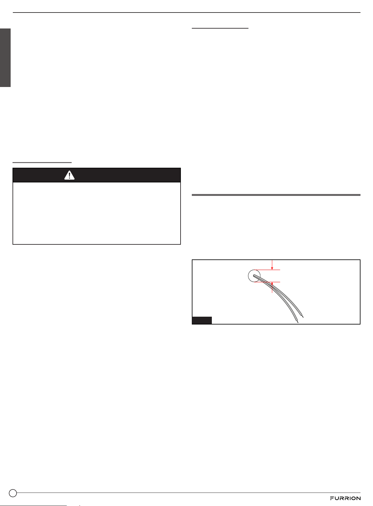
Prepare Wall Control
1. Determine a location to install the wall controller inside the
RV.
2. Drill a ¾" hole and clean edges.
3. If necessary, run two electrical wires that extend the
wall control connections (blue wires) to the appliance
connections (blue wires) using the appropriate wire size.
(Fig. 12)
− 16AWG max. 65ft (20m).
¾”
Fig. 12
Loading ...
Loading ...
Loading ...