Loading ...
Loading ...
Loading ...
9
English
2. Connect the power supply wires (on rear of water heater
- white and black wire) to the appropriate nominal 12V DC
power source connection. (Fig. 19)
NOTE: The black wire is positive (+) and the white wire is
negative (-).
3. Connect the wall controller wires (2 blue wires on the
appliance). (Fig. 19)
NOTE: Polarity does not matter, the wires can be
connected to either blue wires.
12V DC
Power
Supply
Wall
Controller
12V
White: -12V
Not Provided
Black: +12V
Blue
Fig. 19
Water Connection
1. Connect both HOT and COLD water lines to the appropriate
½”NPT fittings. (Fig. 20)
NOTE:
− DO NOT over tighten connection fittings.
− For new installations, it is advisable to flush the water
system of debris before connecting to the appliance.
Fig. 20
COLD
HOT
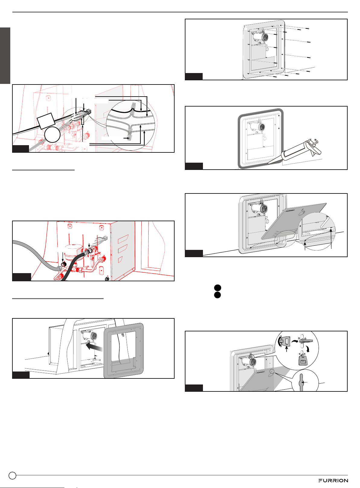
Securing the Water Heater
1. Insert the door flange into the water heater housing and
press the flange firmly against the sidewall. (Fig. 21)
Fig. 21
2. Secure the flange to the vehicle using 12 - #8 (min 1") pan
head screws (not provided) through each hole along the
perimeter. Verify that a tight seal exists between the side
wall and the flange. (Fig. 22)
NOTE: Ensure the butyl tape completes a tight seal
between the RV siding and appliance flange. If gaps exist,
remove the appliance and apply a double layer of butyl
tape.
Fig. 22
3. Apply a liberal amount of sealant around the door frame
to fill any gaps to the RV wall. (Fig. 23) Wipe any excess
sealant.
Fig. 23
4. Insert the door into the pins at the bottom of the water
heater. (Fig. 24)
Hole
Pin
Fig. 24
5. Align the latch on the flange with the slot on the door, then
push the door and rotate the latch to lock the door into
place. (Fig. 25)
− Step
1
: Pull and rotate the lever 90° to lock the latch.
− Step
2
: Turn down the folding latch to lock.
NOTE: Damage to the assembly door and the RV if the
assembly door is not closed properly! Make sure that
the assembly door is flush with the cover plate when
closed.
Fig. 25
Door Latch
Slot
Loading ...
Loading ...
Loading ...