Loading ...
Loading ...
Loading ...
17
English
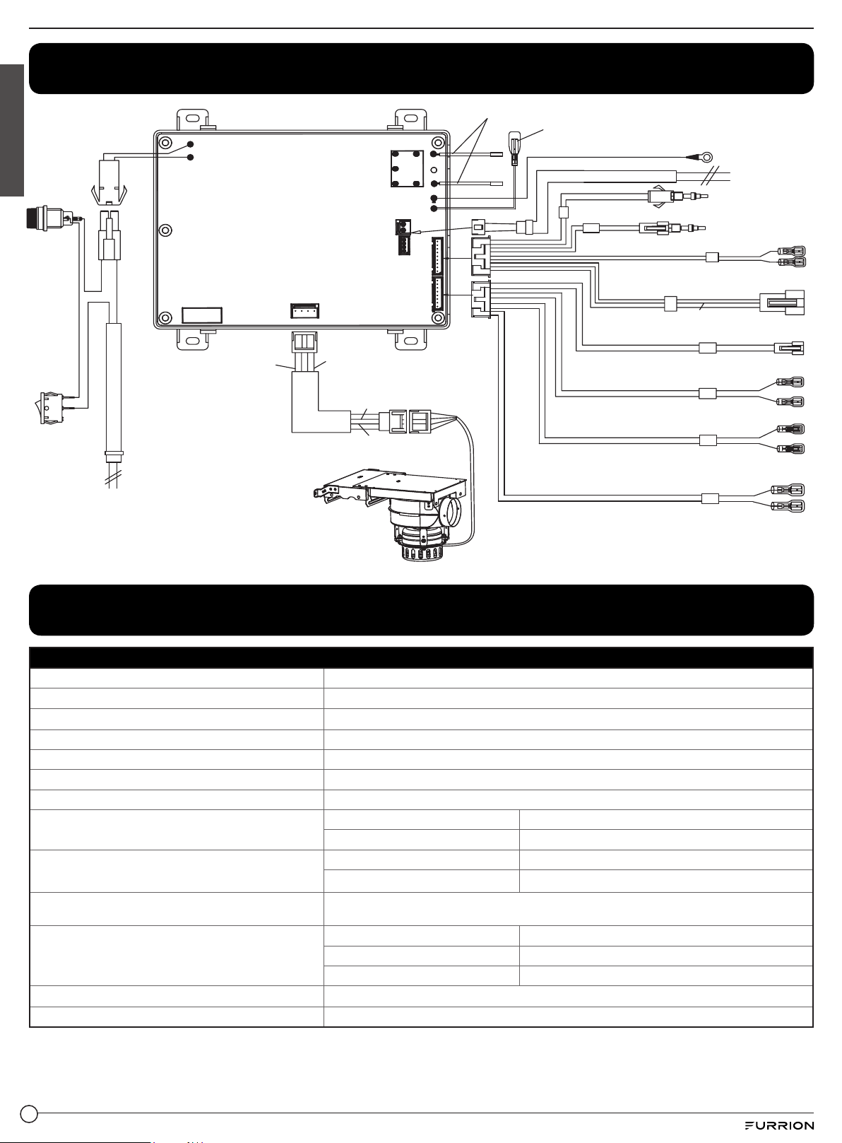
Wiring Diagram
Fuse
To Ignition pin
Blue
Blue
To proportional valve
White
Black
Black
Black
Brown
Red
Red
To water
flow sensor
Brown
Blue
To switch on/off
proportional valve
Black
Yellow
Yellow
Yellow
Yellow
Outlet temp probe
Inlet temp probe
To wind pressure switch
White
White
0~5V DC (Brown)
Feed back (White)
Ground (Black)
+24V (Red)
Power 12VDC
-White+Black
Black
Black
White
Black
Black
+12VDC
-12VDC
To Flame sensor
To Remote
White
To Ground
Black
To ECO thermostat
White
Subsection valve line
Specifications
Specifications
BTU/HR
60,000 BTU
Fuel
Propane (LP Gas)
Inlet Pressure
11” WCI Min to 14” WCI Max
Manifold Pressure
0.96”-7.6” WCI
Power Input
12V DC < 3 Amp
Water Operating Pressure
7.2 PSI-65 PSI
Orifice (mm)
Ø 1.1
Altitudes: 0-2000ft (0~610m)
Manifold Pressure (Pa)
1920
Max Fan Speed
58 r/s
Altitudes: 2000-4500ft (610-1370m)
Manifold Pressure (Pa)
2360
Max Fan Speed
68 r/s
Product Dimensions (W x H x D)
Body Only (Model: FWH09A)
12⅝” (320mm) x 12⅝” (321mm) x 19⅛” (486.5mm)
Assembly (Body and Door) Dimensions (W x H x D)
Body with Door (FWH09EA-PS) 16/” x 16/” x 19/” (410mm x 410mm x 500.6mm)
Body with Door (FWH41EA-PS) 16/” x 18/” x 19/” (410mm x 460mm x 500.6mm)
Body with Door (FWH46EA-PS) 18/” x 18/” x 19/” (460mm x 460mm x 500.6mm)
Shipping Weight
31 lbs.
Setting Temperature Range
95
o
F (35
o
C) ~ 124
o
F (51
o
C)
Loading ...
Loading ...
Loading ...