Loading ...
Loading ...
Loading ...
Thump12BST • Thump15BST Powered Loudspeakers
10
Thump12BST • Thump15BST Powered Loudspeakers
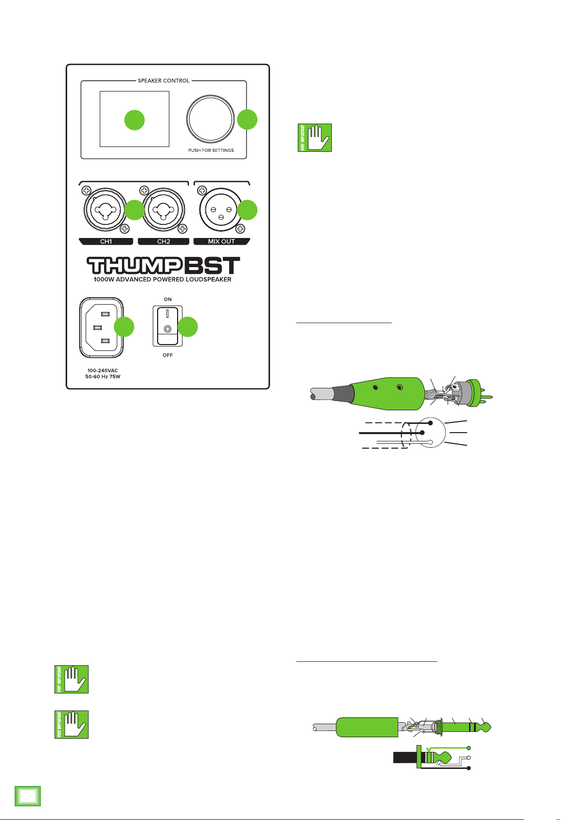
Thump12BST / Thump15BST Loudspeakers: Rear Panel Features
Thump Connect App
ThumpBST loudspeakers are designed to be used in
conjunction with the Thump Connect App. With it, all of
the hardware features listed here – and more! – may be
controlled remotely via Bluetooth connection. The only
thing the Thump Connect App can’t do is turn the unit
on and off.
More information about the Thump Connect App may
be found by visiting the Thump Connect App Reference
Guide.
1. Power Connection
This is a standard 3-prong IEC power connector.
Connect the detachable power cord (included in
the packaging with the loudspeaker) to the power
receptacle, and plug the other end of the power
cord into an AC outlet.
Make sure that the AC power is matched to
the AC power indicated on the rear panel
(below the IEC receptacle).
Disconnecting the plug’s ground pin is
dangerous. Don’t do it!
2. Power Switch
Press the top of this rocker switch inwards to turn on
the loudspeaker. Press the bottom of this rocker switch
inwards to turn off the loudspeaker.
As a general guide, the mixer (or other
signal source) should be turned on first,
subwoofers next, and loudspeakers last.
As such, the loudspeakers should also be turned
off first, followed by the subwoofers, then the mixer.
This will reduce the possibility of any turn-on or
turn-off thumps and other noises generated by any
upstream equipment from coming out of the speakers.
3. XLR and 1/4" Combo Inputs
Both input channels may accept a balanced
mic signal using an XLR connector. They are wired
as follows, according to standards specified by the
AES (Audio Engineering Society).
XLR Balanced Wiring:
Pin 1 = Shield (ground)
Pin 2 = Positive (+ or hot)
Pin 3 = Negative (– or cold)
In addition to accepting a balanced mic signal using
an XLR connector, these input channels may also accept
1/4" line-level signals driven by balanced or unbalanced
sources.
Additionally, both input channels may accept Hi-Z
sources (such as guitars) via the 1/4" input without
the need for a separate DI box.
To connect balanced lines to these inputs, use
a 1/4" Tip-Ring-Sleeve (TRS) plug. “TRS” stands for
Tip-Ring-Sleeve, the three connection points available
on a stereo 1/4" or balanced phone jack or plug. TRS
jacks and plugs are used for balanced signals and are
wired as follows:
1/4" TRS Balanced Mono Wiring:
Sleeve = Shield
Tip = Hot (+)
Ring = Cold (–)
2
3
1
SHIELD
COLD
HOT
SHIELD
COLD
HOT
3
2
1
SLEEVE
TIP
SLEEVE
TIP
RING
RING
TIP
SLEEVERING
1
3
5
4
6
2
Loading ...
Loading ...
Loading ...