Loading ...
Loading ...
Loading ...
ASSEMBLY iNSTRUCTIONS
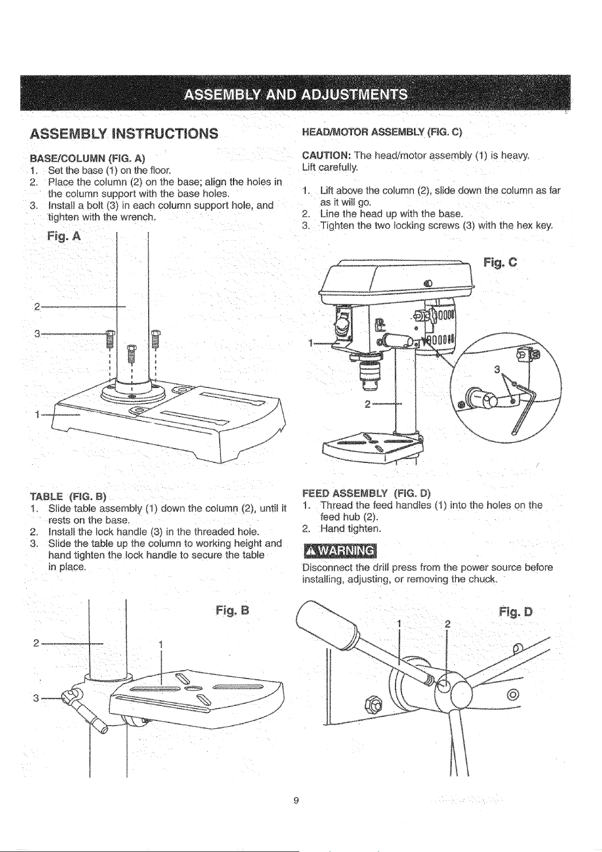
BASFJCOLUMN (FIG. A)
1. Set the base (1) on the floor.
2. Place the column _2_on the base: align the hoEes in
the column support with the base ho}es,
3. install a boll _3} in each column support hole, and
lighten with the wrench.
Fig, A
HEAD,z&_OTORASSE_,eBLY (FIG, C)
CAUTION: The head/motor assembly (1) is heavy,
1. Lift above the column (2), s}ide down the column as far
as it witl go.
2. Line the head up with the baser
3. Tighten the two Iocking screws [3) w_th the hex key,
F_g- C
2_
3
-- 4
/
TABLE (RG. B)
1. SHde table assembly (1) down the column (2), unti_ it
rests on the base.
2 _nstaH1he lock handle (3) in the threaded he{e.
3 Stide the table up the column to working height and
hand tignten the lock handle to secure _heteble
in p_aceo
FEED ASSEMBLY {RGo D)
1. Thread the feed handles It ) ir [o the ho_es on [_qe
feed hub (2),
2. Hand tighten,
Disconnect the drill 3ress from the power source before
installing adiusting, or remov|ng [he chuck
_J
_/
Loading ...
Loading ...
Loading ...