Loading ...
Loading ...
Loading ...
ADJUSTMENTS
NOTE: All necessary adjustments for the proper functioning
of your drHJpress nave been made at the factory, Phase
do net modify them. However. because of normal wear
and tear on your tool, some readjustments may be
necessary,
Always unp{ug your tool from the Power source before
any adjustment°
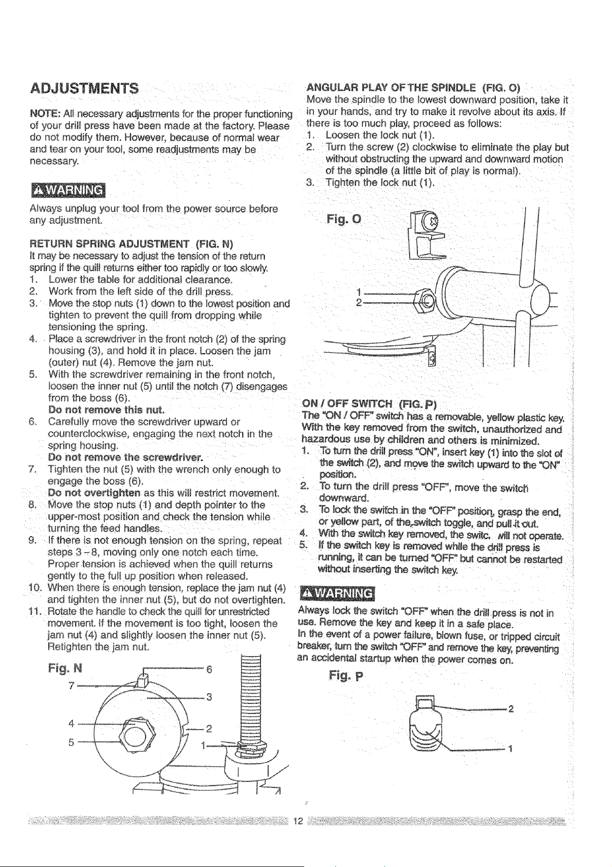
RETURN SPRING ADJUSTMENT {FIG. N)
It may _ necessary to adjust the tension of the re[urn
spdng if the quill returns either too rapidly or too slowly,
1. Lower the tabb for additional ciearanceo
2. Work from the teft side of the drill press,
3. Move the stop nuts (1) 4own to the k)west position and
tighten to prevent the quill from dropping wh{le
tensioning the spring_
4. Place a screwdriver in the front notch (2) of the spring
housing (3), and hold it in place. Loosen the jam
(outer) nut (4) Remove the/am nuL
5. With the screwdriver remaining in the front notch
bosen the inner nut (5) until the notch (7) disengages
from the boss (6}.
Do not remove this nut,
6 Carefully move the screwdriver upward or
coume rclockwise engaging the next notch in the
Do nol_ remove the screwdriver°
7 Tighten the nut (5) with the wrench only enough to
engage the boss (6).
D_ net ove_lghten as this Will restrict movement.
8. Mo_ the stop nuts (;1) and depth pointer to the
upper-most position and check the tension whi_e
turning the feed handles.
9. _fthere is not enough tension on the spring, repeat
steps 3-& moving only one notch each time.
Proper tension is achieved when the auiH returns
gent_y to the fun up position when released.
10. When _nere _senough tension, replace the jam nut (4)
and tighten the inner nut (5) but do not overtighten
11 Rotate the handle to check the auil_for unrestricted
movement. If the movement is too tight, _oosen the
iam nut (4) and slightly _oosen the inner nu[ (5_,
Reti_hten the _am nut.
Figo N
\
ANGULAR PLAY OFTNE SPINDLE (FIG. O}
Move the spindle to the bwest downward position, take it
in your hands, and try to make it revolve about its axis. If
there is too much p}a_; proceed as follows:
1 Loosen the lock nut (1),
2. Turn the screw (2} cfockwise to eliminate the play but
without obstructing the upward and downward motion
of the spindle (a little bit of play is normat),
3. Tighten the lock nut (1).
ON / OFF SWITCH (F_G. p}
The _N / OFF _t_:_ _s a remorse, yellow plastic key.
With _e key removed from the sw_tch, unauthorized and
hazardous use by children and othe_ is minimized,
1 To turn _e drill pre_ _ON", insert key (1) into the slot of
the S_ r(2), and rnqve the switch upward to the _N"
2, To turn the drill press "OFF* move the switch
dOWnward°
3o To loc_ the _ch in the °OFF posit_orb _sp #_e end.
or yellow part, of toggle, and #ullA_ut.
4. _%':_ththe sw_tchkey re_, _ switc, z,_lir_t operate°
& _ the s_ch key is rem_ while the _lt press is
_nning, _ can _ turned "OFF" but cannot be restarted
w_out i_se_ng the _#ch key
Nways lock the switch "OFF_ when the ddll press is not in
use, Remove the key and keep it in a safe place.
in the event of a power failure, Mown fuse, or tripped circuit
breaker, turn the s_i_ch _FF" ar_ _rnove th_ k_; _eventing
an accidenta! startup when the power comes one
Fbo P
12
Loading ...
Loading ...
Loading ...