Loading ...
Loading ...
Loading ...
25
W415-1345 / C / 02.14.17
EN
The vent system must be supported approximately every 3 feet (0.9m) for both vertical and horizontal runs.
Use Wolf Steel Ltd. support ring assembly or equivalent noncombustible strapping to maintain the minimum
clearance to combustibles for both vertical and horizontal runs.
A
ll inner exhaust and outer intake vent pipe joints may be sealed using either red high temperature
silicone sealant (W573-0002) (not supplied) or black high temperature sealant W573-0007 Mill Pac (not
supplied) with the exception of the appliance exhaust fl ue collar which must be sealed using Mill Pac.
25.1A
A
. Move the appliance into position. Measure the
vent length required between terminal and
appliance taking into account the additional
length needed for the fi nished wall surface
and any 1¼” (31.8mm) overlaps between
venting components.
B. Apply high temperature sealant W573-0007 Mill Pac
(not supplied) to the outer edge of the inner exhaust
fl ue collar of the appliance. Attach the fi rst inner
rigid pipe component and secure using a minimum of
3 self tapping screws. Repeat using the outer rigid pipe.
C. Insert the vent pipes through the fi restop maintaining the required clearance to combustibles. Holding
the air terminal (lettering in an upright, readable position), secure to the exterior wall and make
weather tight by sealing with caulking (not supplied).
The air terminal mounting plate may be recessed into the exterior wall or siding no greater than the
depth of the return fl ange.
26.1A
SCREWS
#10x2"
OUTER
RIGID
PIPE
CAULKING
INNER
RIGID
PIPE
SCREWS
SELF DRILLING
#8x1/2"
1" (25.4mm)
OVERLAP
SEALANT
HI-TEMP
5.4.3 APPLIANCE VENT CONNECTION
A
. Install the inner exhaust fl ue collar to the appliance. Secure
with a minimum of 3 #8 screws. Seal the joint and screw
holes using Mill Pac sealant (W573-0007) (not supplied).
B. Install the outer fl ex pipe to the appliance. Attach and seal
the joints using a red RTV silicone and a minimum of 3 #8
screws.
28.1D
2” (50.8mm)
OVERLAP
HIGH TEMP
SEALANT
#8 X 1/2”
SELF
DRILLING
SCREWS
A 45° corner installation can have 0” (0mm) rise between the appliance
combustion air collar and the air terminal. In this case, vent lengths must be
kept to a maximum of 24” (60.9cm) . For longer vent lengths, a minimum
vertical rise of 24” (60.9cm) is required.
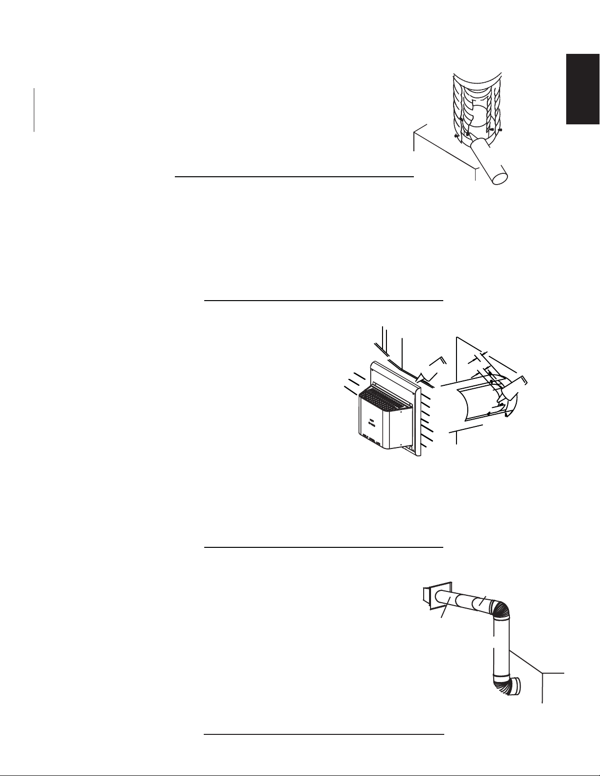
A. Follow the instructions for "HORIZONTAL AIR TERMINAL
INSTALLATION" section.
B. Continue adding components alternating inner and outer vent pipes. Ensure that
all inner vent pipes and elbows have sufficient vent spacers attached and each
component is securely fastened to the one prior. Attach the telescopic sleeve to the
vent run. Secure and seal. To facilitate completion, attach inner and outer couplers to
the air terminal.
C. Install the air terminal. See “HORIZONTAL AIR TERMINAL INSTALLATION” section. Extend the outer
telescopic sleeve; connect to the air terminal assembly. Fasten with screws and seal.
TELESCOPIC SLEEVE
VENTING
AIR TERMINAL
20" (508mm)
COUPLER
48.2A
5.5 USING RIGID VENT COMPONENTS
5.5.1 HORIZONTAL AIR TERMINAL INSTALLATION
5.5.2 EXTENDED HORIZONTAL AND CORNER TERMINAL INSTALLATION
Loading ...
Loading ...
Loading ...