
Loading ...
Loading ...
Loading ...
24
W415-1345 / C / 02.14.17
EN
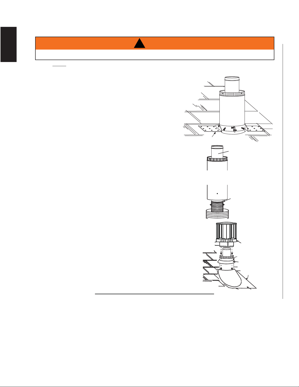
5.4.2 VERTICAL AIR TERMINAL INSTALLATION
A
. Fasten the roof support to the roof using 6 screws. The roof support is optional. In this case the
venting is to be adequately supported using either an alternate
method suitable to the authority having jurisdiction or the optional
roof support.
B. Stretch the inner fl ex pipe to the required length. Slip the inner
fl ex pipe a minimum of 2” (51mm) over the inner pipe of the
air terminal connector and secure with a minimum of
3 screws. Seal using a heavy bead of Mill Pac sealant
(W573-0007) (not supplied).
C. Repeat using the outer fl ex pipe, using a heavy bead of red
RTV silicone (W573-0002) (not supplied) and a minimum of
3 screws.
D. Thread the air terminal connector / vent pipe assembly
down through the roof. The air terminal must be positioned vertically
and plumb. Attach the air terminal connector to the roof support,
ensuring that the top of the air terminal is 16” (40.6cm) above the
highest point that it penetrates the roof.
E. Remove nails from the shingles, above and to the sides of the air
terminal connector. Place the fl ashing over the air terminal connector
leaving a min. 3/4” (19mm) of the air terminal connector showing
above the top of the fl ashing. Slide the fl ashing underneath the
sides and upper edge of the shingles. Ensure that the air terminal
connector is properly centered within the fl ashing, giving a 3/4”
(19mm) margin all around. Fasten to the roof. Do not nail through
the lower portion of the fl ashing. Make weather-tight by sealing with
caulking. Where possible, cover the sides and top edges of the
fl ashing with roofi ng material.
F. Aligning the seams of the terminal and air terminal connector,
place the terminal over the air terminal connector making sure
the vent pipe goes into the hole in the terminal. Secure with 3
screws.
G. Apply a heavy bead of weatherproof caulking 2” (51mm)
above the fl ashing. Install the storm collar around the air
terminal and slide down to the caulking. Tighten to ensure that
a weather-tight seal between the air terminal and the collar is
achieved.
H. If more vent pipe needs to be used to reach the appliance see
“HORIZONTAL AIR TERMINAL INSTALLATION” section.
24.1D
STORM COLLAR
FLASHING
CAULKING
WEATHER
SEALANT
2” (51mm)
AIR INLET
BASE
ROOF SUPPORT
INNER FLEX PIPE
INNER PIPE
MILL PAC
SEALANT
(W572-0007)
AIR
TERMINAL
CONNECTOR
OUTER FLEX PIPE
MAINTAIN A MINIMUM 2” (51mm) SPACE BETWEEN THE AIR INLET BASE AND THE STORM COLLAR.
!
WARNING
NOTE : Fastening hardware provided with appropriate roof terminal and liner kits.
Loading ...
Loading ...
Loading ...