
Loading ...
Loading ...
Loading ...
14
W415-1345 / C / 02.14.17
EN
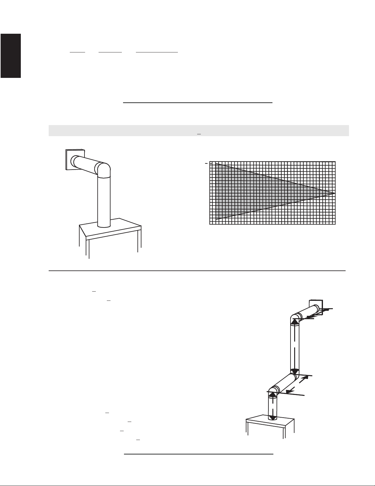
3.7 ELBOW VENT LENGTH VALUES
15.1A
FEET INCHES MILLIMETERS
1° 0.03 0.5 12.7
15° 0.45 6.0 152.4
30° 0.9 11.0 279.4
45° 1.35 16.0 406.4
90°* 2.7 32.0 812.8
* The fi rst 90° offset has a zero value and is shown in the formula as - 90°
16.1B
Simple venting confi guration (only one 90° elbow)
(H
T
) < (V
T
)
For vent confi gurations requiring more than one 90° elbow, the following formulas apply:
Formula 1: H
T
< V
T
Formula 2: H
T
+ V
T
< 40 feet (12.2m)
Example:
V
1
= 3 FT (0.9m)
V
2
= 8 FT (2.4m)
V
T
= V
1
+ V
2
= 3 FT (0.9m ) + 8 FT (2.4m) = 11 FT (3.4m)
H
1
= 2.5 FT (0.8m)
H
2
= 2 FT (0.6m)
H
R
= H
1
+ H
2
= 2.5 FT (0.8m) + 2 FT (0.6m) = 4.5 FT (1.4m)
H
O
= .03 (three 90° elbows - 90°) = .03 (270° - 90°) = 5.4 FT (1.7m)
H
T
= H
R
+ H
O
= 4.5 FT (1.4m) + 5.4 FT (1.6m) = 9.9 FT (3m)
H
T
+ V
T
= 9.9 FT (3m) + 11 FT (3.4m) = 20.9 FT (6.4m)
Formula 1: H
T
< V
T
9.9 FT (3m) < 11 FT (3.4m)
Formula 2: H
T
+ V
T
< 40 FT (12.2m)
20.9 FT (6.4m) < 40 FT (12.2m)
Since both formulas are met, this vent confi guration is acceptable.
See graph to determine the required vertical
rise V
T
for the required horizontal run H
T
.
The shaded area within the lines represents
acceptable values for H
T
and V
T
0
2.5
(0.8)
5
(1.5)
7.5
(2.3)
10
(3.1)
12.5
(3.8)
15
(4.6)
40 (12.2)
10 (3.1)
20 (6.1)
30 (9.1)
17.5
(5.3)
20
(6.1)
39 (11.9)
REQUIRED
VERTICAL
RISE IN FEET
(METERS)V
T
HORIZONTAL VENT RUN PLUS OFFSET IN
FEET (METERS) H
T
90°
90°
90°
V
1
V
2
H
1
H
2
3.8 TOP EXIT HORIZONTAL TERMINATION
Loading ...
Loading ...
Loading ...