Loading ...
Loading ...
Loading ...
9
W415-1355 / A / 11.16.16
EN
While the liners must be continuous from the appliance to the chimney cap,
to achieve the needed length, they may be coupled, using an approved
coupler.
We recommend that exhaust vents that pass through unheated spaces,
such as tall exterior chimneys, be wrapped in a protective sleeve to minimize
condensation and reverse fl ow symptoms. See "TROUBLESHOOTING"
section for details.
This appliance is approved for use with a 3" (76mm) exhaust and air intake.
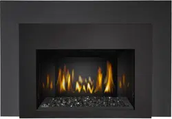
A. OUTSIDE: Slip the one end of a liner a minimum of 2" (51mm)
over the sleeve of the air terminal. Secure using 3 screws. Then seal the joint and screw heads with
high temperature sealant. Repeat with the other liner.
NOTE: We recommend that the other end of the exhaust liner be marked to eliminate the
exhaust liner being connected to
the intake collar at the appliance.
B. Gently stretch the liners to the
required lengths and insert into the
chimney. Trim and fi t the fl ashing
plate to suit the chimney termination.
Place the air terminal onto the top of
the chimney. Make weather tight by
sealing with caulking (not supplied).
Fasten to the chimney with screws
and plugs (not supplied).
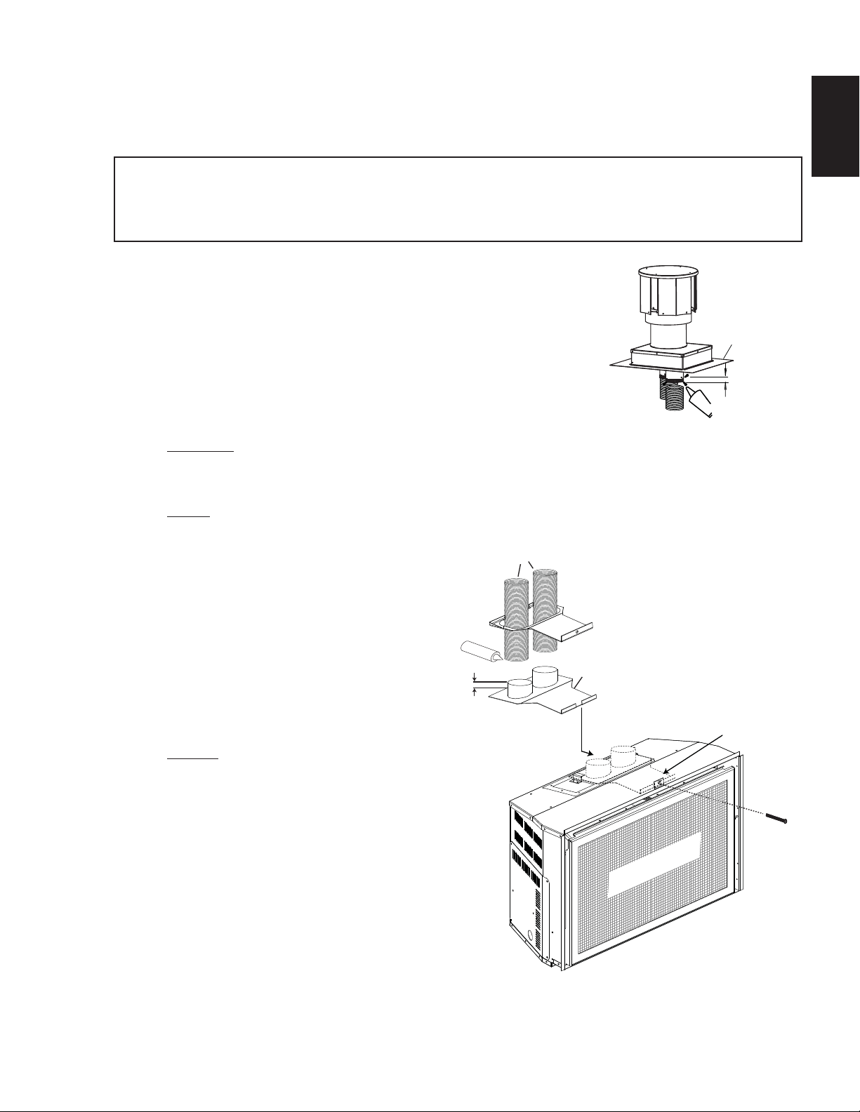
C. INSIDE: Remove the securing screw
from the front of the vent mounting
assembly. Slide the vent mount
assembly from the track. Route the
fl ex liners through the slider. Attach
and secure the liners to the vent
mounting plate, ensuring that the
marked exhaust liner is attached to
the exhaust collar.
D. The appliance may now be pushed
into the opening and the mounting
plate assembly slid back into the
track, and the securing screw started. Once the appliance is in its fi nal position, tighten the securing
screw until the slider makes contact with the front stop.
FLASHING
PLATE
2” (50.8mm)
OVERLAP
MILL-PAC
INTAKE
EXHAUST
SECURING
SCREW
SLIDER
MOUNTING
PLATE
HIGH TEMP
SEALANT
2” (50.8mm)
OVERLAP
3” (76.2mm)
LINERS
EXHAUST
INTAKE
VENT MOUNT
ASSEMBLY
SAFETY BARRIER
3.2 CHIMNEY CONNECTION
Chimney installation must conform to both national and local code requirements. The chimney must be lined
with one 3" (76mm) diameter liner for intake and one 3" (76mm) diameter liner for exhaust. The minimum and
maximum vent lengths are 10 (3m) and 35 (11m) feet respectively. Recommended kits come in 3 lengths:
2-3" (51-76mm) DOUBLE PLY ALUMINUM LINER-INLET AND EXHAUST:
GDI-320KT VENT KIT 20FT
GDI-325KT VENT KIT 25 FT
GDI-335KT VENT KIT 35 FT
Loading ...
Loading ...
Loading ...