A
H I J K L M
B C
D
E F
M1743010 1743011 E V0
Installation Overview
Congratulations, You have Installed the
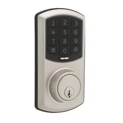
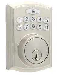
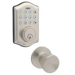
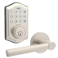
Trubolt Orion Wi-Fi Deadbolt
(1743010 1743011)
Turn Sheet over for Programing Instructions.
8
Install Enclosed Latch and Strike Plate321
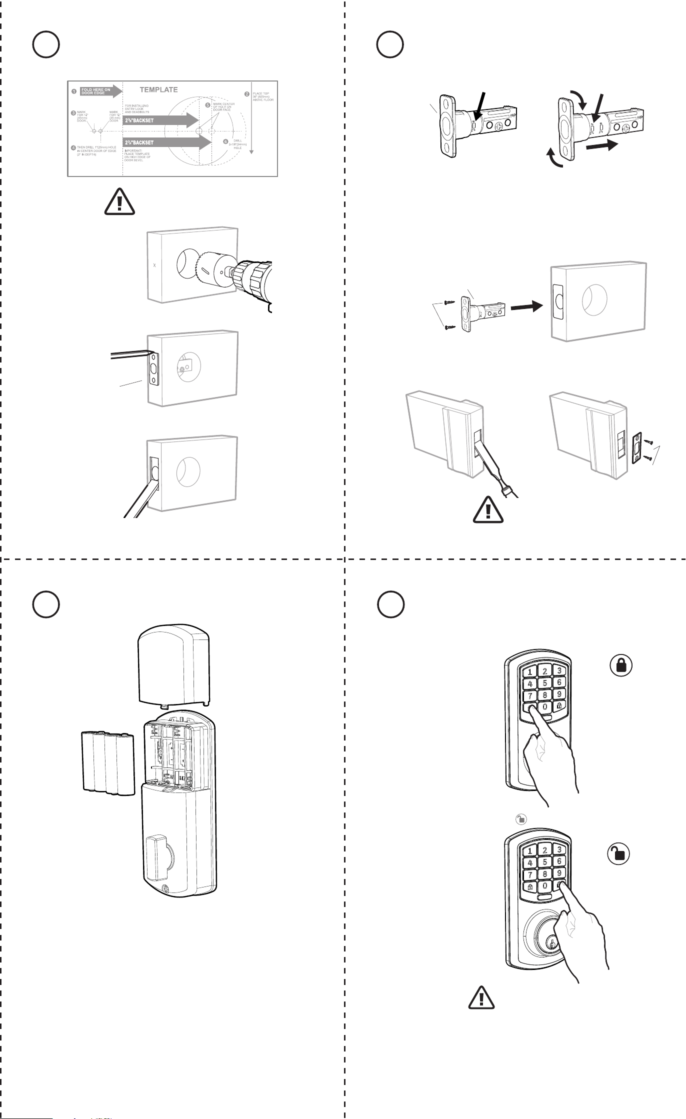
Refer to Template for
Door Prep Instructions
F
NOTE: Skip this step if your door comes with pre-drilled holes.
ENGLISH
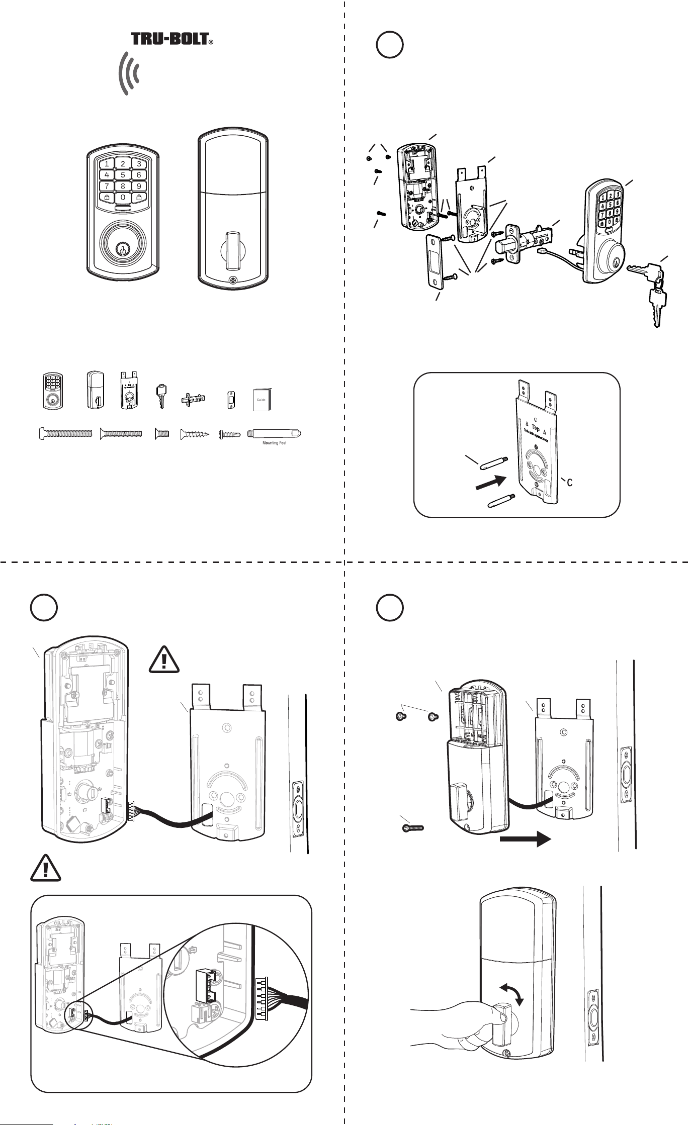
Package Includes:
1 - Exterior Faceplate
1 - Interior Faceplate
1 - User Guide
2 - Keys
1 - Strike Plate
1 - Mounting Plate
1 - Latch
1 - 1 3/8” Screws
2 - 5/16” Screws
2 - 1 “ Screws
4 - 3/4”Screws
1 - Optional Set Screw
Read this manual carefully before installing and operating!
3/4” Screws1” Screws 5/16” Screws1 3/8” Screws
Exterior Faceplate Interior Faceplate
User Guide
Keys
Latch
Model 1743010 1743011
Optional Set Screw
Please carefully check the above list to confirm all items have been received. If any items are
missing, please contact Consumer Assistance. (See page for contact information)
Mounting Plate
Preparing Door
7 Install Batteries and Cover
Strike Plate
C
Wi-Fi Enabled Deadbolt with Keypad
Orion
G
A
D
E
F
K
H
L
B
J
J
M
J
Strike Plate
E
J
2-3/4” position
E
2-3/8” position
Do Not Over Tighten
TO CONVERT FROM 2-3/8” (60mm) BACKSET TO 2-3/4” (70mm) BACKSET
1. Hold latch with numbers facing forward and thumb pressing on the bolt.
2. Rotate the cylinder cover clockwise.
3. Pull and twist the extension plate all the way out.
4. Rotate the cylinder counter clockwise so that the marking aligns with
the 2-3/4” position indicator.
NOTE: Do not extend Cylindrical Cover past 2-3/4” (70mm)
NOTE: Screw Mounting Post (L) into holes on Mounting Plate (C)
M
This Electronic lock requires (4) High Quality AA Alkaline
batteries. When all 4 batteries are installed in the correct
position, you should hear 2 beeps and the keypad will
illuminate.
The Lock motor will engage and do a series of locking and
unlocking motions in order to automatically determine your
door “Handing” (left or right handed door).
The lock will beep and the keypad will flash signaling success.
NOTE: Do not touch the Keypad until the light turns off.
Do not use rechargeable batteries or non-alkaline batteries.
Test unlocking
Press 1-2-3-4-5-6-
Before Opening Door
Let Motor Complete Cycle
Testing Operation
Test the lock button with door open
Install Exterior Assembly4
A
Secure mounting
plate to door
K (optional)
H
C
Check that the Rubber Gasket is secured on the Exterior
Assembly. Insert the Exterior Assembly onto the door with
the tailpiece going through the Deadbolt Latch Set in the
VERTICAL POSITION and the Latch Retracted. Route the
Control Wire through the door under the Deadbolt Latch
Set.
AA
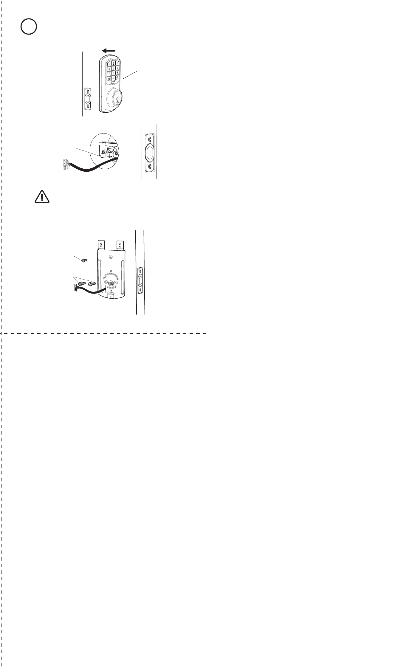
Install Interior Assembly
6
Install Interior Assembly5
C
B
Carefully insert control wire
into the wire connector
Work with the door open
NOTE: Make sure the Knob is in the Vertical position.
Be careful not to pinch the control wire when assembling
Feed excess wire back into the slot.
I
G
C
B
Test the lock
Lock and unlock using the knob make sure the latch is opening and
closing easily. If not, go back to step 2 and ensure you followed the steps correctly
Example
Note: Let lock operation complete
before attempting another action
NOTE: Make sure the connector lines up with the control wire
Regulatory Compliance
This product complies with standards established by following regulatory bodies:
- Federal Communications Commission (FCC)
IMPORTANT! Changes or modications not expressly approved by the manufacturer
could void the user’s authority to operate the equipment.
FCC WARNING:
Warning: Changes or modications to this unit not expressly approved by the
party responsible for compliance could void the user’s authority to operate the
equipment.
FCC STATEMENT
NOTE: This equipment has been tested and found to comply with the limits for a
Class B digital device, pursuant to Part 15 of the FCC Rules. These limits are
designed to provide reasonable protection against harmful interference in a
residential installation. This equipment generates uses and can radiate radio
frequency energy and, if not installed and used in accordance with the
instructions, may cause harmful interference to radio communications.
However, there is no guarantee that interference will not occur in a particular
installation. If this equipment does cause harmful interference to radio or
television reception, which can be determined by turning the equipment off and
on, the user is encouraged to try to correct the interference by one or more of the
following measures:
• Reorient or relocate the receiving antenna.
• Increase the separation between the equipment and receiver.
• Connect the equipment into an outlet on a circuit different from that to which
the receiver is connected.
• Consult the dealer or an experienced radio/TV technician for help.
This equipment complies with FCC radiation exposure limits set forth for an
uncontrolled environment. This equipment should be installed and operated with
a minimum distance of 20cm between the radiator & your body. This transmitter
must not be co-located or operating in conjunction with any other antenna or
transmitter.
A
H I J K L M
B C
D
E F
M1743010 1743011 E V0
Installation Overview
Congratulations, You have Installed the
Trubolt Orion Wi-Fi Deadbolt
(1743010 1743011)
Turn Sheet over for Programing Instructions.
8
Install Enclosed Latch and Strike Plate321
Refer to Template for
Door Prep Instructions
F
NOTE: Skip this step if your door comes with pre-drilled holes.
ENGLISH
Package Includes:
1 - Exterior Faceplate
1 - Interior Faceplate
1 - User Guide
2 - Keys
1 - Strike Plate
1 - Mounting Plate
1 - Latch
1 - 1 3/8” Screws
2 - 5/16” Screws
2 - 1 “ Screws
4 - 3/4”Screws
1 - Optional Set Screw
Read this manual carefully before installing and operating!
3/4” Screws1” Screws 5/16” Screws1 3/8” Screws
Exterior Faceplate Interior Faceplate
User Guide
Keys
Latch
Model 1743010 1743011
Optional Set Screw
Please carefully check the above list to confirm all items have been received. If any items are
missing, please contact Consumer Assistance. (See page for contact information)
Mounting Plate
Preparing Door
7 Install Batteries and Cover
Strike Plate
C
Wi-Fi Enabled Deadbolt with Keypad
Orion
G
A
D
E
F
K
H
L
B
J
J
M
J
Strike Plate
E
J
2-3/4” position
E
2-3/8” position
Do Not Over Tighten
TO CONVERT FROM 2-3/8” (60mm) BACKSET TO 2-3/4” (70mm) BACKSET
1. Hold latch with numbers facing forward and thumb pressing on the bolt.
2. Rotate the cylinder cover clockwise.
3. Pull and twist the extension plate all the way out.
4. Rotate the cylinder counter clockwise so that the marking aligns with
the 2-3/4” position indicator.
NOTE: Do not extend Cylindrical Cover past 2-3/4” (70mm)
NOTE: Screw Mounting Post (L) into holes on Mounting Plate (C)
M
This Electronic lock requires (4) High Quality AA Alkaline
batteries. When all 4 batteries are installed in the correct
position, you should hear 2 beeps and the keypad will
illuminate.
The Lock motor will engage and do a series of locking and
unlocking motions in order to automatically determine your
door “Handing” (left or right handed door).
The lock will beep and the keypad will flash signaling success.
NOTE: Do not touch the Keypad until the light turns off.
Do not use rechargeable batteries or non-alkaline batteries.
Test unlocking
Press 1-2-3-4-5-6-
Before Opening Door
Let Motor Complete Cycle
Testing Operation
Test the lock button with door open
Install Exterior Assembly4
A
Secure mounting
plate to door
K (optional)
H
C
Check that the Rubber Gasket is secured on the Exterior
Assembly. Insert the Exterior Assembly onto the door with
the tailpiece going through the Deadbolt Latch Set in the
VERTICAL POSITION and the Latch Retracted. Route the
Control Wire through the door under the Deadbolt Latch
Set.
AA
Install Interior Assembly
6
Install Interior Assembly5
C
B
Carefully insert control wire
into the wire connector
Work with the door open
NOTE: Make sure the Knob is in the Vertical position.
Be careful not to pinch the control wire when assembling
Feed excess wire back into the slot.
I
G
C
B
Test the lock
Lock and unlock using the knob make sure the latch is opening and
closing easily. If not, go back to step 2 and ensure you followed the steps correctly
Example
Note: Let lock operation complete
before attempting another action
NOTE: Make sure the connector lines up with the control wire
Regulatory Compliance
This product complies with standards established by following regulatory bodies:
- Federal Communications Commission (FCC)
IMPORTANT! Changes or modications not expressly approved by the manufacturer
could void the user’s authority to operate the equipment.
FCC WARNING:
Warning: Changes or modications to this unit not expressly approved by the
party responsible for compliance could void the user’s authority to operate the
equipment.
FCC STATEMENT
NOTE: This equipment has been tested and found to comply with the limits for a
Class B digital device, pursuant to Part 15 of the FCC Rules. These limits are
designed to provide reasonable protection against harmful interference in a
residential installation. This equipment generates uses and can radiate radio
frequency energy and, if not installed and used in accordance with the
instructions, may cause harmful interference to radio communications.
However, there is no guarantee that interference will not occur in a particular
installation. If this equipment does cause harmful interference to radio or
television reception, which can be determined by turning the equipment off and
on, the user is encouraged to try to correct the interference by one or more of the
following measures:
• Reorient or relocate the receiving antenna.
• Increase the separation between the equipment and receiver.
• Connect the equipment into an outlet on a circuit different from that to which
the receiver is connected.
• Consult the dealer or an experienced radio/TV technician for help.
This equipment complies with FCC radiation exposure limits set forth for an
uncontrolled environment. This equipment should be installed and operated with
a minimum distance of 20cm between the radiator & your body. This transmitter
must not be co-located or operating in conjunction with any other antenna or
transmitter.
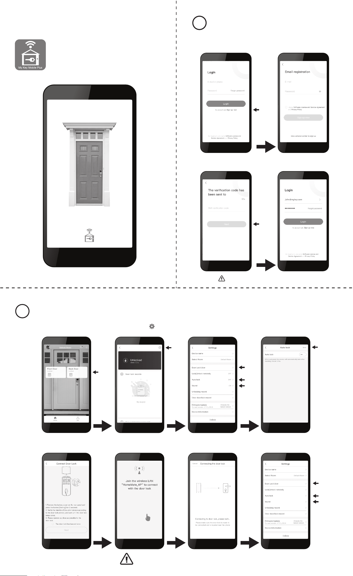
Programming Instructions Register an Account11
Change Lock Settings
4 5
Additional Functions
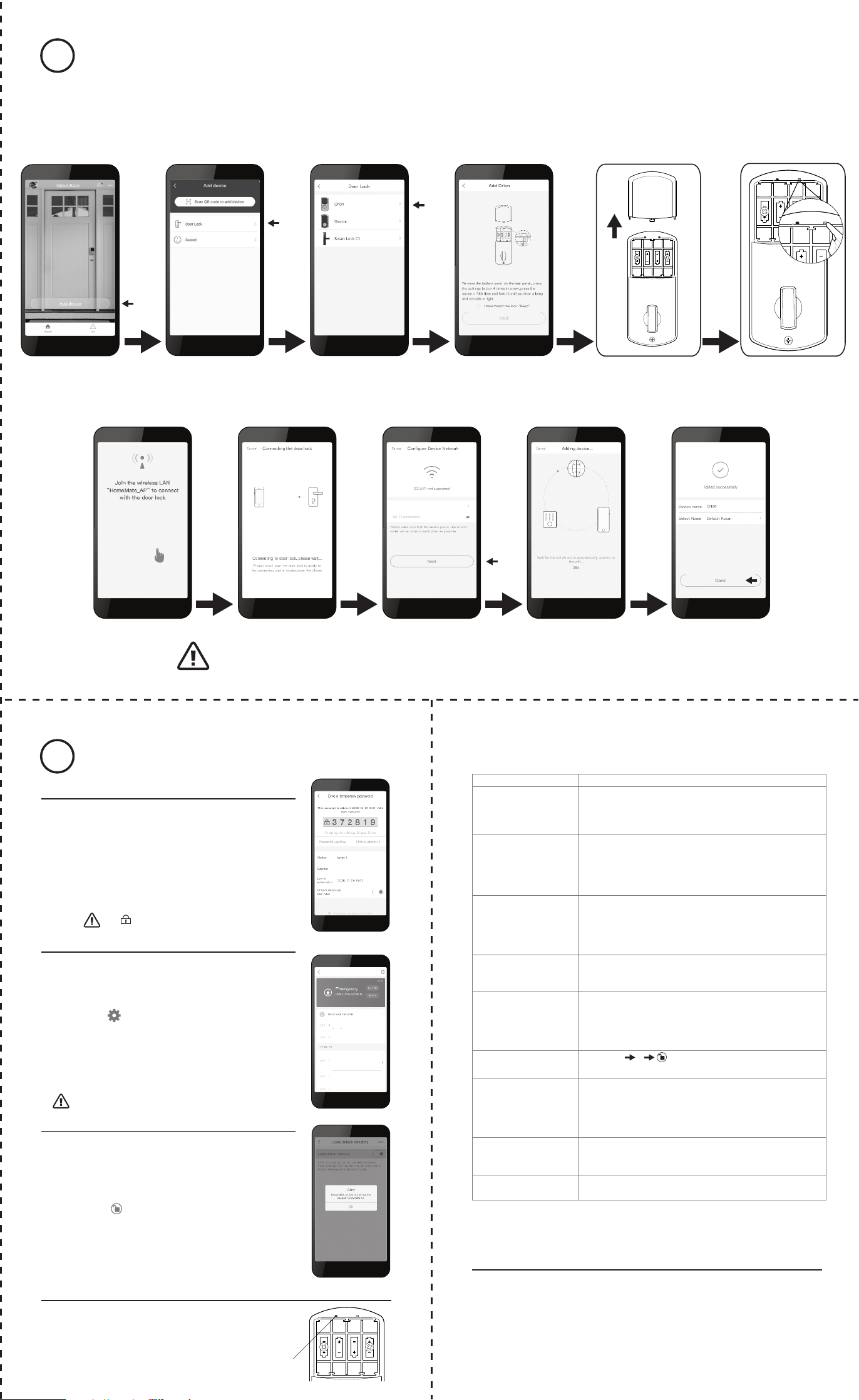
How to Add a Lock - Must Complete Setup to Use App Features
2
1743010 1743011 V0 E
Troubleshooting
Contact Us First! Do Not Return to Store
1. Press “Sign up now” on the login screen 2. Enter your E-mail or press
“Use a phone number” and
preferred password
3. Enter the Verication code you received
via E-mail or text
4. Success! Use the selected password to
log into the My Key Mobile Plus App
1. Remove battery cover 2. Hold the “Setup” button for 2
seconds until the Keypad lights up
3. Enter a new 6 digit admin code
The lock will ash Green and beep letting you know the process was successful
4. Repeat the 6 digit admin code
to reconrm
Download My Key Mobile Plus
from the APP store or Google Play
Limited 1-Year Electronic Warranty
Limited Lifetime Mechanical and Finish Warranty
This Tru-Bolt® product comes with a 1-Year Limited Warranty on Electronic
Parts and a Limited Lifetime Mechanical and Finish Warranty against defects
in materials and workmanship under normal use to the original residential
user. Proof of purchase and ownership is required for the warranty to be in effect.
This warranty is non transferable and applies to the original purchaser
only, as long as the original purchaser occupies the residential premises upon
which the product[s] was originally installed. This warranty DOES NOT
COVER removal and reinstallation of product[s], scratches, abrasions,
deterioration due to the use of paints, solvents or other chemicals, abuse,
misuse, or product[s] used in commercial applications, does not cover any
losses, injuries to persons/property or costs, and shipping and freight
expenses required to return product[s]. In no event shall Tru-Bolt® be liable
for any special, incidental or consequential damages. If this produ
ct[s] is
considered a consumer product, please be advised that some local and state
laws do not allow limitations on incidental or consequential damages or how
long an implied warranty lasts, so that the above limitations may not fully apply.
Refer to your local laws for your specic rights under this warranty. If
there are any problems please call our customer service with any questions or
concerns.
DO NOT RETURN TO STORE
For questions / comments, technical assistance or repair parts – please call toll
free at: 1-800-860-1677 x 1801 (M-F 7am-5pm PST)
Don’t forget to register your lock at www.Truboltlocks.info for updates.
Issue Solution
Lock will not function
electronically.
• Check that all batteries are new high quality Alkaline Batteries
• Check for proper polarity (+ -) of all batteries
• Check that the Control Wire is attached to the Interior Assembly
• Remove 1 battery for 5 seconds to reset lock. Reinstall battery
Lock gives error signal
when opening or locking.
Latch will not extend
or retract completely when
closed.
• Unlock door using Key or Interior Knob
• While door is open, check that the Latch operates smoothly
• Check for proper alignment of the strike plate, adjust as needed to
assure there is no binding against the Latch
The Latch is sticking. Installation screws of the lock may be too tight and have to be loosened
• Remove Interior Assembly
• Slightly loosen the Mounting plate screws
• Lock and unlock using the Key
• Reattach Control Wire and Interior Assembly
App screen is stuck on
“Connecting the Door Lock”
• Wait a few minutes as the lock server may be busy
• Hit “Cancel” and attempt to connect again, this may complete
the process
The App is unable to
connect to a lock.
The Lock is ofine.
• Make sure your phone has wi is enabled
• If “HomeMate_AP” is not automatically chosen then you must
manually select it as your wi network to modify settings
• Hit “Cancel” and attempt to connect again, this may complete
the process
Lock not showing correct
locked/ unlocked status
in App.
• Back out of menus until you are in the home screen, then reselect
your lock
• Manually lock and unlock the lock
• Lock and unlock using the keypad
• Wait a few minutes as the lock server may be busy
Forgotten Password. • On the home screen select the Forgot Password option, then
select the account type that was registered, and follow the
prompts to create a new Password
Latch is not locking in
inclement weather.
• Push or pull door to direct latch
• Readjust latch for smoother operations
EMAIL: [email protected]
WEBSITE: www.truboltlocks.info
ADDRESS: Consumer Assistance Dept.
Lewis Hyman, Inc.
860 East Sandhill Avenue
Carson, CA 90746 USA
TELEPHONE: US/Canada 800-860-1677 Ext. 1801 (Toll Free)
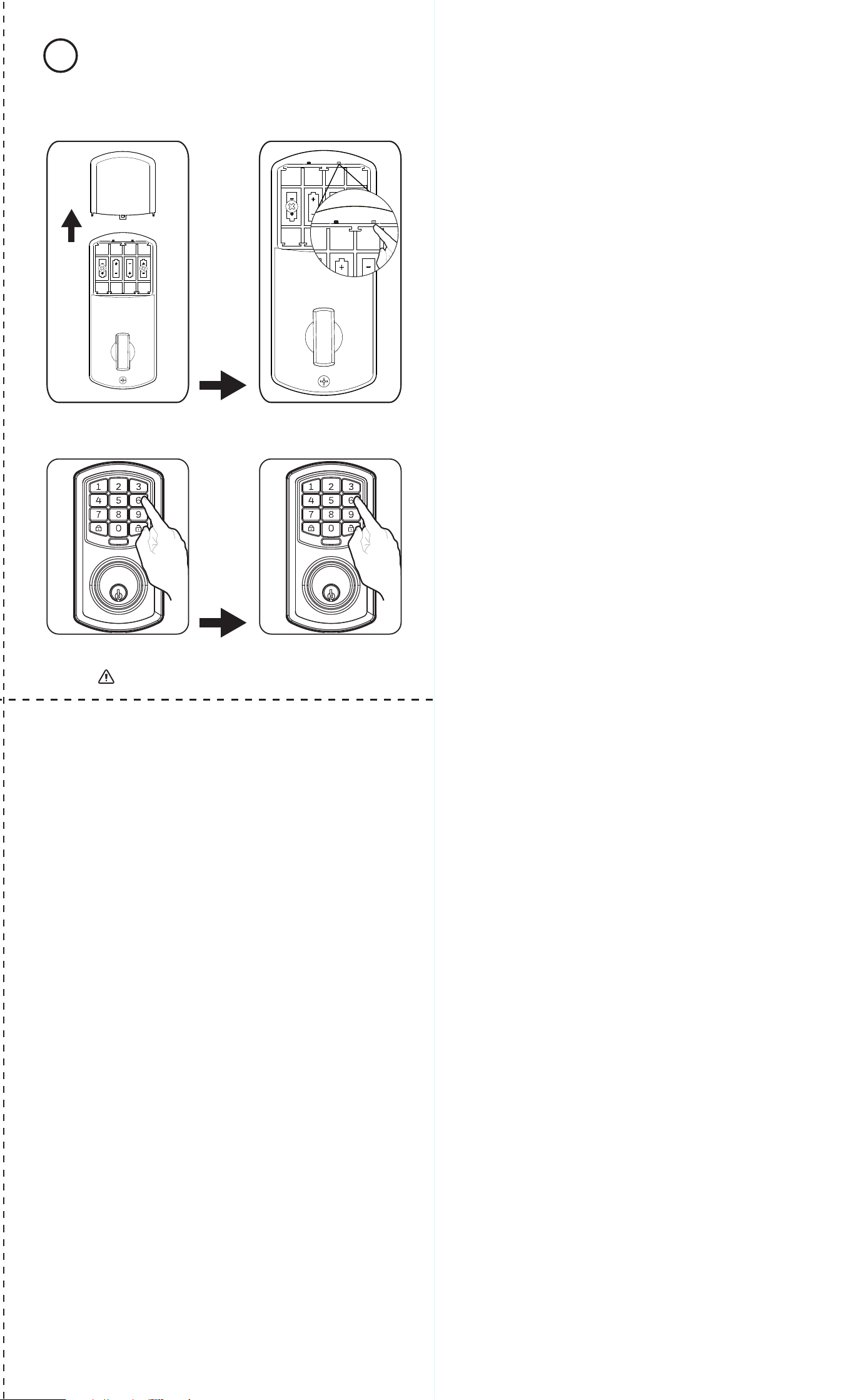
Restore Factory Settings
Remove cover, The reset button is located inside the back panel.
Press the reset button on the PCB board 4 times and then press and hold
for a 5th until you hear one beep.
This indicates that the lock has been reset to the Factory Settings.
Package Warranty:
Limited Lifetime Mechanical & Finish Warranty:
This Tru-Bolt® product[s] comes with a 1-Year Limited Warranty on
Electronic Parts and a Limited Lifetime Mechanical and Finish Warranty
against defects in materials and workmanship under normal use to the
original residential user. If there are any problems please call our customer
service with any questions or concerns. See installation instructions for full
terms and conditions.
You can use the APP to use these features
(XXX) XXX-XXXX
Reset Setup
Reset Setup
Change Admin Passcode
You must rst set a new admin password in order to change any lock settings
3
1. Press “Add device” on
the home screen
Reset Setup
Reset Setup
Network Name.
2. Press “Door Lock” 3. Select your Lock from
the list
4. Follow the App on screen instructions to put the lock into setup mode
5. Continue to follow the on screen instructions 6. Select wi network and enter your wi password 7. Choose a Custom name
for your lock
Make sure your phone is on the Homemate _AP network
The lock flashes blue during this pairing period, once successful the lock will beep and the blue light will turn off.
If pairing is unsuccessful please try again starting at step 3
Write your password down so you don’t forget Write your admin passcode down so you don’t forget
1. Select your lock
Home Screen
3. Select the setting you want
to change
4. Set your preference and hit
“Save”
1
Orion
2. Press the settings “ ” in the
top right of the lock screen
5. Follow the on screen instructions to put the lock into setup mode 6. Customize your settings during
this 60 sec period
Add users
Autolock Settings
Sound On/Off
1
On
Orion
On
On
0
,this will reconnect the lock
Create Temporary Passcodes
1. Select the lock from the home screen
2. Press “Give a temporary password”
3. Press the “+” in the top right corner of the screen
4. Customize the name, number of uses, and the period of
time in which the password will remain valid
5. Press “Get a temporary password”
6. Copy temporary password to send via SMS
or write it down
Reset Button
Reset Setup
John
This lock includes a unique “Emergency Password” feature.
An emergency password will send an Emergency Alert to
all group users.
1. Select the lock from the home screen
2. Press the “ ” in the top right corner of the screen
3. Select Door Lock User
4. Select the User that you wish to give a code
5. Press the red “Emergency Password” button
6. Follow the on screen instructions to add an
Emergency Password for this user.
Emergency Password
Example Unlocked the Door with the
Emergency Password!
Example uses password to unlock
the door.
Example uses password to unlock
the door.
Example uses password to unlock
the door.
XXXXXXXX assigned a temporary
password to XXXXX, which is
valid until XX-XX-XX XX:XX and
valid for several uses
Remote Unlocking
Remote unlocking is a feature that allows you to lock and
unlock from anywhere. This feature increases power
consumption and should only be used in special situations.
Disabling this feature increases battery life.
Enable:
1. Press 000+ on the lock keypad
This setting can only be changed on the keypad
Disable:
1. Select “Lock/Unlock remotely” on the lock setting screen
2. Toggle “Lock/Unlock remotely” to “Off” and press save.
This setting can be changed remotely
The is part of the temporary passcode
Make sure your phone is on the Homemate _AP network
If unsuccessful please try again starting at step 4
• Press 1
• Remove 1 battery for 5 seconds to reset lock. Reinstall battery
Alert will be sent to all users in the group except
the selected “associated group members”.
Programming Instructions Register an Account11
Change Lock Settings
4 5
Additional Functions
How to Add a Lock - Must Complete Setup to Use App Features
2
1743010 1743011 V0 E
Troubleshooting
Contact Us First! Do Not Return to Store
1. Press “Sign up now” on the login screen 2. Enter your E-mail or press
“Use a phone number” and
preferred password
3. Enter the Verication code you received
via E-mail or text
4. Success! Use the selected password to
log into the My Key Mobile Plus App
1. Remove battery cover 2. Hold the “Setup” button for 2
seconds until the Keypad lights up
3. Enter a new 6 digit admin code
The lock will ash Green and beep letting you know the process was successful
4. Repeat the 6 digit admin code
to reconrm
Download My Key Mobile Plus
from the APP store or Google Play
Limited 1-Year Electronic Warranty
Limited Lifetime Mechanical and Finish Warranty
This Tru-Bolt® product comes with a 1-Year Limited Warranty on Electronic
Parts and a Limited Lifetime Mechanical and Finish Warranty against defects
in materials and workmanship under normal use to the original residential
user. Proof of purchase and ownership is required for the warranty to be in effect.
This warranty is non transferable and applies to the original purchaser
only, as long as the original purchaser occupies the residential premises upon
which the product[s] was originally installed. This warranty DOES NOT
COVER removal and reinstallation of product[s], scratches, abrasions,
deterioration due to the use of paints, solvents or other chemicals, abuse,
misuse, or product[s] used in commercial applications, does not cover any
losses, injuries to persons/property or costs, and shipping and freight
expenses required to return product[s]. In no event shall Tru-Bolt® be liable
for any special, incidental or consequential damages. If this produ
ct[s] is
considered a consumer product, please be advised that some local and state
laws do not allow limitations on incidental or consequential damages or how
long an implied warranty lasts, so that the above limitations may not fully apply.
Refer to your local laws for your specic rights under this warranty. If
there are any problems please call our customer service with any questions or
concerns.
DO NOT RETURN TO STORE
For questions / comments, technical assistance or repair parts – please call toll
free at: 1-800-860-1677 x 1801 (M-F 7am-5pm PST)
Don’t forget to register your lock at www.Truboltlocks.info for updates.
Issue Solution
Lock will not function
electronically.
• Check that all batteries are new high quality Alkaline Batteries
• Check for proper polarity (+ -) of all batteries
• Check that the Control Wire is attached to the Interior Assembly
• Remove 1 battery for 5 seconds to reset lock. Reinstall battery
Lock gives error signal
when opening or locking.
Latch will not extend
or retract completely when
closed.
• Unlock door using Key or Interior Knob
• While door is open, check that the Latch operates smoothly
• Check for proper alignment of the strike plate, adjust as needed to
assure there is no binding against the Latch
The Latch is sticking. Installation screws of the lock may be too tight and have to be loosened
• Remove Interior Assembly
• Slightly loosen the Mounting plate screws
• Lock and unlock using the Key
• Reattach Control Wire and Interior Assembly
App screen is stuck on
“Connecting the Door Lock”
• Wait a few minutes as the lock server may be busy
• Hit “Cancel” and attempt to connect again, this may complete
the process
The App is unable to
connect to a lock.
The Lock is ofine.
• Make sure your phone has wi is enabled
• If “HomeMate_AP” is not automatically chosen then you must
manually select it as your wi network to modify settings
• Hit “Cancel” and attempt to connect again, this may complete
the process
Lock not showing correct
locked/ unlocked status
in App.
• Back out of menus until you are in the home screen, then reselect
your lock
• Manually lock and unlock the lock
• Lock and unlock using the keypad
• Wait a few minutes as the lock server may be busy
Forgotten Password. • On the home screen select the Forgot Password option, then
select the account type that was registered, and follow the
prompts to create a new Password
Latch is not locking in
inclement weather.
• Push or pull door to direct latch
• Readjust latch for smoother operations
EMAIL: [email protected]
WEBSITE: www.truboltlocks.info
ADDRESS: Consumer Assistance Dept.
Lewis Hyman, Inc.
860 East Sandhill Avenue
Carson, CA 90746 USA
TELEPHONE: US/Canada 800-860-1677 Ext. 1801 (Toll Free)
Restore Factory Settings
Remove cover, The reset button is located inside the back panel.
Press the reset button on the PCB board 4 times and then press and hold
for a 5th until you hear one beep.
This indicates that the lock has been reset to the Factory Settings.
Package Warranty:
Limited Lifetime Mechanical & Finish Warranty:
This Tru-Bolt® product[s] comes with a 1-Year Limited Warranty on
Electronic Parts and a Limited Lifetime Mechanical and Finish Warranty
against defects in materials and workmanship under normal use to the
original residential user. If there are any problems please call our customer
service with any questions or concerns. See installation instructions for full
terms and conditions.
You can use the APP to use these features
(XXX) XXX-XXXX
Reset Setup
Reset Setup
Change Admin Passcode
You must rst set a new admin password in order to change any lock settings
3
1. Press “Add device” on
the home screen
Reset Setup
Reset Setup
Network Name.
2. Press “Door Lock” 3. Select your Lock from
the list
4. Follow the App on screen instructions to put the lock into setup mode
5. Continue to follow the on screen instructions 6. Select wi network and enter your wi password 7. Choose a Custom name
for your lock
Make sure your phone is on the Homemate _AP network
The lock flashes blue during this pairing period, once successful the lock will beep and the blue light will turn off.
If pairing is unsuccessful please try again starting at step 3
Write your password down so you don’t forget Write your admin passcode down so you don’t forget
1. Select your lock
Home Screen
3. Select the setting you want
to change
4. Set your preference and hit
“Save”
1
Orion
2. Press the settings “ ” in the
top right of the lock screen
5. Follow the on screen instructions to put the lock into setup mode 6. Customize your settings during
this 60 sec period
Add users
Autolock Settings
Sound On/Off
1
On
Orion
On
On
0
,this will reconnect the lock
Create Temporary Passcodes
1. Select the lock from the home screen
2. Press “Give a temporary password”
3. Press the “+” in the top right corner of the screen
4. Customize the name, number of uses, and the period of
time in which the password will remain valid
5. Press “Get a temporary password”
6. Copy temporary password to send via SMS
or write it down
Reset Button
Reset Setup
John
This lock includes a unique “Emergency Password” feature.
An emergency password will send an Emergency Alert to
all group users.
1. Select the lock from the home screen
2. Press the “ ” in the top right corner of the screen
3. Select Door Lock User
4. Select the User that you wish to give a code
5. Press the red “Emergency Password” button
6. Follow the on screen instructions to add an
Emergency Password for this user.
Emergency Password
Example Unlocked the Door with the
Emergency Password!
Example uses password to unlock
the door.
Example uses password to unlock
the door.
Example uses password to unlock
the door.
XXXXXXXX assigned a temporary
password to XXXXX, which is
valid until XX-XX-XX XX:XX and
valid for several uses
Remote Unlocking
Remote unlocking is a feature that allows you to lock and
unlock from anywhere. This feature increases power
consumption and should only be used in special situations.
Disabling this feature increases battery life.
Enable:
1. Press 000+ on the lock keypad
This setting can only be changed on the keypad
Disable:
1. Select “Lock/Unlock remotely” on the lock setting screen
2. Toggle “Lock/Unlock remotely” to “Off” and press save.
This setting can be changed remotely
The is part of the temporary passcode
Make sure your phone is on the Homemate _AP network
If unsuccessful please try again starting at step 4
• Press 1
• Remove 1 battery for 5 seconds to reset lock. Reinstall battery
Alert will be sent to all users in the group except
the selected “associated group members”.