A
H I J K
B
C D E
F G
Installation Overview
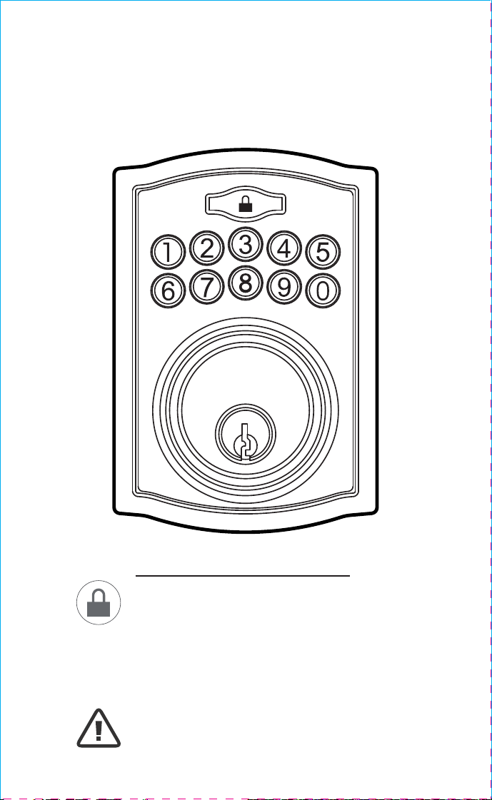
Congratulations, You have Installed the
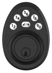
Trubolt Phoenix Digital Deadbolt
(1741018, 1741020)
Turn Sheet over for Programing Instructions.
1
ENGLISH
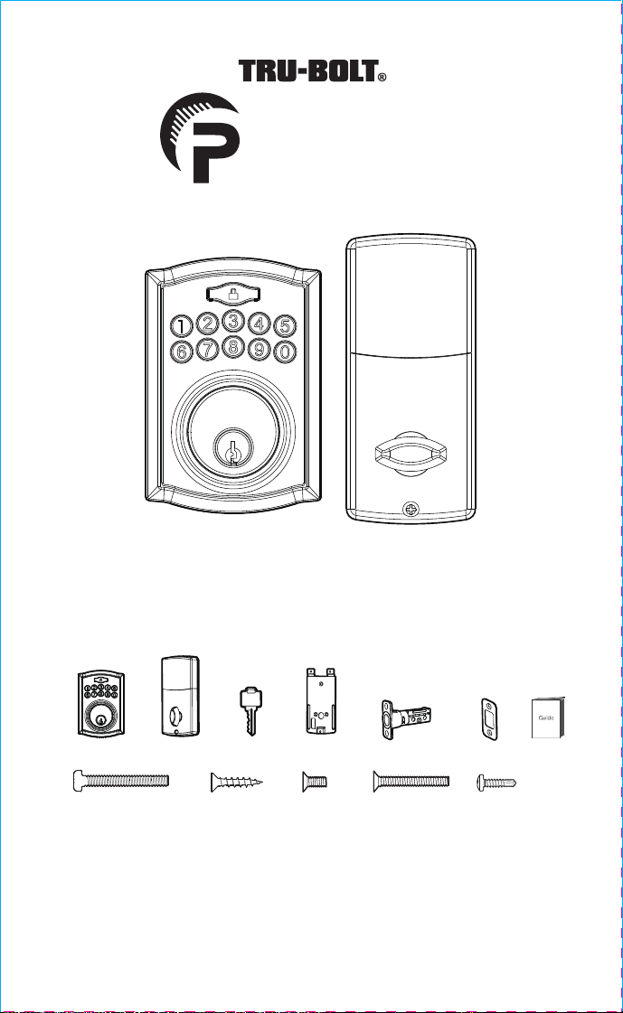
Package Includes:
1 - Exterior Faceplate
1 - Interior Faceplate
1 - User Guide
2 - Keys
1 - Strike Plate
1 - Mounting Plate
1 - Adjustable Latch
1 - 1 3/8” Screws
4 - 3/4” Screws
1 - Optional Set Screw
2 - Mounting Post
Read this manual carefully before installing and operating!
3/4” Screws 5/16” Screws 7/8” Screws1” Screws
Exterior Faceplate Iinterior Faceplate
User Guide
Override Key
Adjustable LatchMounting Plate
Models 1741018, 1741020
L
Please carefully check the above list to confirm all items have been received. If any items are
missing, please contact Consumer Assistance. (See page for contact information)
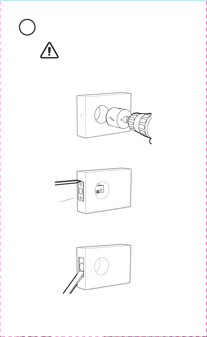
2 Preparing Door
Strike plate
DO NOT RETURN TO STORE!
If any parts are missing or damaged, please call Customer Service
Toll free at 1-800-860-1677 (Toll Free, M-F 7am – 5pm PST).
Online installation videos can be viewed at TruBoltLocks.info.
Don’t forget to register your lock at TruBoltLocks.info for updates.
DO NOT RETURN TO STORE!
If any parts are missing or damaged, please call Customer Service
Toll free at 1-800-860-1677 (Toll Free, M-F 7am – 5pm PST).
Online installation videos can be viewed at TruBoltLocks.info.
Don’t forget to register your lock at www.TruBoltLocks.info for updates.
M1741018, 1741020 E V0
Refer to Template for Door Prep
Instructions Included in packaging
F
NOTE: Skip this step if your door comes with pre-drilled holes.
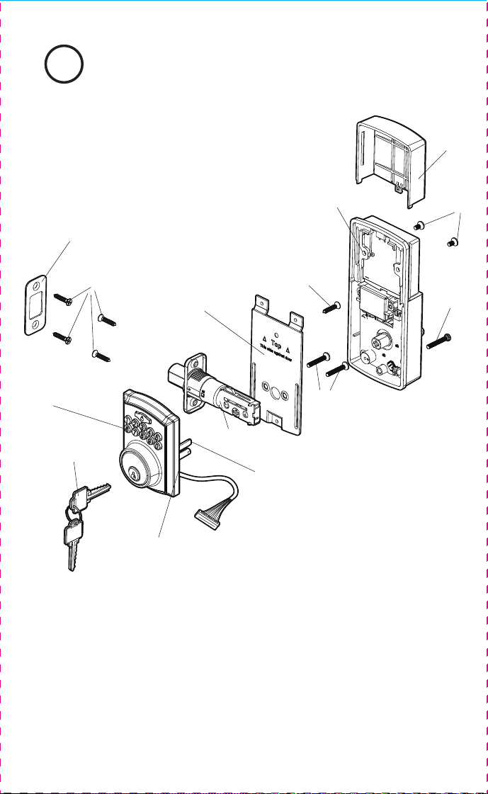
A
C
Control wire
Tailpiece
D
F
I
J
H
K
L
E
B
B
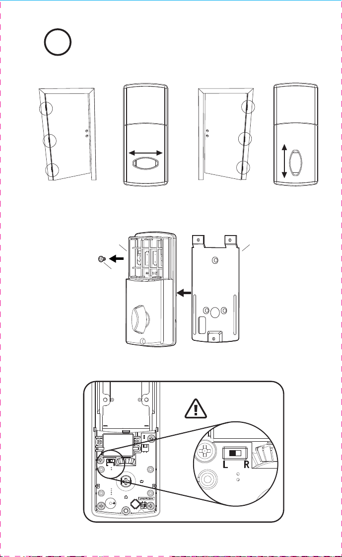
Determine Door “Handing”4
DB
Remove Screw to Remove Mounting Plate
Right Handed Door Turn Knob VerticalLeft Handed Door Turn Knob Horizontal
OR
View from outside of door
Set entry Switch to
Correct Direction
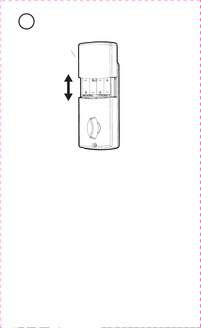
Install Batteries and Cover
8
B
This Electronic lock requires (4) High Quality AA Alkaline
batteries. When all 4 batteries are installed in the correct
position, you should hear 2 beeps and the keypad will
illuminate green.
NOTE: Do not touch the Keypad until the green light turns off.
Do not use rechargeable batteries or non-alkaline batteries.
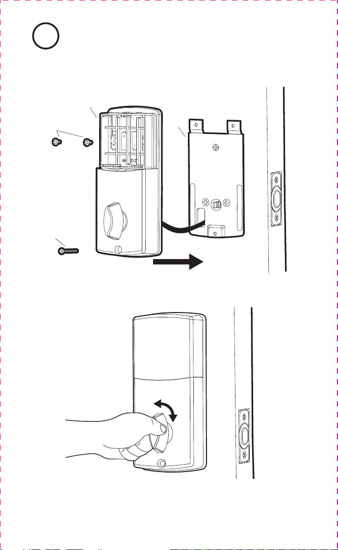
Install Interior Assembly7
J
H
D
B
Test the lock
Lock and unlock using the knob make sure the latch is opening and
closing easily. If not, go back to step 2 and ensure you followed the steps
NOTE: Make sure the Knob is in the correct position.
(Horizontal for Left Door and Vertical for Right Door)
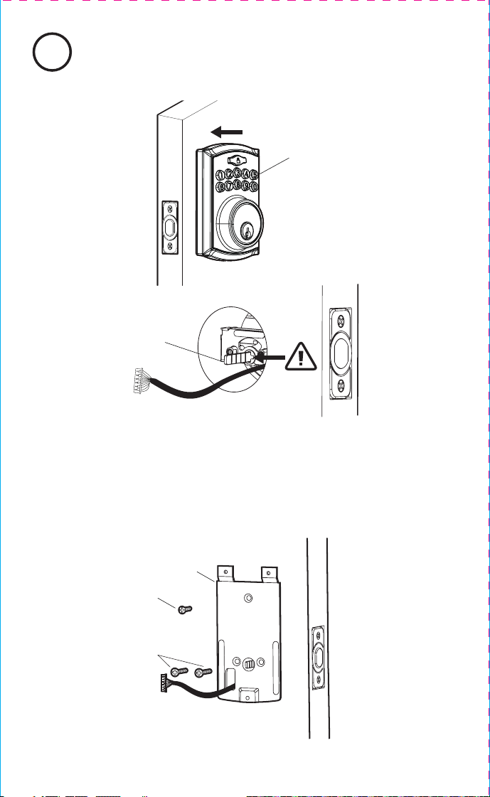
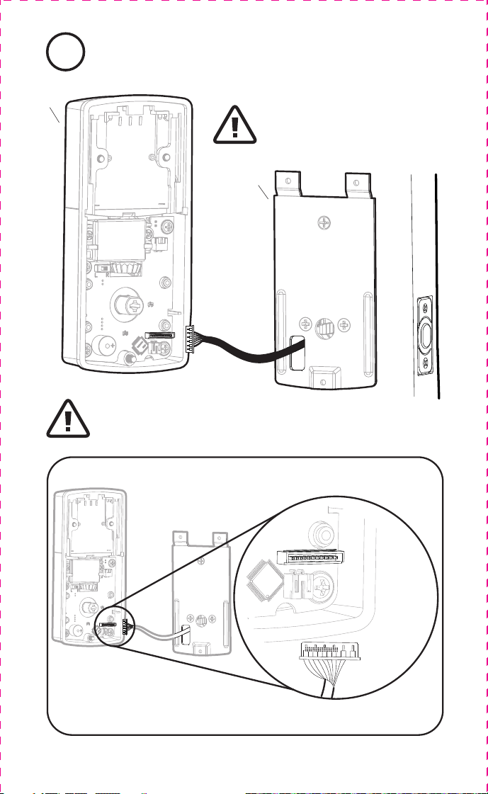
Install Interior Assembly6
D
B
Carefully insert control wire
into the wire connector
Work with the door open
NOTE: Make sure the connector dots line up with the dots on the wire
Install Exterior Assembly5
Tailpiece
A
Secure mounting
plate to door
I (optional)
K
D
Check that the Rubber Gasket is secured on the Exterior
Assembly. Insert the Exterior Assembly onto the door with
the tailpiece going through the Deadbolt Latch Set in the
VERTICAL POSITION. Route the Control Wire through the
door under the Deadbolt Latch Set.
hoenix
Digital Deadbolt with Keypad
J
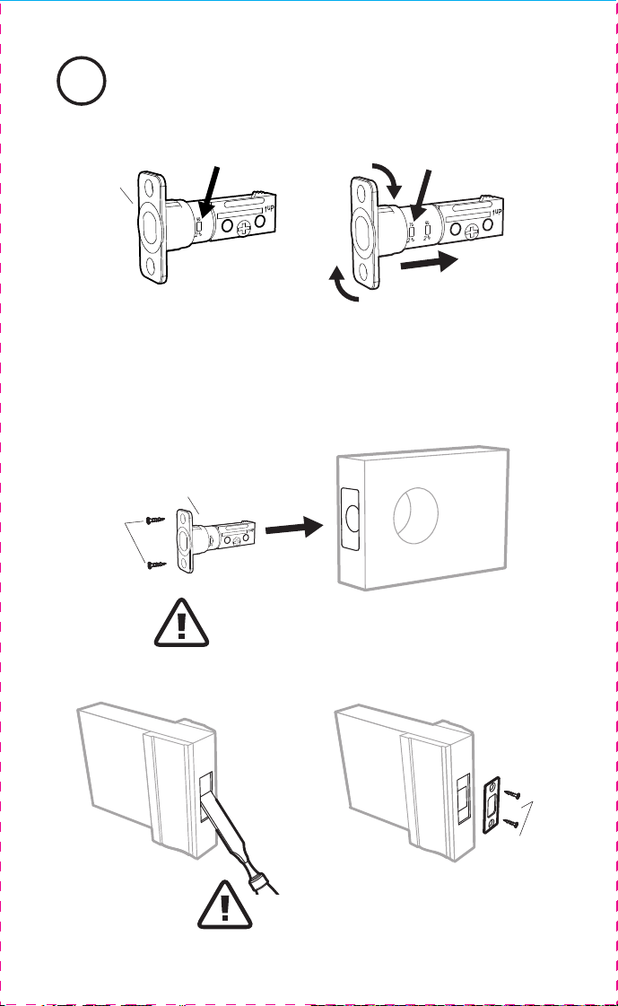
Install Enclosed Latch and Strike Plate3
J
Strike Plate
E
I
2-3/4” position
E
2-3/8” position
Do Not Over Tighten
Deadbolt Latch Must Be
Retracted During Installation
TO CONVERT FROM 2-3/8” (60mm) BACKSET TO 2-3/4” (70mm) BACKSET
1. Hold latch with numbers facing forward and thumb pressing on the bolt.
2. Rotate the cylinder cover clockwise.
3. Pull and twist the extension plate all the way out.
4. Rotate the cylinder counter clockwise so that the marking aligns with
the 2-3/4” position indicator.
NOTE: Do not extend Cylindrical Cover past 2-3/4” (70mm)
Optional Set Screw
A
H I J K
B
C D E
F G
Installation Overview
Congratulations, You have Installed the
Trubolt Phoenix Digital Deadbolt
(1741018, 1741020)
Turn Sheet over for Programing Instructions.
1
ENGLISH
Package Includes:
1 - Exterior Faceplate
1 - Interior Faceplate
1 - User Guide
2 - Keys
1 - Strike Plate
1 - Mounting Plate
1 - Adjustable Latch
1 - 1 3/8” Screws
4 - 3/4” Screws
1 - Optional Set Screw
2 - Mounting Post
Read this manual carefully before installing and operating!
3/4” Screws 5/16” Screws 7/8” Screws1” Screws
Exterior Faceplate Iinterior Faceplate
User Guide
Override Key
Adjustable LatchMounting Plate
Models 1741018, 1741020
L
Please carefully check the above list to confirm all items have been received. If any items are
missing, please contact Consumer Assistance. (See page for contact information)
2 Preparing Door
Strike plate
DO NOT RETURN TO STORE!
If any parts are missing or damaged, please call Customer Service
Toll free at 1-800-860-1677 (Toll Free, M-F 7am – 5pm PST).
Online installation videos can be viewed at TruBoltLocks.info.
Don’t forget to register your lock at TruBoltLocks.info for updates.
DO NOT RETURN TO STORE!
If any parts are missing or damaged, please call Customer Service
Toll free at 1-800-860-1677 (Toll Free, M-F 7am – 5pm PST).
Online installation videos can be viewed at TruBoltLocks.info.
Don’t forget to register your lock at www.TruBoltLocks.info for updates.
M1741018, 1741020 E V0
Refer to Template for Door Prep
Instructions Included in packaging
F
NOTE: Skip this step if your door comes with pre-drilled holes.
A
C
Control wire
Tailpiece
D
F
I
J
H
K
L
E
B
B
Determine Door “Handing”4
DB
Remove Screw to Remove Mounting Plate
Right Handed Door Turn Knob VerticalLeft Handed Door Turn Knob Horizontal
OR
View from outside of door
Set entry Switch to
Correct Direction
Install Batteries and Cover
8
B
This Electronic lock requires (4) High Quality AA Alkaline
batteries. When all 4 batteries are installed in the correct
position, you should hear 2 beeps and the keypad will
illuminate green.
NOTE: Do not touch the Keypad until the green light turns off.
Do not use rechargeable batteries or non-alkaline batteries.
Install Interior Assembly7
J
H
D
B
Test the lock
Lock and unlock using the knob make sure the latch is opening and
closing easily. If not, go back to step 2 and ensure you followed the steps
NOTE: Make sure the Knob is in the correct position.
(Horizontal for Left Door and Vertical for Right Door)
Install Interior Assembly6
D
B
Carefully insert control wire
into the wire connector
Work with the door open
NOTE: Make sure the connector dots line up with the dots on the wire
Install Exterior Assembly5
Tailpiece
A
Secure mounting
plate to door
I (optional)
K
D
Check that the Rubber Gasket is secured on the Exterior
Assembly. Insert the Exterior Assembly onto the door with
the tailpiece going through the Deadbolt Latch Set in the
VERTICAL POSITION. Route the Control Wire through the
door under the Deadbolt Latch Set.
hoenix
Digital Deadbolt with Keypad
J
Install Enclosed Latch and Strike Plate3
J
Strike Plate
E
I
2-3/4” position
E
2-3/8” position
Do Not Over Tighten
Deadbolt Latch Must Be
Retracted During Installation
TO CONVERT FROM 2-3/8” (60mm) BACKSET TO 2-3/4” (70mm) BACKSET
1. Hold latch with numbers facing forward and thumb pressing on the bolt.
2. Rotate the cylinder cover clockwise.
3. Pull and twist the extension plate all the way out.
4. Rotate the cylinder counter clockwise so that the marking aligns with
the 2-3/4” position indicator.
NOTE: Do not extend Cylindrical Cover past 2-3/4” (70mm)
Optional Set Screw

A
H I J K
B
C D E
F G
Installation Overview
Congratulations, You have Installed the
Trubolt Phoenix Digital Deadbolt
(1741018, 1741020)
Turn Sheet over for Programing Instructions.
1
ENGLISH
Package Includes:
1 - Exterior Faceplate
1 - Interior Faceplate
1 - User Guide
2 - Keys
1 - Strike Plate
1 - Mounting Plate
1 - Adjustable Latch
1 - 1 3/8” Screws
4 - 3/4” Screws
1 - Optional Set Screw
2 - Mounting Post
Read this manual carefully before installing and operating!
3/4” Screws 5/16” Screws 7/8” Screws1” Screws
Exterior Faceplate Iinterior Faceplate
User Guide
Override Key
Adjustable LatchMounting Plate
Models 1741018, 1741020
L
Please carefully check the above list to confirm all items have been received. If any items are
missing, please contact Consumer Assistance. (See page for contact information)
2 Preparing Door
Strike plate
DO NOT RETURN TO STORE!
If any parts are missing or damaged, please call Customer Service
Toll free at 1-800-860-1677 (Toll Free, M-F 7am – 5pm PST).
Online installation videos can be viewed at TruBoltLocks.info.
Don’t forget to register your lock at TruBoltLocks.info for updates.
DO NOT RETURN TO STORE!
If any parts are missing or damaged, please call Customer Service
Toll free at 1-800-860-1677 (Toll Free, M-F 7am – 5pm PST).
Online installation videos can be viewed at TruBoltLocks.info.
Don’t forget to register your lock at www.TruBoltLocks.info for updates.
M1741018, 1741020 E V0
Refer to Template for Door Prep
Instructions Included in packaging
F
NOTE: Skip this step if your door comes with pre-drilled holes.
A
C
Control wire
Tailpiece
D
F
I
J
H
K
L
E
B
B
Determine Door “Handing”4
DB
Remove Screw to Remove Mounting Plate
Right Handed Door Turn Knob VerticalLeft Handed Door Turn Knob Horizontal
OR
View from outside of door
Set entry Switch to
Correct Direction
Install Batteries and Cover
8
B
This Electronic lock requires (4) High Quality AA Alkaline
batteries. When all 4 batteries are installed in the correct
position, you should hear 2 beeps and the keypad will
illuminate green.
NOTE: Do not touch the Keypad until the green light turns off.
Do not use rechargeable batteries or non-alkaline batteries.
Install Interior Assembly7
J
H
D
B
Test the lock
Lock and unlock using the knob make sure the latch is opening and
closing easily. If not, go back to step 2 and ensure you followed the steps
NOTE: Make sure the Knob is in the correct position.
(Horizontal for Left Door and Vertical for Right Door)
Install Interior Assembly6
D
B
Carefully insert control wire
into the wire connector
Work with the door open
NOTE: Make sure the connector dots line up with the dots on the wire
Install Exterior Assembly5
Tailpiece
A
Secure mounting
plate to door
I (optional)
K
D
Check that the Rubber Gasket is secured on the Exterior
Assembly. Insert the Exterior Assembly onto the door with
the tailpiece going through the Deadbolt Latch Set in the
VERTICAL POSITION. Route the Control Wire through the
door under the Deadbolt Latch Set.
hoenix
Digital Deadbolt with Keypad
J
Install Enclosed Latch and Strike Plate3
J
Strike Plate
E
I
2-3/4” position
E
2-3/8” position
Do Not Over Tighten
Deadbolt Latch Must Be
Retracted During Installation
TO CONVERT FROM 2-3/8” (60mm) BACKSET TO 2-3/4” (70mm) BACKSET
1. Hold latch with numbers facing forward and thumb pressing on the bolt.
2. Rotate the cylinder cover clockwise.
3. Pull and twist the extension plate all the way out.
4. Rotate the cylinder counter clockwise so that the marking aligns with
the 2-3/4” position indicator.
NOTE: Do not extend Cylindrical Cover past 2-3/4” (70mm)
Optional Set Screw
M1741018, 1741020 E V0
Contact Us First! Do Not Return to Store
Don’t forget to register your lock at Truboltlocks.info for updates.
EMAIL: [email protected]
WEBSITE: www.truboltlocks.info
ADDRESS: Consumer Assistance Dept.
Lewis Hyman, Inc.
860 East Sandhill Avenue
Carson, CA 90746 USA
TELEPHONE: US/Canada 800-860-1677 Ext. 1801 (Toll Free)
Programming Instructions
Complete all the programming steps in the
programming mode within 5 seconds
Do not press keypad until keypad stops illuminating
To reset the lock to the original factory settings including the
Programming Code and all User Codes follow these steps:
1. Remove one battery for 10 seconds.
2. Reinsert the battery and wait for a long and short beep
3. Press 3 times within 3 seconds.
4. The lock will beep and the light indicator will turn green.
Restore Factory Settings
Low Battery Warning
Beeps and LED flashes red for 5 seconds. Replace with good
quality alkaline batteries.
Note: Removing batteries does not erase active Administrator
or User Codes.
Unlock / Valid programming: 1 long beep and LED illuminates green
Lock: 2 short beeps and LED illuminates red
2 short beeps and LED flashes red twiceInvalid Programming:
Low Voltage: Beeps for 5 seconds
3 long beeps LED flashes red three times
2 short beeps three times LED flashes red six times
Super Low Voltage:
4 Incorrect code entry attempts: 2 short beeps and LED illuminates red each attempt
Power on: 1 long beep and 1 short beep and LED illuminates green
Chip Reset:
Lock Error:
Repeat operation after Lock Error:
Consumer Friendly Message Guide
4 short beeps and LED flashes red four times
1 long beep and 1 short beep and LED illuminates green
(may occur several times or once in a while)
You can “mute” or turn the “sound on” on your lock by entering the following.
(Factory setting is sound on).
Sound On (1) - Hear 1 beep and Light Indicator illuminates green.
Sound Off (2) - Hear 1 beep and Light Indicator illuminates green.
6
1 or 2
SOUND ON AND OFF
AC
1 = Sound On
2 = Sound Off
7
Additional Programming Functions
6
Additional Programming Functions
Lock / Clear / Programming
Administrator Code
AC
With Vacation Mode enabled, the system enters into low-power consumption mode. During this mode, all
buttons and functions will be disabled until they are re-enabled (see steps below).
After inputting the correct code the
door will unlock immediately
Programming Symbols
Vacation Mode
SET OR CANCEL AUTO LOCK
You can set the lock to automatically close after each time the lock is opened. Time
value range = 20 - 900 seconds, enter the following:
Set Auto Lock:
Hear 1 beep and Light Indicator illuminates green.Hear 1 beep and Light Indicator illuminates green.
To cancel Auto Lock set the time to 00, enter the following:
Cancel Time Value Auto Lock:
Hear 1 beep and Light Indicator illuminates green.
55
5
Automatic Lock Function
TEMPORARILY DISABLE:
While in Auto-Lock mode, unlock door using , within 10 seconds you must turn the
locking knob by hand to the locked position, wait more than 2 seconds then turn the
locking knob back to the unlock position. The Auto-Lock mode is now disabled.
RESTORE:
To restore the Auto-Lock function, turn the locking knob by hand to the locked position,
wait more than 2 seconds or press the Lock button on the keypad.
AC
AC
AC
00
Time Value
NOTE: If you only press the for more than 3 seconds but do not input ,
the system will remain in Vacation Mode.
Secure Lock-out period
Warning sounds and LED flashes red after 4 incorrect code attempts: Keypad shuts
down for 60 seconds.
AC
Troubleshooting Warranty
Issue Solution
Latch Working
Backwards-
Lock unlocks when
lock button is pushed
or locks when unlock
button or code is
pushed
Direction switch is set to incorrect setting.
• Remove the Interior Assembly and move the switch to the opposite
direction on the rear of the assembly.
• Check that your switch is set in the correct position Left or Right
Handed door.
If Correct
• Rotate Interior Knob and reinstall Interior Assembly. Retest again
while holding Interior Assembly in place.
Interior Knob will not
turn
Knob or vertical tailpiece is installed in incorrect position.
• Remove Interior Assembly and reposition the Interior Knob. With the
Deadbolt Latch retracted verify that the tailpiece is vertical.
Lock will not function
electronically
• Check that all batteries are fresh high quality Alkaline Batteries.
• Check for proper polarity (+ -) of all batteries.
• Check that the Control Wire is attached to the Interior Assembly
and not damaged.
• Check each wire for loose or disconnected wires.
• Disconnect the wiring harness and reconnect the wiring harness.
Lock gives error signal
when opening or
locking and Deadbolt
Latch will not extend
or retract completely
when door is closed
• Unlock door using Key or Interior Knob. While door is open, check that the Deadbolt
Latch operates smoothly.
• Check for proper alignment of the strike plate, adjust as needed to assure there is
no binding against the Deadbolt Latch.
• Make sure tail piece is in the vertical position and straight up and down.
Deadbolt Latch is
sticking
Installation screws of the lock may be too tight and have to be loosened.
• Remove Interior Assembly.
• Slightly loosen the Mounting Plate screws.
• Lock and unlock using the Key.
• Reattach Control Wire and Interior Assembly.
Keypad not working
• Wait 60 seconds, keypad may be locked out due to incorrect code.
• Replace with 4 high quality alkaline batteries.
Keypad beeps and
LED flashes
• Replace with 4 high quality alkaline batteries.
DO NOT RETURN TO STORE!
If any parts are missing or damaged, please call Customer Service
Toll free at 1-800-860-1677 (Toll Free, M-F 7am – 5pm PST).
Online installation videos can be viewed at TruBoltLocks.info.
Don’t forget to register your lock at TruBoltLocks.info for updates.
Limited 1-Year Electronic Warranty
Limited Lifetime Mechanical and Finish Warranty
This Tru-Bolt® product comes with a 1-Year Limited Warranty on Electronic
Parts and a Limited Lifetime Mechanical and Finish Warranty against defects
in materials and workmanship under normal use to the original residential
user. Proof of purchase and ownership is required for the warranty to be in eect.
This warranty is non transferable and applies to the original purchaser
only, as long as the original purchaser occupies the residential premises upon
which the product[s] was originally installed. This warranty DOES NOT
COVER removal and reinstallation of product[s], scratches, abrasions,
deterioration due to the use of paints, solvents or other chemicals, abuse,
misuse, or product[s] used in commercial applications, does not cover any
losses, injuries to persons/property or costs, and shipping and freight
expenses required to return product[s]. In no event shall Tru-Bolt® be liable
for any special, incidental or consequential d
amages. If this product[s] is
considered a consumer product, please be advised that some local and state
laws do not allow limitations on incidental or consequential damages or how
long an implied warranty lasts, so that the above limitations may not fully apply.
Refer to your local laws for your specific rights under this warranty. If
there are any problems please call our customer service with any questions or
concerns.
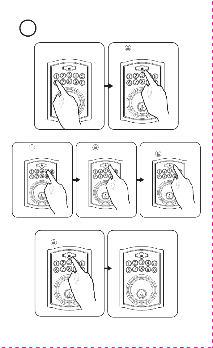
Creating Administrator Code11
Input 6 digit code
Press
Press Press
4
Repeat the 6 digit code
Press
Green light flashes
confirming success
Input Admin code
(default 123456)
Press
Adding a User Code2
Input Admin code
Press
Press
1
Green light flashes
confirming success
Repeat 4-8 digit
user code
Press
Press
Input new 4-8 digit
user code
Press
Input user number
between 01-50
Press
User Code 13 (4-8 digits) / /
User Code 14 (4-8 digits) / /
User Code 15 (4-8 digits) / /
User Code 16 (4-8 digits) / /
User Code 17 (4-8 digits) / /
User Code 18 (4-8 digits) / /
My Codes: Date Created
Programming Code
(6 digits) / /
User Code 02 (4-8 digits) / /
User Code 03 (4-8 digits) / /
User Code 04 (4-8 digits) / /
User Code 05 (4-8 digits) / /
User Code 06 (4-8 digits) / /
User Code 07 (4-8 digits) / /
User Code 09 (4-8 digits) / /
User Code 10 (4-8 digits) / /
User Code 11 (4-8 digits) / /
User Code 12 (4-8 digits) / /
PROGRAMMING RECORD
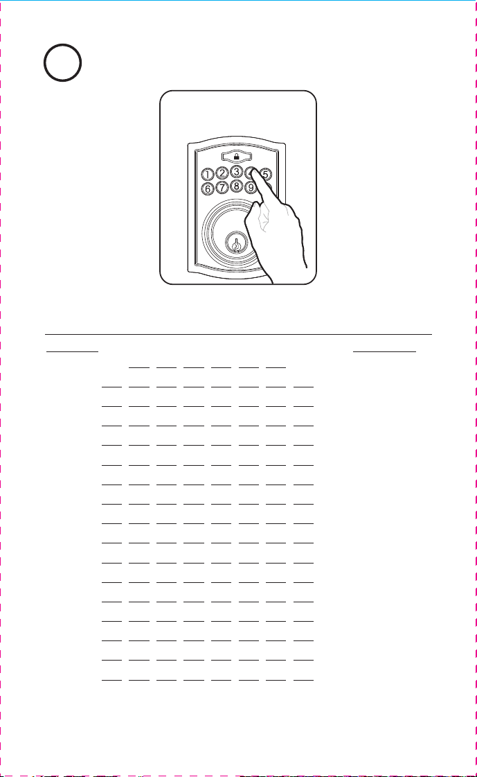
Unlocking Door with User Code
3
Enter User Code
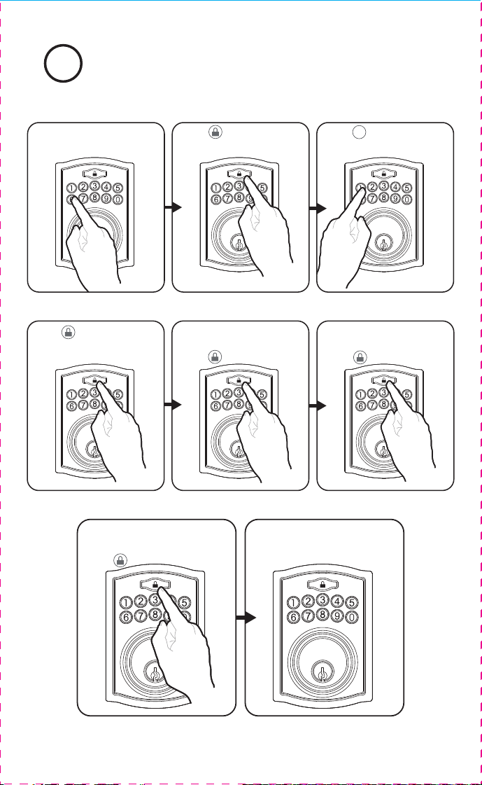
Deleting a User Code4
Repeat the User #
Press
Green light flashes
confirming success
Input Admin code
Press
Press Press
2
Input existing user #
between 01-50
Press
Deleting All User Codes
Reenter Admin code
Press Press
3
Press
Green light flashes
confirming success
Input Admin code
Press
5
DISABLE:
To disable the Vacation Mode, you must press and hold for more than 3 seconds,
then input followed by to unlock the door. Vacation Mode is now disabled.
AC
Hear 2 beeps light will illuminate red the door will lock
If the Lock is in the UNLOCK position.
10 1
AC
(Hear 1 beep)
ENABLE:
If the Door is in the LOCK position
Hear 1 beep and Light Indicator illuminates green then lock door
10
AC
Lock - Lock the door
Clear- Clear wrong keypad entries
Programming - Used in programming steps
Lock Button
M1741018, 1741020 E V0
Contact Us First! Do Not Return to Store
Don’t forget to register your lock at Truboltlocks.info for updates.
EMAIL: [email protected]
WEBSITE: www.truboltlocks.info
ADDRESS: Consumer Assistance Dept.
Lewis Hyman, Inc.
860 East Sandhill Avenue
Carson, CA 90746 USA
TELEPHONE: US/Canada 800-860-1677 Ext. 1801 (Toll Free)
Programming Instructions
Complete all the programming steps in the
programming mode within 5 seconds
Do not press keypad until keypad stops illuminating
To reset the lock to the original factory settings including the
Programming Code and all User Codes follow these steps:
1. Remove one battery for 10 seconds.
2. Reinsert the battery and wait for a long and short beep
3. Press 3 times within 3 seconds.
4. The lock will beep and the light indicator will turn green.
Restore Factory Settings
Low Battery Warning
Beeps and LED flashes red for 5 seconds. Replace with good
quality alkaline batteries.
Note: Removing batteries does not erase active Administrator
or User Codes.
Unlock / Valid programming: 1 long beep and LED illuminates green
Lock: 2 short beeps and LED illuminates red
2 short beeps and LED flashes red twiceInvalid Programming:
Low Voltage: Beeps for 5 seconds
3 long beeps LED flashes red three times
2 short beeps three times LED flashes red six times
Super Low Voltage:
4 Incorrect code entry attempts: 2 short beeps and LED illuminates red each attempt
Power on: 1 long beep and 1 short beep and LED illuminates green
Chip Reset:
Lock Error:
Repeat operation after Lock Error:
Consumer Friendly Message Guide
4 short beeps and LED flashes red four times
1 long beep and 1 short beep and LED illuminates green
(may occur several times or once in a while)
You can “mute” or turn the “sound on” on your lock by entering the following.
(Factory setting is sound on).
Sound On (1) - Hear 1 beep and Light Indicator illuminates green.
Sound Off (2) - Hear 1 beep and Light Indicator illuminates green.
6
1 or 2
SOUND ON AND OFF
AC
1 = Sound On
2 = Sound Off
7
Additional Programming Functions
6
Additional Programming Functions
Lock / Clear / Programming
Administrator Code
AC
With Vacation Mode enabled, the system enters into low-power consumption mode. During this mode, all
buttons and functions will be disabled until they are re-enabled (see steps below).
After inputting the correct code the
door will unlock immediately
Programming Symbols
Vacation Mode
SET OR CANCEL AUTO LOCK
You can set the lock to automatically close after each time the lock is opened. Time
value range = 20 - 900 seconds, enter the following:
Set Auto Lock:
Hear 1 beep and Light Indicator illuminates green.Hear 1 beep and Light Indicator illuminates green.
To cancel Auto Lock set the time to 00, enter the following:
Cancel Time Value Auto Lock:
Hear 1 beep and Light Indicator illuminates green.
55
5
Automatic Lock Function
TEMPORARILY DISABLE:
While in Auto-Lock mode, unlock door using , within 10 seconds you must turn the
locking knob by hand to the locked position, wait more than 2 seconds then turn the
locking knob back to the unlock position. The Auto-Lock mode is now disabled.
RESTORE:
To restore the Auto-Lock function, turn the locking knob by hand to the locked position,
wait more than 2 seconds or press the Lock button on the keypad.
AC
AC
AC
00
Time Value
NOTE: If you only press the for more than 3 seconds but do not input ,
the system will remain in Vacation Mode.
Secure Lock-out period
Warning sounds and LED flashes red after 4 incorrect code attempts: Keypad shuts
down for 60 seconds.
AC
Troubleshooting Warranty
Issue Solution
Latch Working
Backwards-
Lock unlocks when
lock button is pushed
or locks when unlock
button or code is
pushed
Direction switch is set to incorrect setting.
• Remove the Interior Assembly and move the switch to the opposite
direction on the rear of the assembly.
• Check that your switch is set in the correct position Left or Right
Handed door.
If Correct
• Rotate Interior Knob and reinstall Interior Assembly. Retest again
while holding Interior Assembly in place.
Interior Knob will not
turn
Knob or vertical tailpiece is installed in incorrect position.
• Remove Interior Assembly and reposition the Interior Knob. With the
Deadbolt Latch retracted verify that the tailpiece is vertical.
Lock will not function
electronically
• Check that all batteries are fresh high quality Alkaline Batteries.
• Check for proper polarity (+ -) of all batteries.
• Check that the Control Wire is attached to the Interior Assembly
and not damaged.
• Check each wire for loose or disconnected wires.
• Disconnect the wiring harness and reconnect the wiring harness.
Lock gives error signal
when opening or
locking and Deadbolt
Latch will not extend
or retract completely
when door is closed
• Unlock door using Key or Interior Knob. While door is open, check that the Deadbolt
Latch operates smoothly.
• Check for proper alignment of the strike plate, adjust as needed to assure there is
no binding against the Deadbolt Latch.
• Make sure tail piece is in the vertical position and straight up and down.
Deadbolt Latch is
sticking
Installation screws of the lock may be too tight and have to be loosened.
• Remove Interior Assembly.
• Slightly loosen the Mounting Plate screws.
• Lock and unlock using the Key.
• Reattach Control Wire and Interior Assembly.
Keypad not working
• Wait 60 seconds, keypad may be locked out due to incorrect code.
• Replace with 4 high quality alkaline batteries.
Keypad beeps and
LED flashes
• Replace with 4 high quality alkaline batteries.
DO NOT RETURN TO STORE!
If any parts are missing or damaged, please call Customer Service
Toll free at 1-800-860-1677 (Toll Free, M-F 7am – 5pm PST).
Online installation videos can be viewed at TruBoltLocks.info.
Don’t forget to register your lock at TruBoltLocks.info for updates.
Limited 1-Year Electronic Warranty
Limited Lifetime Mechanical and Finish Warranty
This Tru-Bolt® product comes with a 1-Year Limited Warranty on Electronic
Parts and a Limited Lifetime Mechanical and Finish Warranty against defects
in materials and workmanship under normal use to the original residential
user. Proof of purchase and ownership is required for the warranty to be in eect.
This warranty is non transferable and applies to the original purchaser
only, as long as the original purchaser occupies the residential premises upon
which the product[s] was originally installed. This warranty DOES NOT
COVER removal and reinstallation of product[s], scratches, abrasions,
deterioration due to the use of paints, solvents or other chemicals, abuse,
misuse, or product[s] used in commercial applications, does not cover any
losses, injuries to persons/property or costs, and shipping and freight
expenses required to return product[s]. In no event shall Tru-Bolt® be liable
for any special, incidental or consequential d
amages. If this product[s] is
considered a consumer product, please be advised that some local and state
laws do not allow limitations on incidental or consequential damages or how
long an implied warranty lasts, so that the above limitations may not fully apply.
Refer to your local laws for your specific rights under this warranty. If
there are any problems please call our customer service with any questions or
concerns.
Creating Administrator Code11
Input 6 digit code
Press
Press Press
4
Repeat the 6 digit code
Press
Green light flashes
confirming success
Input Admin code
(default 123456)
Press
Adding a User Code2
Input Admin code
Press
Press
1
Green light flashes
confirming success
Repeat 4-8 digit
user code
Press
Press
Input new 4-8 digit
user code
Press
Input user number
between 01-50
Press
User Code 13 (4-8 digits) / /
User Code 14 (4-8 digits) / /
User Code 15 (4-8 digits) / /
User Code 16 (4-8 digits) / /
User Code 17 (4-8 digits) / /
User Code 18 (4-8 digits) / /
My Codes: Date Created
Programming Code
(6 digits) / /
User Code 02 (4-8 digits) / /
User Code 03 (4-8 digits) / /
User Code 04 (4-8 digits) / /
User Code 05 (4-8 digits) / /
User Code 06 (4-8 digits) / /
User Code 07 (4-8 digits) / /
User Code 09 (4-8 digits) / /
User Code 10 (4-8 digits) / /
User Code 11 (4-8 digits) / /
User Code 12 (4-8 digits) / /
PROGRAMMING RECORD
Unlocking Door with User Code
3
Enter User Code
Deleting a User Code4
Repeat the User #
Press
Green light flashes
confirming success
Input Admin code
Press
Press Press
2
Input existing user #
between 01-50
Press
Deleting All User Codes
Reenter Admin code
Press Press
3
Press
Green light flashes
confirming success
Input Admin code
Press
5
DISABLE:
To disable the Vacation Mode, you must press and hold for more than 3 seconds,
then input followed by to unlock the door. Vacation Mode is now disabled.
AC
Hear 2 beeps light will illuminate red the door will lock
If the Lock is in the UNLOCK position.
10 1
AC
(Hear 1 beep)
ENABLE:
If the Door is in the LOCK position
Hear 1 beep and Light Indicator illuminates green then lock door
10
AC
Lock - Lock the door
Clear- Clear wrong keypad entries
Programming - Used in programming steps
Lock Button
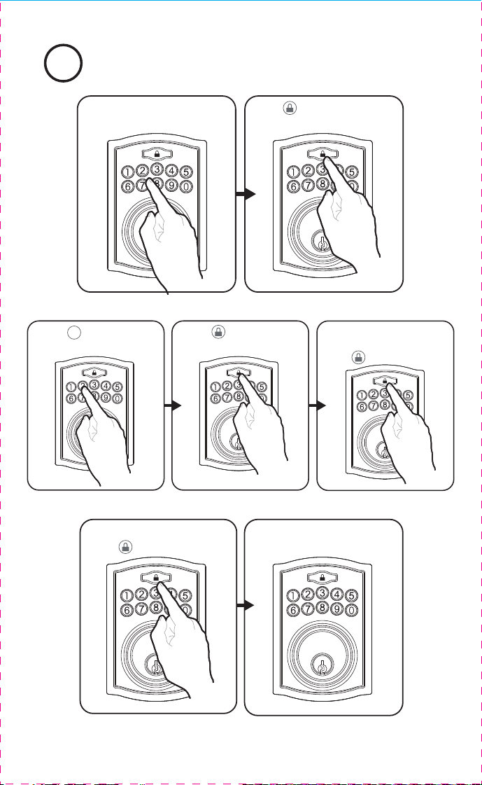
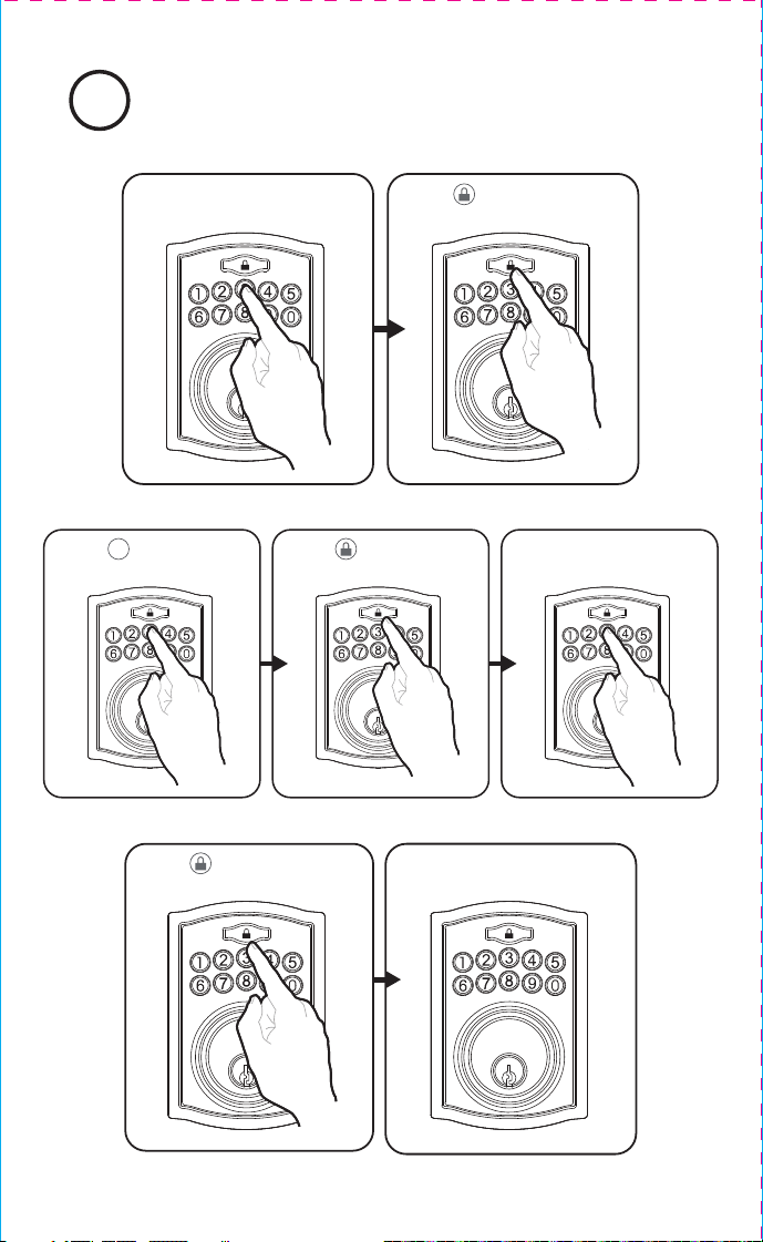
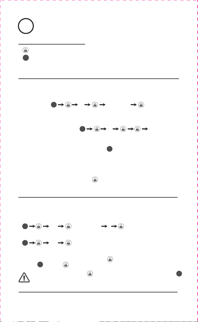
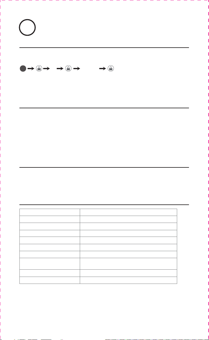
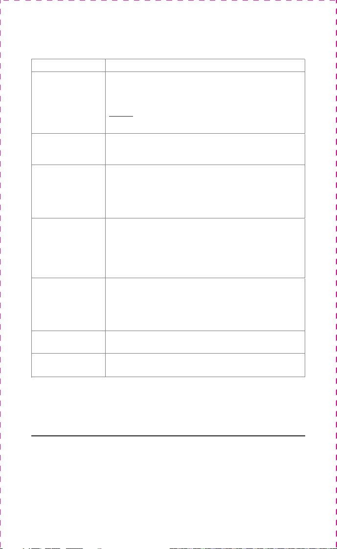