Documents: Go to download!
User Manual
- User Manual - (English)
- Technical Specifications - (English)
- Warranty - (English)

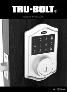
User manual Security Locks for Tru-Bolt 1740038
Contents
- Installation Instructions
- Package Contents / Tools Required
- Prepare Door And Jamb
- Adjusting Deadbolt Latch Set
- Installing Deadbolt Latch Set
- Preparing Interior Assembly
- Installing Exterior Assembly
- Installing Interior Assembly
- Operation Instructions
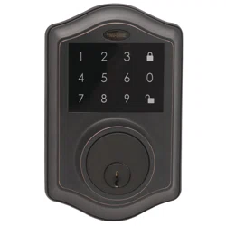
- Exterior Assembly Overview
- Locking And Unlocking / Changing Programming Code /
- Adding User Codes
- Deleting User Codes / Automatic Lock Function /
- Temporarily Disable Auto Lock
- Remote Control Set-Up And Operation
- Vacation Mode / Sound On And Off / Secure Lock-Out Period
- Restore Factory Settings / Low Battery Warning /
- Consumer Friendly Message Guide
- Installation Trouble Shooting
- Consumer Assistance
- Template
- Programming Record
- Limited Warranty
Installing Deadbolt Latch Set
- Insert Deadbolt Latch Set into door edge hole with the word “UP” and the arrow on the extension plate facing UP. Cross shaped spindle connector will be at the bottom of the Deadbolt Latch Set.
- Make sure the face plate sits flush with the door. Do not force the latch into the mortise flush. Chisel out excess material if necessary for a flush fit.
- Using two 3/4” (19mm). screws provided, screw the latch into the door with a hand held screwdriver. DO NOT OVER TIGHTEN.
NOTE: Deadbolt Latch must be retracted when installing
Installing Exterior Assembly
Work with the Door Open for easy access.
- Unpack the Exterior Assembly. Use care to not scratch the green circuit board during handling and installation.
- Check that the Rubber Gasket is properly seated on the Exterior Assembly.
- Insert the Exterior Assembly onto the door with the tailpiece going through the Deadbolt Latch Set cross shaped spindle connector in the VERTICAL POSITION. Route the Control Wire through the door over the Deadbolt Latch Set.
Installing Batteries
- Insert 4 AA high quality Alkaline batteries into the Battery Compartment in the direction noted +/- on the Compartment. The Lock will beep 2 times, the keypad will illuminate blue, and the Light Indicator will flash green twice to signify that it has received power (Figure 13a).
- Slide the Battery Cover down into the track on the Interior Assembly to cover the batteries (Figure 13b).
Installation Trouble Shooting
Latch Working BackwardsLock unlocks when lock button is pushed or locks when unlock button or code is pushed
- Direction switch is set to incorrect setting. Remove the Interior Assembly and move the switch to the opposite direction. Check that your switch is set in the correct position Left or Right Handed door.
- If Correct: Rotate Interior Knob and reinstall Interior Assembly. Retest again while holding Interior Assembly in place.
Interior Knob will not turn.
- Knob or vertical tailpiece is installed in incorrect position. Remove Interior Assembly and reposition the Interior Knob. With the Deadbolt Latch retracted verify that the tailpiece is vertical.
Lock will not function electronically.
- Check that all batteries are fresh high-quality Alkaline Batteries.
- Check for proper polarity (+ -) of all batteries.
- Check that the Control Wire is attached to the Interior Assembly.
Lock gives error signal when opening or locking and Deadbolt Latch will not extend or retract completely when door is closed.
- Unlock door using Key or Interior Knob. While door is open, check that the Deadbolt Latch operates smoothly. Check for proper alignment of the strike plate, adjust as needed to assure there is no binding against the Deadbolt Latch.
Deadbolt Latch is sticking - Installation screws of the lock may be too tight and have to be loosened.
- Remove Interior Assembly.
- Slightly loosen the Mounting Plate screws.
- Lock and unlock using the Key.
- Reattach Control Wire and Interior Assembly.
See other models: 1740006 1740016 1742002 1740128 1740118

