2-3/4" (70 mm)2-3/8" (60 mm)
180°
70 mm
60 mm
b
a
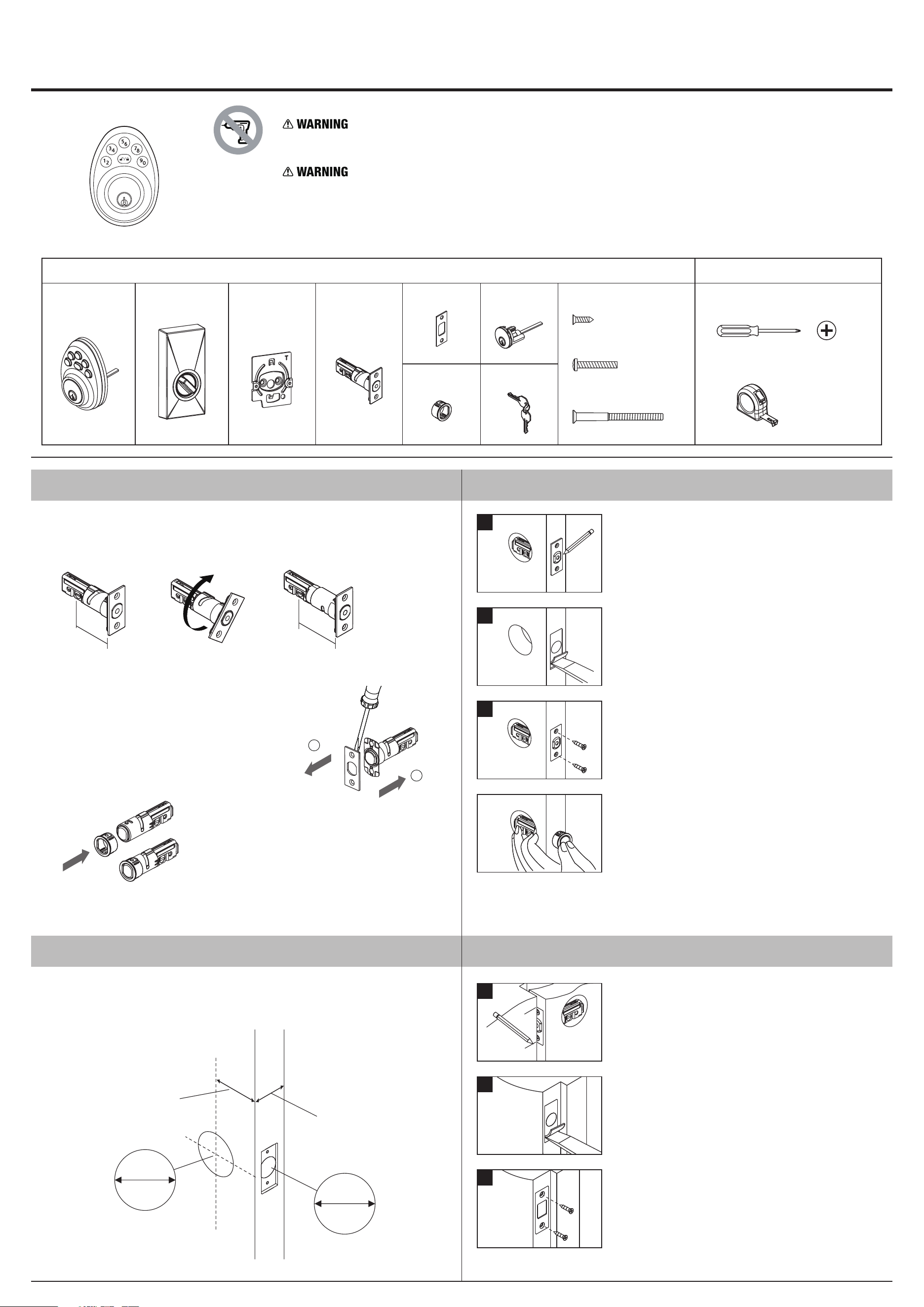
LATCH ADJUSTMENT
Determine if the latch needs to be adjusted to the2-3/4" (70 mm) backset.
To adjust, rotate the latch until it stops.
Reverse the direction to return to the 2-3/8" (60 mm) backset.
Determine which latch mounting method will be used
and make necessary adjustments.
No adjustment required for square latch face plate.
a. Use a flat screwdriver to separate the face plate.
b. Snap selected latch face onto back plate.
Remove original latch faceplate.
Align the as illustrated and snap
into the latch case.
drive-in sleeve
Drive-in Latch
Change Latch Face
PACKAGE CONTENTS
Mounting Plate
TOOLS NEEDED (NOT INCLUDED)
Keys
Wood Screws Qty. 4
Mounting Screws Qty. 2
Phillips Screwdriver
Tape Measure
Strike Plate
Latch
Mounting Screws Qty. 2
Cylinder
Do not use an electric screwdriver during installation.
This Manufacturer advises that no lock can provide complete security by itself.
This lock may be defeated by forcible or technical means, or evaded by entry elsewhere on the property.
No lock can substitute for caution, awareness of your environment, and common sense.
Builder's hardware is available in multiple performance grades to suit the application.
In order to enhance security and reduce risk, you should consult a qualified locksmith or other security professional.
PZU-INS-EN
Exterior Assembly Interior Assembly
PZU-INS-EN
Drive-in Installation
1. PREPARE DOOR AND CHECK DIMENSIONS
Use template enclosed to mark holes on door face.
Drill 2-1/8" (54 mm) holes from both sides of door.
Drill 1" (25.4 mm) holes in door edge for latches.
2. INSTALL LATCH
3. INSTALL STRIKE
a. Close the door so the latchbolt is against the door frame.
Mark the centre line on the doorframe exactly opposite
the latch hole in the door edge.
b. Measure one half of door thickness from door stop and
vertically mark center line of strike.
Drill 1" (25.4 mm) hole, 1" (25.4 mm) deep at intersection
of horizontal and vertical line of strike. Mark outline using
strike plate and chisel 5/64" (2 mm) deep for strike.
c. Install strike and tighten screws.
1-3/8"-1-3/4"
(35 mm-45 mm)
1"
25.4 mm
2-1/8"
54 mm
backset
2-3/8" (60 mm)
or
2-3/4" (70 mm)
a. Insert latch in hole and keep it parallel to door face.
Mark outline of face plate and remove latch.
b. Chisel 5/32" (4 mm) deep inside traced outline or until
face plate is flush with door edge.
c. Insert latch and tighten screw.
a
b
c
a
b
c
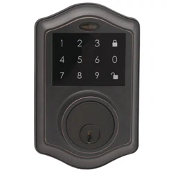
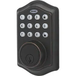
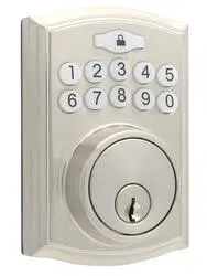
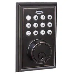
ELECTRONIC DEADBOLT INSTALLATION INSTRUCTIONS
Install Drive-in Latch
Drive the latch into the hole on edge of door.
Drive-in
(Optional)

Pass the IC wire under the latch to the interior side of the door.
Install cylinder into the deadbolt keypad assembly with tailpiece in horizontal position
inserted through hub of the latch.
Face the door from the outside.
The door is left-handed if the hinges are on the left side of the door,
whereas the door is right-handed if the hinges are on the right side of the door.
Put the harness through the right side of the wire hole on the mounting plate.
Fix the mounting plate with screws.
If outside lock assembly is lopsided, please loosen
the screws to adjust its position and tighten the screws again.
NOTE: Please make sure the harness pass through
the right side of the wire hole which on the
bottom of the mounting plate.
5. INSTALL INSIDE MOUNTING PLATE
8. INSTALL INTERIOR ASSEMBLY
Rotate the thumb turn piece to the LEFT at 45 degrees for right-handed doors.
Rotate the thumb turn piece to the RIGHT at 45 degrees for left-handed doors.
For right-handed door
For left-handed door
TEMPLATE
45mm 40mm 35mm
1-3/4" 1-9/16" 1-3/8"
Fit here on door edge
FOR BACKSET 70 mm)2-3/4" (
FOR BACKSET 60 mm)2-3/8" (
Mark Ø1" (25.4 mm) hole at centr
of door edge.
e
Ø ( )2-1/8" 54 mm
51mm
2"
4. INSTALL KEYPAD ASSEMBLY
6. IDENTIFY DOOR HANDING
7. ADJUST THUMB TURN PIECE
Connect the inner and outer harness connectors.
Insert 4 (AA) 1.5 V Alkaline batteries and cover the battery lid.
Remarks: Alkaline batteries are recommended in order to stabilize the
power supply.
If you don't use Alkaline, battery performance will be reduced greatly.
Ensure that the deadbolt tailpiece is engaged with turn piece and the
connector is plugged into the door hole, then attach interior assembly to the door
with screw.
NOTE: Before fixing the interior assembly with screw, please make sure the
connector is plugged into the door hole to avoid damage
caused by squeeze.
harness
harness
Please manually test to ensure that the turnpiece can rotate normally.
After the test, please return the turnpiece to unlock position.
Finally, please follow the below steps to set the door handing process.
unlock lock
IC wire
Programming Code (PC) : 0000
■ Door Handing Identification Process
Enter PC
Note : New installation or restoring default setting, you must run the door handing identification
process first.
Left-handed
Right-handed
Hinge Hinge
The lock needs to learn if your door is a right- or left-handed.handed
DO THIS FIRST
!