1
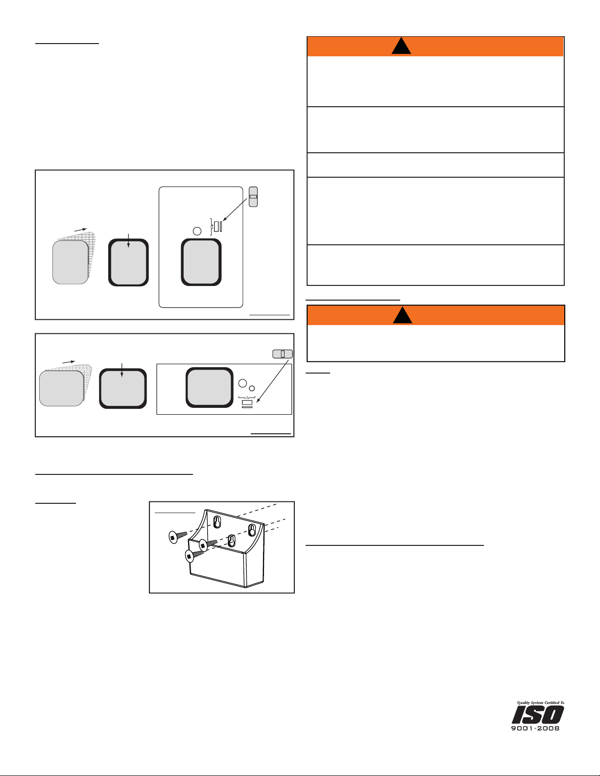
1. RECEIVER INSTALLATION
The receiver can be installed as either a wall mount
A
or a appliance mount
B
. Depending on your application, follow the applicable steps below after
having completed step 1.1.
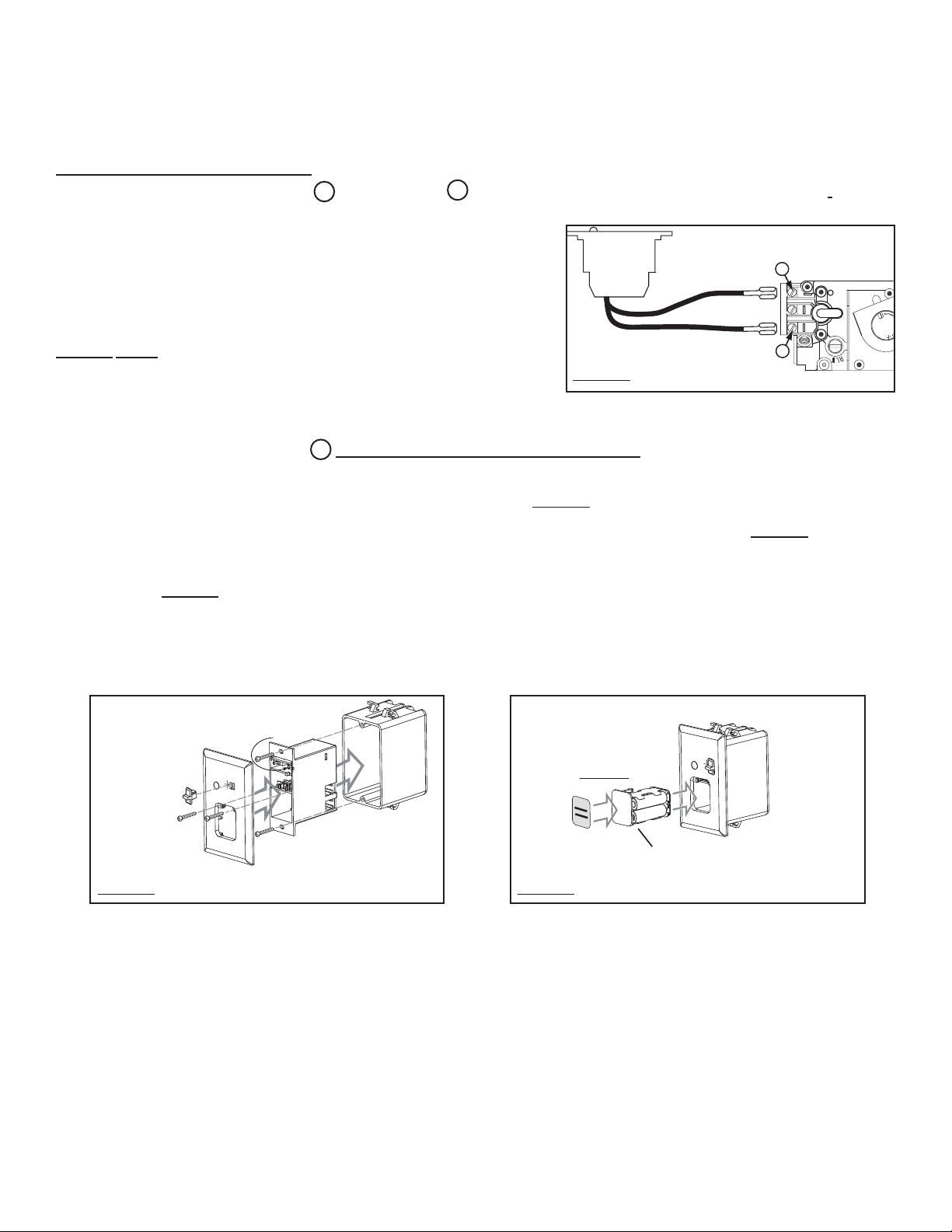
Turn off the electrical power and the gas supply to the appliance. Make sure the slide
switch on the receiver is set to the “OFF“ position.
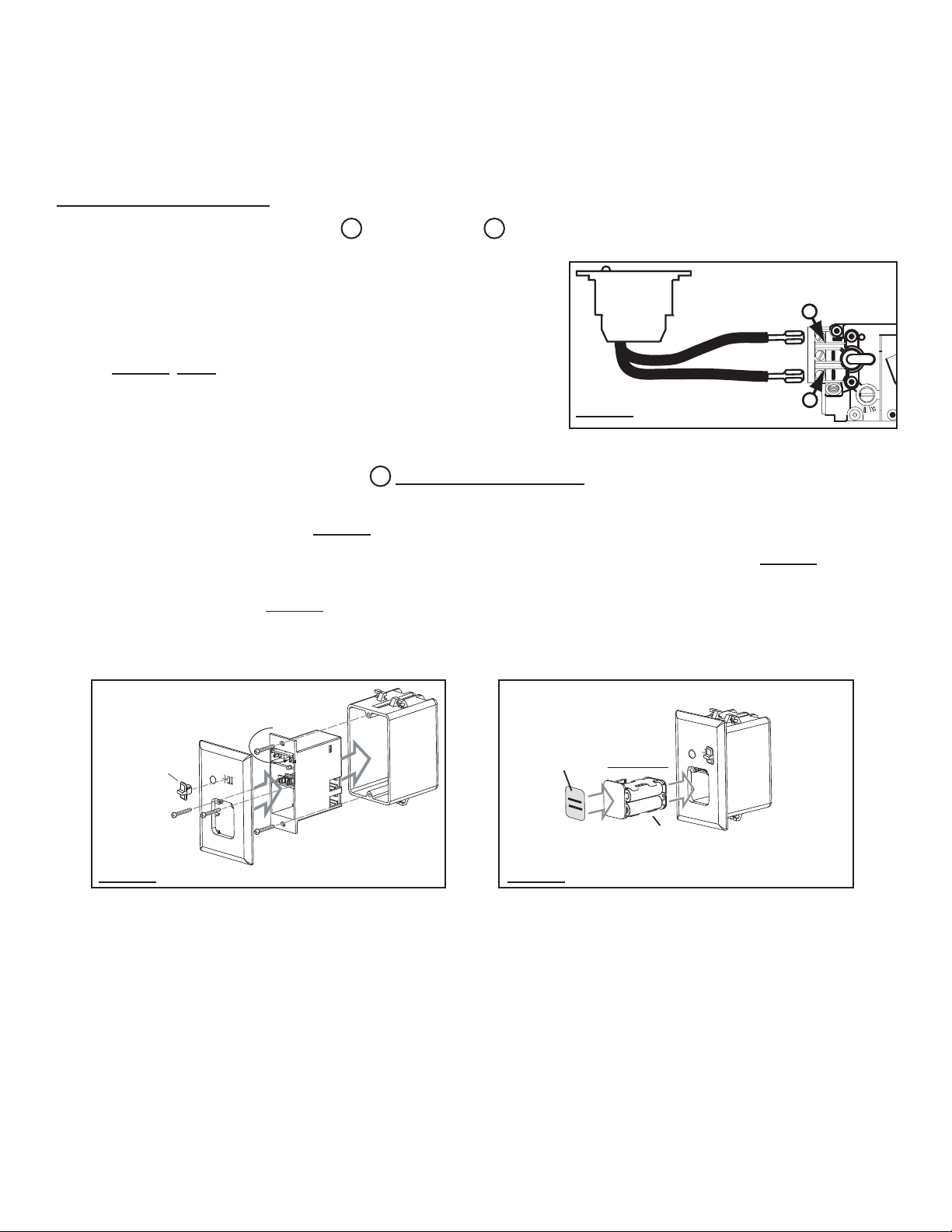
1.1 Either disconnect the existing switch wiring at the valve, or connect in parallel with any
other switch wiring at the valve. For millivolt switch wiring attach the wires to terminal 1
(marked TPTH) and terminal 3 (marked TH) of the gas valve from the output terminals on the
receiver. FIGURE 1 NOTE: If connecting the receiver to an appliance with electronic
ignition, connect the receiver wires to the two leads from the control module, identifi ed
as switch wires. (It may be necessary to remove the spade connectors and join the
wires using wire connectors)
A
RECEIVER WALL MOUNT
1.2 Press the battery compartment slightly into the receiver and release enabling the battery compartment to pop out. Pull off the slide switch. Slide the
receiver out of the appliance mounting plate. FIGURE 2
1.3 Using the screws provided secure the receiver to an existing junction box, then secure the wall face plate to the receiver. FIGURE 2
1.4 Replace the black slide switch with the white one included to match the cover plate. Place 4 AA batteries into the battery compartment and slide the
compartment back into the receiver. FIGURE 3
1.5 Turn on the electrical power and the gas supply to the appliance.
45 AND 60 UNIVERSAL REMOTE
INSTALLATION AND OPERATION
INSTRUCTIONS
P
I
PP
L
O
LL
T
OO
GAS VALVE
TP TH TP TH
RECEIVER
1
3
FIGURE 1
FIREPL
ACE
REM
OT
E
O
FF
O
N
R
E
MO
T
E
BAT.L
OW
JUNCTION
BOX
RECEIVER
SLIDE
SWITCH
WALL FACEPLATE
WALL MOUNT
INSTALLATION
FREQUENCY
ADJUSTMENT
SCREW
FIREPLA
C
EREM
O
TE
OF
F
ON
R
E
MO
TE
BA
T
.
L
O
W
BATTERY
COMPARTMENT
BATTERY
INSTALLATION
STICKER
(See 7. FINISHING)
FIGURE 2
FIGURE 3
2
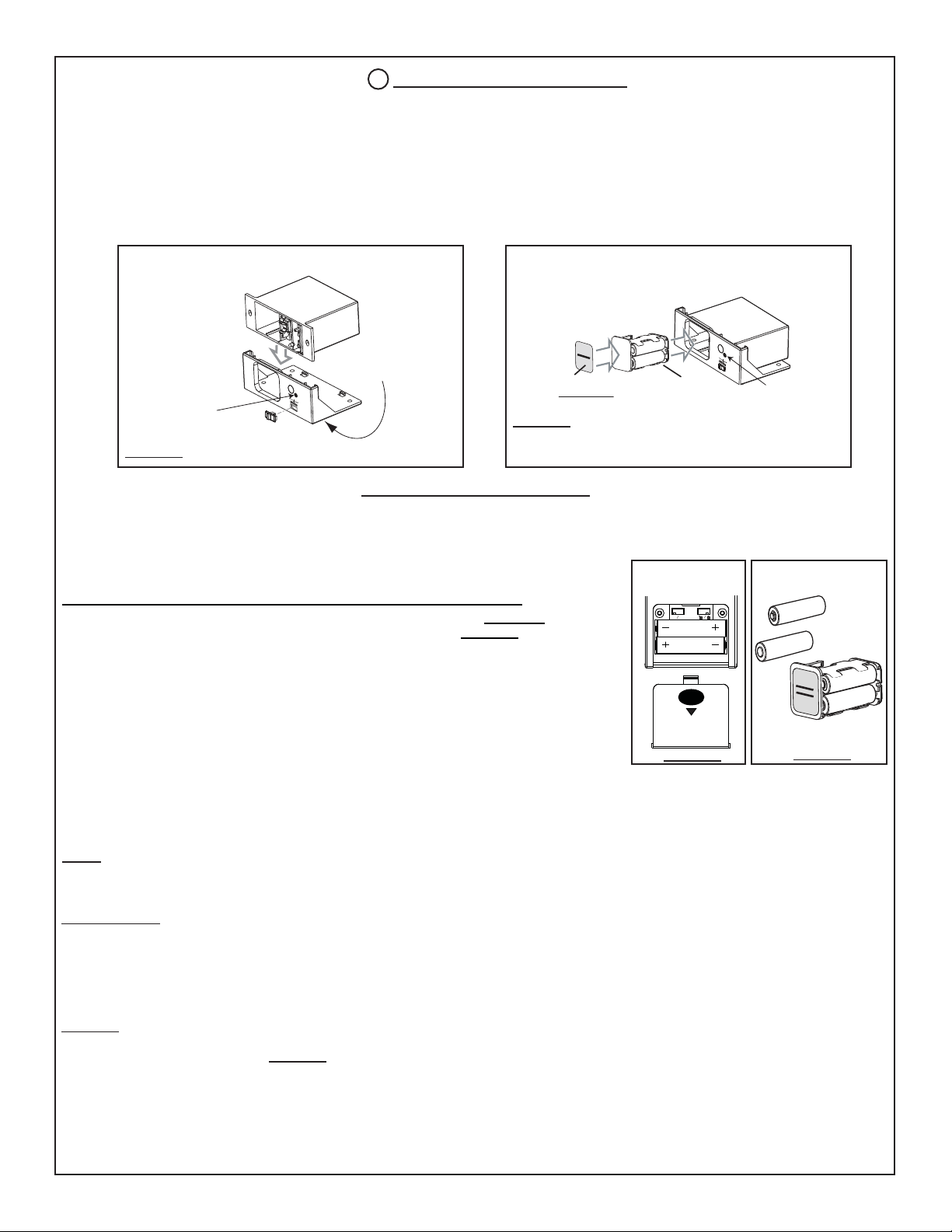
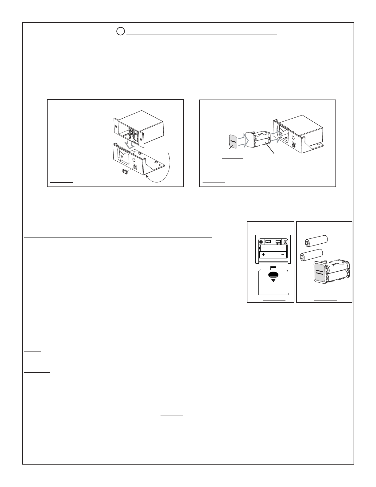
B
RECEIVER APPLIANCE MOUNT
For stove and insert models: Do not install the receiver in the gas control valve compartment in some models as this area becomes too hot. On stoves, it may
be installed in or behind the pedestal; on inserts, it may be installed behind the fl ashings or a similar convenient location.
In a zero clearance model: The receiver may be installed in the gas control compartment located below the fi rebox with the exception of clean-faced models
where access prohibits this location. See wall mount.
1.2 Ensuring that the mounting location will allow for the battery compartment to pop out, secure the receiver to an appropriate location depending on the
appliance model using the adhesive pad located on the bottom of the appliance mounting plate.
1.3 Turn on the electrical power and the gas supply to the appliance.
BAT
.
LOW
OFF
REMO
TE
O
N
APPLIANCE
MOUNTING PLATE
RECEIVER
SLIDE
SWITCH
APPLIANCE MOUNT
INSTALLATION
FREQUENCY
ADJUSTMENT
SCREW ACCESS
HOLE
ADHESIVE
PAD
BATTERY
INSTALLATION
BA
T
.LO
W
OFF
REMO
TE
O
N
BATTERY
COMPARTMENT
STICKER
(See 7. FINISHING)
FREQUENCY
ADJUSTMENT
SCREW ACCESS
HOLE
FIGURE 5
FIGURE 4
2. COMMUNICATION BETWEEN THE TRANSMITTER AND RECEIVER:
2.1 Place 2 “AAA” batteries into the battery compartment of the transmitter. FIGURE 6
2.2 Place 4 “AA” batteries into the battery compartment of the receiver. FIGURE 7
2.3 Slide the switch on the receiver to the “REMOTE” position. The low battery indicator on the
receiver will fl ash and the receiver will beep twice. The receiver is now ready to communicate with the
transmitter.
You only have 30 seconds after the receiver is put in the “REMOTE” position to capture the
code, which will be indicated by three beeps from the receiver.
2.4 Point the transmitter at the receiver, push and hold the “ON” button for 1 to 2 seconds to capture a
pre-determined code.
2.5 The low battery indicator on the receiver will fl ash and the receiver will beep three times to confi rm
synchronization with the transmitter. At this time the remote should be fully operational.
2.6 Troubleshooting
The transmitter display says “ON” but the appliance is not on. Turn the transmitter to “OFF” and then back to “ON”. Pushing the “ON” button too quickly
will not allow the receiver to pick up the signal from the transmitter. The transmitter button must be held for 1 to 2 seconds. If the remote still fails to
communicate with the receiver move closer to the receiver to ensure communication is not interrupted.
NOTE: To access the frequency adjustment screw in a wall mount installation, the wall face plate must be removed. The frequency adjustment screw
has been factory set. If for any reason the communication isn’t strong enough between the receiver and transmitter, you can turn the adjustment screw
counter-clockwise.to increase its strength or clockwise to decrease it. 1/4 turns are recommended.
AAA
AAA
BATTERY
COVER
TRANSMITTER
°F °C
+ AA
-
- AA +
+ AA -
- AA +
RECEIVER
FIGURE 7
FIGURE 6
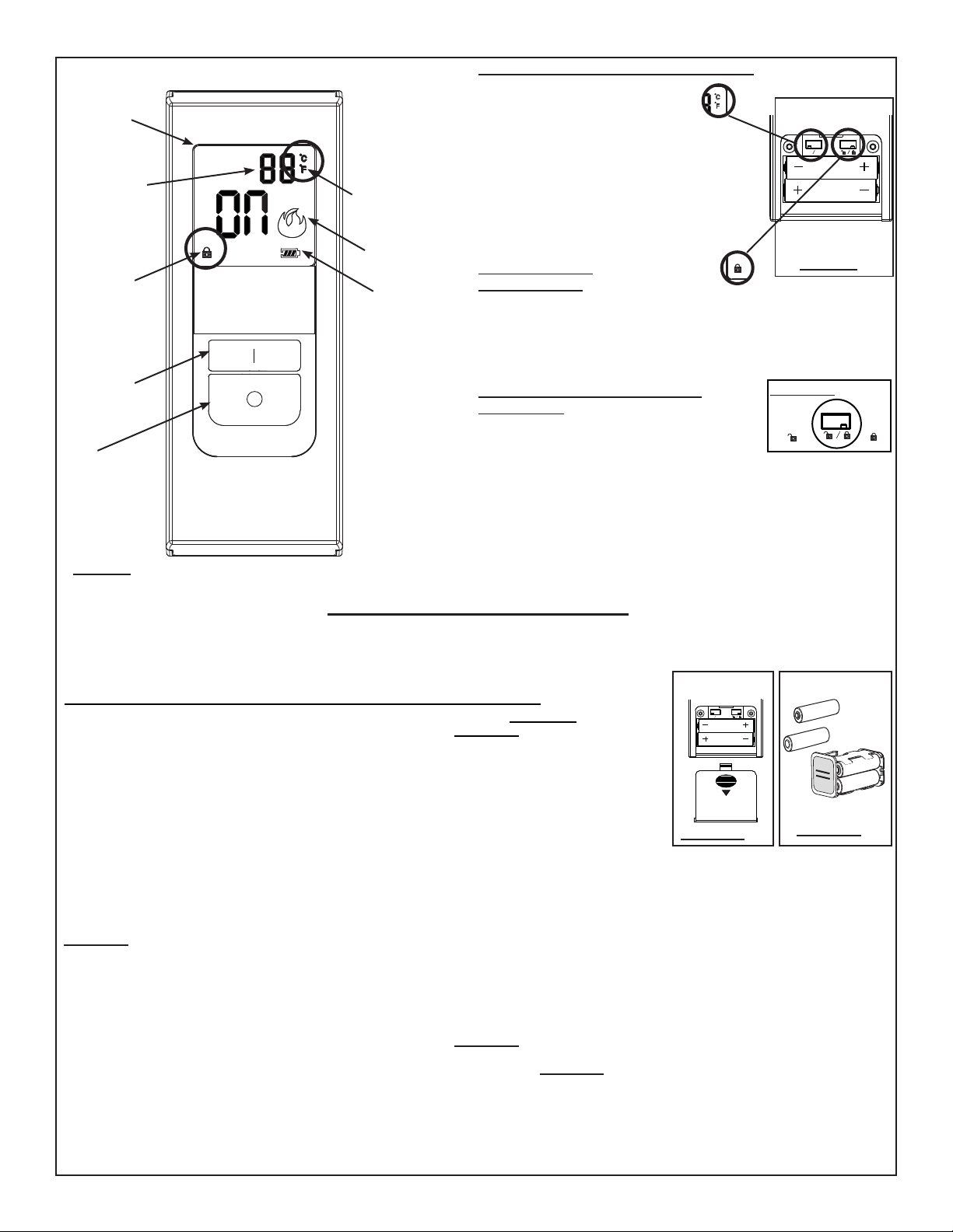
45 TRANSMITTER OPERATION
The 45 universal remote has been approved for use with most gas fi replaces, stoves, and inserts using a millivolt system or electronic ignition system.
The 45 provides on/off status, the current room temperature as well as having low battery indicator and child-proof features. The 45 allows you to switch
the appliance on or off from anywhere in the room.
This transmitter kit is tested and safe when installed in accordance with these instructions.
3. BATTERIES:
New batteries have a limited shelf life and depending upon their age, may need to be replaced after a short period of time. Batteries should be replaced
at least every 6 months or when the low battery indicator is lit on the receiver or the transmitter LCD. Use alkaline batteries only. Remember to change
the batteries in both the receiver and the transmitter.
3.1 TO CHANGE BATTERIES:
Receiver: Slide the switch to OFF. Press the battery compartment slightly into the receiver and release enabling the battery compartment to pop out.
After removing the original batteries, wait at least 1 minute before replacing with fresh batteries. (Follow the programming instructions previously stated)
FIGURE 7
Transmitter: Gently press and slide the battery cover from the rear surface of the transmitter. After removing the original batteries, wait at least 1 minute
before replacing with fresh batteries. FIGURE 6
3.2 IN THE EVENT OF A BATTERY FAILURE:
If the receiver batteries fail, the appliance will no longer turn on or off. To operate the appliance in the event of a battery failure, the slide switch located
on the receiver may be switched to the “ON” position to operate the appliance. (Section 1)
3
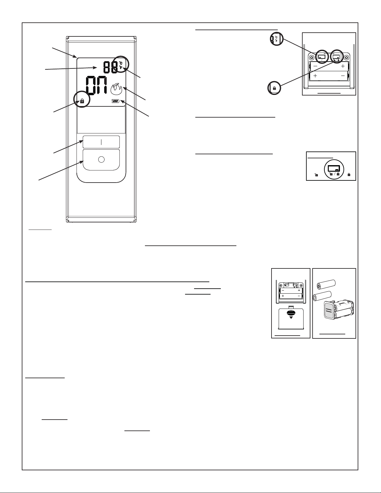
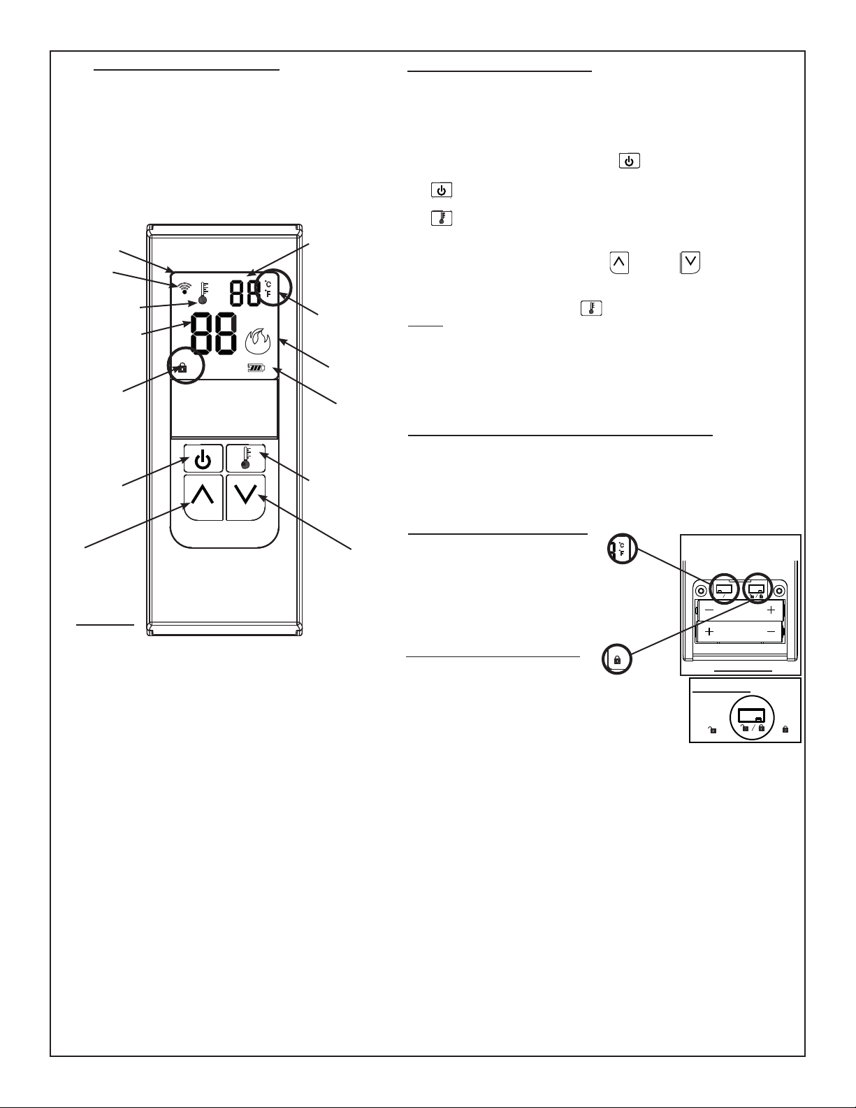
4. TRANSMITTER OPERATION:
The receiver switch must be
in the REMOTE position for
the transmitter to function.
This remote system operates
using radio frequency signals
sent by the transmitter to the
receiver. It is recommended
that the distance between the
transmitter and receiver never
exceeds 20’ and 10’ if the
receiver is located within the
fi rebox shell. Low batteries will
also affect operational distance.
5.
TEMPERATURE FUNCTION:
Remove the battery cover on the back of the transmitter to expose the
°C/°F dip switch. Move the dip switch to your desired temperature mode.
Selected temperature mode will appear in the top right corner beside the
room temperature.
6. CHILD-PROOF FUNCTION:
6.1 Remove the battery cover at the back of the
transmitter to expose the child-proof dip switch.
6.2 Slide the child-proof dip switch to the lock
position to activate the child-proof function. A lock
symbol will appear in the bottom left corner of the
transmitter display when the child-proof function is activated.
6.3 In child-proof mode the transmitter will not operate the receiver until
the switch is returned to the un-lock position however the receiver will
continue operate in the thermostatic mode when locked.
AAA
AAA
°F °C
TRANSMITTER
REAR VIEW
FIGURE 9
LOCK
UN-LOCK
FIGURE 10
LCD
DISPLAY
ON
BUTTON
OFF
BUTTON
FLAME
INDICATOR
LOW
BATTERY
INDICATOR
CHILD-PROOF
FUNCTION
INDICATOR
TEMPERATURE
INDICATOR
FIGURE 8
ROOM
TEMPERATURE
2. COMMUNICATION BETWEEN THE TRANSMITTER AND RECEIVER:
2.1 Place 2 “AAA” batteries into the battery compartment of the transmitter. FIGURE 11
2.2 Place 4 “AA” batteries into the battery compartment of the receiver. FIGURE 12
2.3 Slide the switch on the receiver to the “REMOTE” position. The low battery indicator on the receiver will
fl ash and the receiver will beep twice. The receiver is now ready to communicate with the transmitter.
2.4 Point the transmitter at the receiver, push and hold the “ON” button for 1 to 2 seconds to capture a pre-
determined code.
You only have 30 seconds after the receiver is put in the “REMOTE” position to capture the code,
which will be indicated by three beeps from the receiver.
2.5 The low battery indicator on the receiver will fl ash and the receiver will beep three times to confi rm
synchronization with the transmitter. At this time the remote should be fully operational.
2.6 TROUBLESHOOTING
The transmitter display says “ON” but the appliance is not on. Turn the transmitter to “OFF” and then back to “ON”. Pushing the “ON” button too
quickly will not allow the receiver to pick up the signal from the transmitter. The transmitter button must be held for 1 to 2 seconds. If the remote still
fails to communicate with the receiver move closer to the receiver to ensure communication is not interrupted.
AAA
AAA
BATTERY
COVER
TRANSMITTER
°F °C
+
AA -
- AA +
+ A
A
-
- A
A
+
RECEIVER
FIGURE 12
FIGURE 11
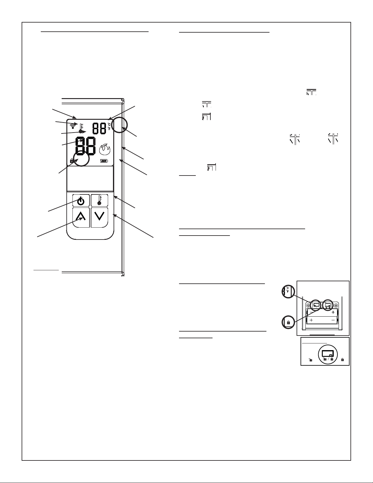
60 TRANSMITTER OPERATION
The 60 universal remote has been approved for use with most gas fi replaces, stoves, and inserts using a millivolt system or electronic ignition.
The 60 is a thermostatically controlled transmitter that provides on/off status, displays room/set temperature as well as having low battery indicator
and child-proof features.
This transmitter kit is tested and safe when installed in accordance with these instructions.
3. BATTERIES:
New batteries have a limited shelf life and depending upon their age, may need to be replaced after a short period of time. Batteries should be
replaced at least every 6 months or when the low battery indicator is lit on the receiver or the transmitter LCD. Use alkaline batteries only.
Remember to change the batteries in both the receiver and the transmitter.
3.1 TO CHANGE BATTERIES:
Receiver: Slide the switch to OFF. Press the battery compartment slightly into the receiver and release enabling the battery compartment to pop
out. After removing the original batteries, wait at least 1 minute before replacing with fresh batteries. (Follow the programming instructions previously
stated) FIGURE 12
Transmitter: Gently press and slide the battery cover from the rear surface of the transmitter. After removing the original batteries, wait at least 1
minute before replacing with fresh batteries. FIGURE 11
3.2 IN THE EVENT OF A BATTERY FAILURE:
If the receiver batteries fail, the appliance will no longer cycle on or off, remaining in the current operating mode. To operate the appliance in the event
of a battery failure, the slide switch located on the receiver may be switched to the “ON” position to operate the appliance. (Section 1)
3.3 If the transmitter batteries fail while in Thermostatic mode and there is no communication with the receiver, as a safety feature, the appliance will
shut down after 12 hours and not function until batteries are replaced.
45
4
5. THERMOSTATIC FUNCTION:
Thermostatic control automatically cycles the appliance on and off to maintain
the desired room temperature. When in thermostat mode, due to sensitive
temperature monitoring components in the transmitter, it is important not to
place the transmitter too close or too far from the appliance. Being too close
will cycle the appliance on and off frequently, while being too far away may
result in the appliance staying on for longer periods of time.
To turn the appliance burner on, press the
(ON/OFF) button. The LCD will
display the word “ON” and the fl ame indicator will be shaded in.
The
(ON/OFF) button is used to turn the appliance on or off only. It does
not set temperature.
The
(THERMOSTAT) button is used to control room temperature. Once
pushed, “ON” lights up next to the thermostat bulb located in the top left corner
of the LCD screen.
Set desired room temperature using the (UP) and (DOWN) buttons.
If the temperature of the room exceeds or falls below the desired room
temperature, the remote will automatically turn the appliance “OFF” or “ON”.
To turn off thermostat mode, press (THERMOSTAT) button again.
NOTE: To reduce battery consumption, room temperature updates are made
every 60 seconds.
When the transmitter batteries are exhausted or the transmitter is removed
from the vicinity of the fi replace, the communication link will be broken. When
in thermostatic mode, unless the batteries are replaced or the transmitter is
returned, the fi replace will be shut off after 12 hours as a safety feature.
6. THERMOSTATIC TEMPERATURE DIFFERENTIAL
In thermostatic mode there is a 1° temperature differential above and below
the set temperature. This helps to cut back on the number of operational
cycles. For example: if the set temperature is 20°, the appliance will turn on
until the room temperature is 21°, then back off until the room temperature
drops to 19°.
7.
TEMPERATURE FUNCTION:
Remove the battery cover on the back
of the transmitter to expose the °C/°F
dip switch. Move the dip switch to
your desired temperature mode.
Selected temperature mode will
appear in the top right corner beside
the room temperature.
8. CHILD-PROOF FUNCTION:
8.1 Remove the battery cover at the
back of the transmitter to expose the
child-proof dip switch.
8.2 Slide the child-proof dip switch to the lock position to
activate the child-proof function. A lock symbol will appear
in the bottom left corner of the transmitter display when the
child-proof function is activated.
8.3 In child-proof mode the transmitter will not operate the receiver until the
switch is returned to the un-lock position however the receiver will continue
operate in the thermostatic mode when locked.
AAA
AAA
°F °C
TRANSMITTER
REAR VIEW
FIGURE 14
LOCK
UN-LOCK
FIGURE 15
4. TRANSMITTER OPERATION:
The receiver switch must be in the REMOTE position for the
transmitter to function. This remote system operates using radio
frequency signals sent by the transmitter to the receiver. It is
recommended that the distance between the transmitter and
receiver never exceeds 20’ and 10’ if the receiver is located within
the fi replace’s outer or inner cavity surrounding an insert. Low
batteries will also affect operational distance.
ON
OFF
LCD
DISPLAY
ON / OFF
BUTTON
THERMOSTAT
BUTTON
UP
BUTTON
DOWN
BUTTON
FLAME
INDICATOR
LOW
BATTERY
INDICATOR
THERMOSTAT
BULB
SIGNAL
INDICATOR
CHILD-PROOF
FUNCTION
INDICATOR
TEMPERATURE
INDICATOR
FIGURE 13
THERMOSTAT
SET
TEMPERATURE
ROOM
TEMPERATURE
F60
5
CANADIAN EQUIPMENT REQUIREMENTS:
This digital apparatus does not exceed the (Class A / Class B)
limits for radio noise emissions from digital apparatus set out in
the Radio Interference Regulations of the Canadian Department of
Communication. This device complies with RSS-210 of Industry and
Science Canada. Operation is subject to the following two conditions:
(1) this device may not cause interference, and (2) this device must
accept any interference, including interference that may cause
undesired operation of the device.
W415-1026 / C / 07.05.12
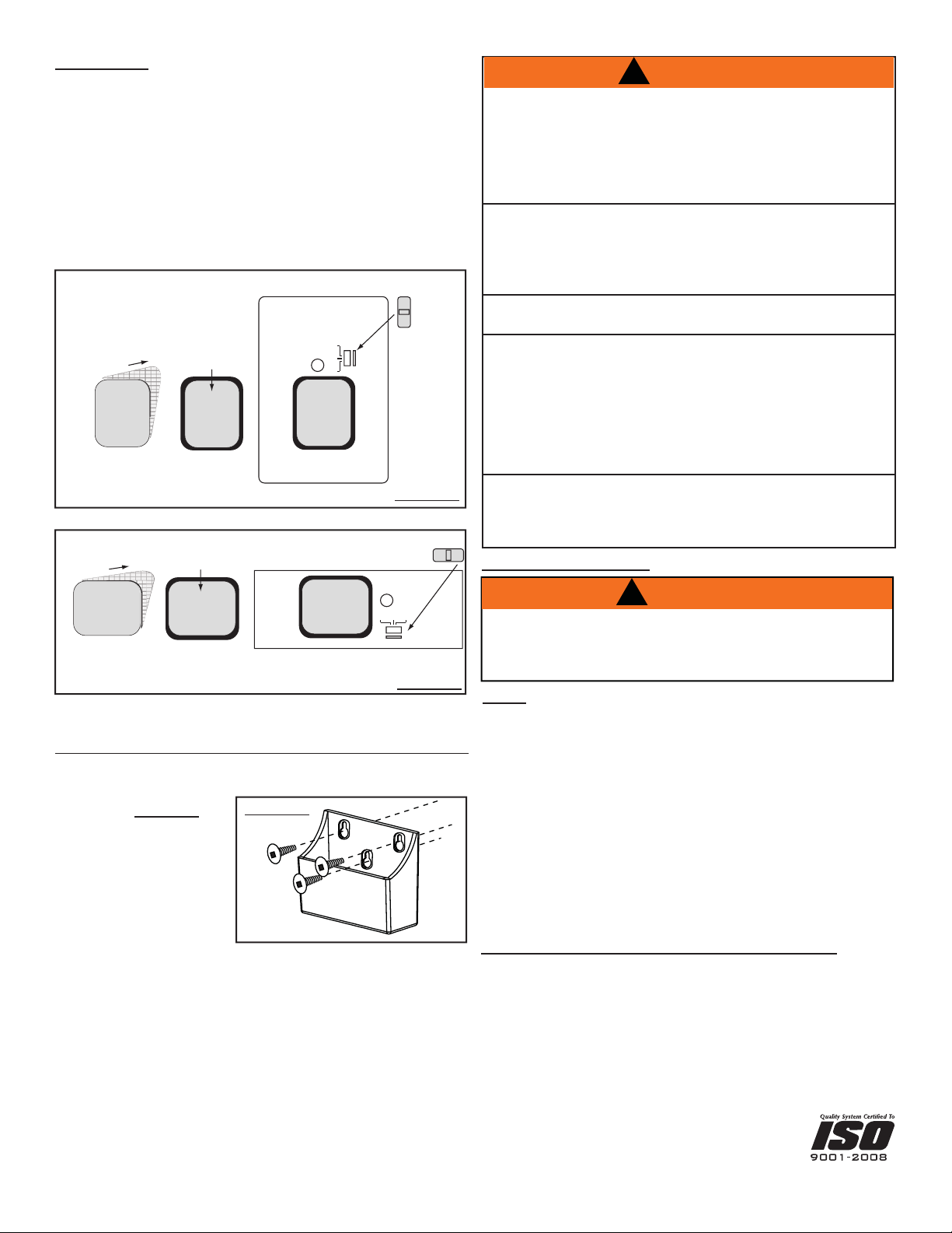
10. TRANSMITTER WALL MOUNT: (OPTIONAL)
Secure the wall cradle to the desired wall location using screws, and
anchors if required. If wall mount is not desired wall cradle can be discarded.
FIGURE 18
FIGURE 18
FCC REQUIREMENTS:
NOTE: This equipment has been tested and found to comply with the
limits for a Class B digital device, pursuant to Part 15 of the FCC Rules.
These limits are designed to provide reasonable protection against
harmful interference in a residential installation. This equipment
generates, uses and can radiate radio frequency energy and, if not
installed and used in accordance with the instructions, may cause
harmful interference to radio communications. However, there is no
guarantee that interference will not occur in a particular installation. If
this equipment does cause harmful interference to radio or television
reception, which can be determined by turning the equipment off and
on, the user is encouraged to try to correct the interference by one or
more of the following measures:
- Reorient or relocate the receiving antenna.
- Increase the separation between the equipment and receiver.
- Consult the dealer or an experienced radio TV technician for help.
!
WARNING
Changes or modifi cations to this unit not expressly approved by the
party responsible for compliance could void the user’s authority to
operate the equipment.
!
9. FINISHING:
Follow the diagram based on your receiver installation, wall mount or
fi replace mount.
Remove the battery compartment from the receiver by pressing and
releasing. Peel the self adhesive backing off the “PRESS TO OPEN”
sticker and affi x to the front surface of the battery compartment. Replace
the battery compartment into the receiver.
Secure the slide switch horizontally for the fi replace mounting plate and
vertically for the wall faceplate.
PRESS TO OPEN
AFFIX
BATTERY
COMPARTMENT
P
EE
L
STICKER
PRESS TO OPEN
PRESS TO OPEN
BAT.LOW
OFF REMOTE ON
FIREPLACE MOUNTING PLATE
SLIDE
SWITCH
RECEIVER FIREPLACE MOUNT
FIGURE 17
FIREPLACE REMOTE
ON
REMOTE
OFF
BAT.LOW
PRESS
TO OPEN
PEEL
PRESS
TO OPEN
AFFIX
BATTERY
COMPARTMENT
STICKER
PRESS
TO OPEN
WALL FACE PLATE
SLIDE
SWITCH
RECEIVER WALL MOUNT
FIGURE 16
ARNINGW
!
PROPERTY DAMAGE HAZARD.
EXCESSIVE HEAT CAN CAUSE PROPERTY DAMAGE.
The appliance can stay ignited for many hours. Take care to
turn off the appliance if it is unattended by an adult.
FIRE HAZARD. CAN CAUSE SEVERE INJURY OR DEATH.
The receiver causes the ignition of the appliance. The
appliance can turn on suddenly. Keep away from the burner,
especially when operating on the BACKUP switch.
Modifi cation of any part of this kit will void any warranty claims
and could create a fi re hazard.
The transmitter and the receiver are radio frequency
appliances. If the receiver is mounted inside metallic cases,
severe loss of performance (reduction of working range) may
result. When the receiver is installed inside the steel appliance
shell, it is recommended that the transmitter be located no more
than 10’ away for consistent operation.
In the event of prolonged absences, the appliance installed
with an 60 should not be left in thermostat mode or used as a
primary heat source. Use a wall thermostat if required.
Wolf Steel Ltd., 24 Napoleon Rd., Barrie, ON L4M 0G8 Canada • (705)721-1212 • fax (705)722-6031
1
INSTRUCTIONS D’INSTALLATION ET
D’OPÉRATION DES TÉLÉCOMMANDES
UNIVERSELLES 45, ET 60
P
I
PP
L
O
LL
T
OO
H
H
H
H
I
I
I
I
L
O
LL
SOUPAPE DE GAZ
TP TH TP TH
RÉCEPTEUR
1
3
FIGURE 1
FIREPL
ACE REM
OT
E
O
FF
O
N
REM
O
T
E
BAT.L
OW
BOÎTE DE
DÉRIVATION
RÉCEPTEUR
INTERRUPTEUR
PLAQUE MURALE
AVANT
INSTALLATION
AU MUR
RÉGLAGE DE LA
FRÉQUENCE
FIR
EPLA
CE
REMO
TE
OF
F
ON
R
EM
O
T
E
BA
T
.
L
O
W
COMPARTIMENT
À PILES
INSTALLATION
DES PILES
AUTOCOLLANT
(Voir 7. FINITION)
FIGURE 2 FIGURE 3
1. INSTALLATION DU RÉCEPTEUR
Le récepteur peut être installé soit sur le mur
A
, soit sur l’appareil
B
. Selon votre appareil, suivez les étapes appropriées cidessous après avoir
effectué l’étape 1.1.
Coupez l’alimentation électrique et en gaz à l’appareil. Assurez-vous que l’interrupteur
du récepteur est placé à « OFF ».
1.1 Déconnectez le branchement à distance de la soupape ou branchez en parallèle
avec tout autre branchement à distance de la soupape. Pour le branchement des fi ls de
l’interrupteur millivolt, reliez les fi ls des bornes de sortie du récepteur à la borne 1 (TPTH) et
à la borne 3 (TH) de la soupape de gaz.
FIGURE 1 NOTE : Si vous branchez le récepteur à un appareil possédant un système
d’allumage électronique, branchez les fi ls du récepteur aux deux fi ls du module de
contrôle, identifi és comme fi ls d’interrupteur. (Il pourrait être nécessaire d’enlever
les cosses et de raccorder les fi ls avec des connecteurs de fi l.)
A
INSTALLATION DU RÉCEPTEUR AU MUR
1.2 Appuyez légèrement sur le compartiment à piles du récepteur puis relâchez-le afi n de permettre au compartiment à piles de sortir.
Retirez l’interrupteur. Glissez le récepteur hors de la plaque de montage de l’appareil. FIGURE 2
1.3 À l’aide des vis fournies, fi xez le récepteur à une boîte de dérivation existante, puis fi xez la plaque murale à le récepteur. FIGURE 2
1.4 Remettez en place l’interrupteur noir avec l’interrupteur blancinclus afi n de correspondre à la plaque murale. Insérez quatre piles
« AA » dans le compartiment à piles, puis insérez le compartiment
dans le récepteur. FIGURE 3
1.5 Rétablissez l’alimentation électrique et en gaz à l’appareil.
2
B
INSTALLATION DU RÉCEPTEUR DANS L’APPAREIL
Pour les poêles et les encastrés : pour certains modèles, n’installez pas le récepteur dans le compartiment de la soupape de contrôle du gaz, car cet endroit
devient trop chaud. Sur les poêles, il peut être installé dans ou derrière le piédestal; sur les encastrés, il peut être installé derrière les contours ou à un endroit
pratique similaire.
Modèles à dégagement zéro : le récepteur peut être installé dans le compartiment de contrôle du gaz situé sous l’appareil à l’exception des modèles pleine
vision où l’accès à cet emplacement est interdit. Voir « Installation murale » (Figure 2).
1.2 En vous assurant qu’il y ait suffi samment d’espace pour permettre au compartiment à piles d’être retiré, fi xez le récepteur à un endroit approprié selon
le modèle de l’appareil à l’aide de la bande adhésive située en dessous de la plaque de montage de l’appareil.
1.3 Rétablissez l’alimentation électrique et en gaz à l’appareil.
BA
T.
LO
W
OFF
REMO
TE
O
N
PLAQUE DE MONTAGE
DE L’APPAREIL
INSTALLATION DANS
L’APPAREIL
RÉCEPTEUR
INTERRUPTEUR
BANDE
ADHÉSIVE
INSTALLATION
DES PILES
B
A
T
.
LO
W
O
FF
REMO
TE
O
N
COMPARTIMENT
À PILES
AUTOCOLLANT
(voir 7. FINITION)
FIGURE 5
FIGURE 4
2. COMMUNICATION ENTRE LA TÉLÉCOMMANDE ET LE RÉCEPTEUR :
2.1 Installez 2 piles « AAA » dans le compartiment à piles de la télécommande FIGURE 6
2.2 Installez 4 piles « AA » dans le compartiment à piles du récepteur. FIGURE 7
2.3 Placez le commutateur du récepteur à la position « REMOTE ». L’indicateur de piles faibles
du récepteur clignotera et le récepteur émettra deux bips pour signaler qu’il est maintenant prêt à
communiquer avec la télécommande.
Vous n’avez que 30 secondes après que le récepteur est à la position « REMOTE » pour capter
un code, qui sera indiqué par trois bips, émis par le récepteur.
2.4 Pointez la télécommande en direction du récepteur et appuyez sur le bouton « ON » pendant 1 à
2 secondes afi n d’obtenir le code préprogrammé.
2.5 L’indicateur de piles faibles du récepteur clignotera et le récepteur émettra trois bips afi n de
confi rmer la synchronisation avec la télécommande. La télécommande devrait être entièrement
fonctionnelle maintenant.
2.6 Dépannage
L’affi cheur de la télécommande indique « ON », mais l’appareil ne fonctionne pas. Éteignez la télécommande
en appuyant sur « OFF » et allumez-la de nouveau en appuyant sur « ON ». Le récepteur ne pourra pas capter le signal de la télécommande si le bouton
« ON » est enfoncé trop rapidement. Le bouton de la télécommande doit être enfoncé pendant 1 à 2 secondes. Si la télécommande est encore incapable
de communiquer avec le récepteur, rapprochez-la du récepteur pour assurer une communication ininterrompue..
NOTE : Pour accéder à la vis de réglage de la fréquence dans une installation murale, vous devez retirer la plaque murale. La vis de réglage de la
fréquence a été préréglée en usine. Si pour une raison quelconque la communication entre le récepteur et la télécommande n’est pas assez bonne, vous
pouvez tourner la vis de réglage vers la gauche pour augmenter le signal ou vers la droite pour le diminuer.
AAA
AAA
COUVERCLE
DES PILES
TÉLÉCOMMAND
E
°F °C
+ AA -
- AA +
+ A
A
-
- AA +
RÉCEPTEUR
FIGURE 7
FIGURE 6
OPÉRATION DE LA TÉLÉCOMMANDE F45
L’utilisation de la télécommande universelle 45 a été approuvée pour la plupart des foyers, poêles et encastrés au gaz utilisant un système
millivolt ou un système d’allumage électronique.
La 45 possède un bouton marche/arrêt, un indicateur de température ambiante de la pièce de même qu’un indicateur de piles faibles et une
fonction « sécurité pour enfants ». La 45 vous permet d’allumer ou d’éteindre l’appareil de n’importe quel endroit dans la pièce.
Ce système de télécommande est testé et certifi é sécuritaire lorsqu’il est installé selon ces instructions.
3. PILES :
Les nouvelles piles ont une durée de vie limitée, et selon leur âge, il se peut que vous deviez les remplacer après un court laps de temps. Les piles
devraient être remplacées tous les six mois ou lorsque l’indicateur de piles faibles est allumé sur le récepteur ou l’affi cheur de la télécommande.
N’utilisez que des piles alcalines. N’oubliez pas de changer les piles de la télécommande et du récepteur.
3.1 POUR CHANGER LES PILES :
Récepteur : placez l’interrupteur à « OFF ». Appuyez légèrement sur le compartiment à piles du récepteur, puis relâchez-le afi n de permettre au
compartiment à piles de sortir. Après avoir retiré les piles d’origine, attendez au moins une minute avant de mettre en place les nouvelles piles. (Suivez
les directives de programmation mentionnées précédemment) FIGURE 7
Télécommande : Appuyez légèrement sur le couvercle des piles et faites-le glisser depuis l’arrière de la télécommande. Après avoir retiré les piles
d’origine, attendez au moins une minute avant de mettre en place les nouvelles piles. FIGURE 6
3.2 EN CAS DE PANNE DE PILES :
Si les piles de la télécommande deviennent déchargées et qu’il n’y a plus de communication avec le récepteur, un dispositif de sécurité éteindra l’appareil
après 12 heures et celui-ci ne fonctionnera à nouveau que lorsque les piles seront remplacées.
3
4. OPÉRATION DE LA TÉLÉCOMMANDE :
L’interrupteur du récepteur doit être
en position REMOTE pour que la
télécommande fonctionne. Le système
de télécommande fonctionne par
radiofréquences qui sont envoyées par
la télécommande au récepteur. Il est
recommandé que la distance entre la
télécommande et le récepteur n’excède
jamais 20’ et 10’ si le récepteur est
situé dans le caisson de l’appareil. Des
piles faibles réduiront également la
distance de fonctionnement.
5.
FONCTION DE
TEMPÉRATURE
Retirez le couvercle des piles au dos de la télécommande afi n d’avoir
accès à l’interrupteur °C/°F.Placez l’interrupteur au mode désiré. Le mode
de
température choisi apparaîtra dans le coin supérieur droit, à côté de la
température de la pièce.
6. FONCTION « SÉCURITÉ POUR
ENFANTS » :
8.1 Retirez le couvercle de la télécommande afi n
d’exposer le
commutateur de SÉCURITÉ POUR ENFANTS.
8.2 Glissez le commutateur de SÉCURITÉ POUR ENFANTS à la position
de verrouillage afi n d’activer la fonction SÉCURITÉ POUR ENFANTS. Un
symbole de verrou apparaîtra dans le coin inférieur gauche de l’affi cheur de la
télécommande lorsque la fonction « SÉCURITÉ POUR ENFANTS »
est activée.
8.3 En mode SÉCURITÉ POUR ENFANTS, la télécommande ne pourra
pas faire fonctionner le récepteur jusqu’à ce que le commutateur soit remis
à sa position initiale. Toutefois, le récepteur continuera à fonctionner
en mode thermostatique lorsque verrouillé.
LOCK
UN-LOCK
FIGURE 10
AFFICHEUR
BOUTON
ON
BOUTON
OFF
INDICATEUR
DE FLAMME
INDICATEUR DE
PILES FAIBLES
INDICATEUR
DE FONCTION
« SÉCURITÉ
POUR
ENFANTS »
INDICATEUR DE
TEMPÉRATURE
FIGURE 8
TEMPÉRATURE
DE LA PIÈCE
2. COMMUNICATION ENTRE LA TÉLÉCOMMANDE ET LE RÉCEPTEUR :
2.1 Installez 2 piles « AAA » dans le compartiment à piles de la télécommande. FIGURE 11
2.2 Installez 4 piles « AA » dans le compartiment à piles du récepteur. FIGURE 12
2.3 Placez le commutateur du récepteur à la position « REMOTE ». L’indicateur de piles faibles du récepteur
clignotera et le récepteur émettra deux bips pour signaler qu’il est maintenant prêt à communiquer avec la
télécommande.
2.4 Pointez la télécommande en direction du récepteur et appuyez sur le bouton « ON » pendant 1 à 2
secondes afi n d’obtenir le code préprogrammé. Vous n’avez que 30 secondes après que le récepteur est
à la position « REMOTE » pour capter un code, qui sera indiqué par trois bips, émis par le récepteur.
2.5 L’indicateur de piles faibles du récepteur clignotera et le récepteur émettra trois bips afi n de confi rmer
la
synchronisation avec la télécommande. La télécommande devrait être entièrement fonctionnelle maintenant.
2.6 DÉPANNAGE
L’affi cheur de la télécommande indique « ON », mais l’appareil ne fonctionne pas. Éteignez la télécommande en appuyant sur « OFF » et allumezla
de nouveau en appuyant sur « ON ». Le récepteur ne pourra pas capter le signal de la télécommande si le bouton « ON » est enfoncé trop
rapidement. Le bouton de la télécommande doit être enfoncé pendant 1 à 2 secondes. Si la télécommande est encore incapable de communiquer
avec le récepteur, rapprochez-la du récepteur pour assurer une communication ininterrompue.
AAA
AAA
COUVERCLE
DES PILES
TÉLÉCOMMANDE
°F °C
+ AA -
-
AA +
+
AA -
-
AA
+
RÉCEPTEUR
FIGURE 12
FIGURE 11
OPÉRATION DE LA TÉLÉCOMMANDE 60
L’utilisation de la télécommande universelle 60 a été approuvée pour la plupart des foyers, poêles et encastrés au gaz utilisant un système millivolt
ou un système d’allumage électronique La 60 est une télécommande contrôlée par thermostat qui possède un bouton marche/arrêt, qui affi che la
température de la pièce/réglée et qui possède un indicateur de piles faibles et une fonction « sécurité pour enfants ».
Ce système de télécommande est testé et certifi é sécuritaire lorsqu’il est installé selon ces instructions.
3. PILES :
Les nouvelles piles ont une durée de vie limitée, et selon leur âge, il se peut que vous deviez les remplacer après un court laps de temps. Les piles
devraient être remplacées tous les six mois ou lorsque l’indicateur de piles faibles est allumé sur le récepteur ou l’affi cheur de la
télécommande. N’utilisez que des piles alcalines. N’oubliez pas de changer les piles de la télécommande et du récepteur.
3.1 POUR CHANGER LES PILES :
Récepteur : placez l’interrupteur à « OFF ». Appuyez légèrement sur le compartiment à piles du récepteur, puis relâchez-le afi n de permettre au
compartiment à piles de sortir. Après avoir retiré les piles d’origine, attendez au moins une minute avant de mettre en place les nouvelles piles.
(Suivez les directives de programmation mentionnées précédemment) FIGURE 12
Télécommande : Appuyez légèrement sur le couvercle des piles et faites-le glisser depuis l’arrière de la télécommande. Après avoir retiré les piles
d’origine, attendez au moins une minute avant de mettre en place les nouvelles piles. FIGURE 11
3.2 EN CAS DE PANNE DE PILES :
Si les piles du récepteur sont déchargées, l’appareil ne s’allumera ou ne s’éteindra plus, demeurant dans le mode de fonctionnement courant. Pour
faire fonctionner l’appareil pendant une panne de piles, l’interrupteur situé sur le récepteur peut être activé pour faire fonctionner l’appareil. (Section 1)
3.3 Si les piles de la télécommande deviennent déchargées et qu’il n’y a plus de communication avec le récepteur, un dispositif de sécurité éteindra
l’appareil après 12 heures et celui-ci ne fonctionnera à nouveau que lorsque les piles seront remplacées.
AAA
AAA
°F
°C
TÉLÉCOMMANDE
VUE ARRIÈRE
FIGURE 9
45
4
5. FONCTION THERMOSTATIQUE :
Le contrôle thermostatique allume et éteint l’appareil automatiquement pour
maintenir la pièce à la température désirée. Le contrôle thermostatique
allume et éteint l’appareil automatiquement pour maintenir la pièce à
la température désirée. En mode thermostat, il est important de ne pas
placer la télécommande trop près ou trop loin de l’appareil en raison de la
nature sensible des composants de surveillances de température dans la
télécommande. Si la télécommande est trop près de l’appareil, l’appareil va
s’allumer et s’éteindre fréquemment tandis que si la télécommande est trop
loin de l’appareil, l’appareil pourrait rester allumé pendant de longues périodes.
Pour allumer le brûleur de l’appareil, appuyez sur le bouton
(ON/OFF) L’affi
cheur indiquera le mot « ON » et l’indicateur de fl amme apparaîtra.
Le bouton
(ON/OFF) est utilisé uniquement pour mettre en marche ou
éteindre l’appareil. Il ne permet pas de régler la température.
Le bouton
(THERMOSTAT) est utilisé pour contrôler la température de la
pièce. Lorsqu’il est enfoncé, le mot « ON » apparaît à côté de l’ampoule du
thermostat située dans le coin supérieur gauche de l’affi cheur.
Réglez la température désirée à l’aide des fl èches (HAUT) and
(BAS). Si la température de la pièce est inférieure ou supérieure à la
température désirée, la télécommande mettra en marche ou éteindra le foyer
automatiquement. Pour désactiver le mode thermostat, appuyez de nouveau
sur le bouton (THERMOSTAT).
NOTE : Afi n de réduire la consommation des piles, la prise de température
s’effectue toutes les 60 secondes.
Lorsque les piles de la télécommande sont déchargées ou que la télécommande
est éloignée de la proximité du foyer, la liaison de communication sera rompue.
En mode thermostatique, si les piles de la télécommande ne sont pas remplacées
ou que la télécommande n’est pas retournée à proximité du foyer, un dispositif de
sécurité éteindra le foyer après 12 heures.
6. DIFFÉRENTIEL DE TEMPÉRATURE EN MODE
THERMOSTATIQUE
En mode thermostatique, la télécommande est confi gurée pour un différentiel
de température de plus ou moins 1°. Ceci permet de diminuer le nombre de
cycles de fonctionnement. Par exemple, si la température sur la télécommande
est réglée à 20°, l’appareil fonctionnera jusqu’à ce que la température de
la pièce atteigne 21° et demeurera ensuite hors fonction jusqu’à ce que la
température de la pièce descende à 19°.
7.
FONCTION DE TEMPÉRATURE
Retirez le couvercle des piles au dos de
la télécommande afi n d’avoir accès à
l’interrupteur °C/°F.Placez l’interrupteur au
mode désiré. Le mode de
température choisi apparaîtra dans le coin supérieur
droit, à côté de la température de la pièce.
8. FONCTION « SÉCURITÉ POUR
ENFANTS » :
8.1 Retirez le couvercle de la télécommande afi n
d’exposer le
commutateur de SÉCURITÉ POUR ENFANTS.
8.2 Glissez le commutateur de SÉCURITÉ POUR
ENFANTS à la position
de verrouillage afi n d’activer la fonction SÉCURITÉ POUR ENFANTS. Un
symbole de verrou apparaîtra dans le coin inférieur gauche de l’affi cheur de la
télécommande lorsque la fonction « SÉCURITÉ POUR ENFANTS »
est activée.
8.3 En mode SÉCURITÉ POUR ENFANTS, la télécommande ne pourra pas
faire fonctionner le récepteur jusqu’à ce que le commutateur soit remis à sa
position initiale. Toutefois, le récepteur continuera à fonctionner
en mode thermostatique lorsque verrouillé.
LOCK
UN-LOCK
FIGURE 15
4. OPÉRATION DE LA TÉLÉCOMMANDE :
L’interrupteur du récepteur doit être en position « REMOTE » pour
que la télécommande fonctionne. Le système de télécommande
fonctionne par radiofréquences qui sont envoyées par la
télécommande au récepteur. Il est recommandé que la distance
entre la télécommande et le récepteur n’excède jamais 20’ et 10’
si le récepteur est situé dans la cavité intérieure ou extérieure du
foyer autour d’un encastré. Des piles faibles réduiront également
la distance de fonctionnement.
ON
OFF
AFFICHEUR
BOUTON
ON / OFF
BOUTON DU
THERMOSTAT
FLÈCHE
HAUT
FLÈCHE
BAS
INDICATEUR
DE FLAMME
INDICATEUR DE
PILES FAIBLES
AMPOULE DU
THERMOSTAT
INDICATEUR
DE SIGNAL
INDICATEUR
DE FONCTION
« SÉCURITÉ
POUR
ENFANTS »
INDICATEUR DE
TEMÉRATURE
FIGURE 13
TEMPÉRATURE
DE RÉGLAGE DU
THERMOSTAT
TEMPÉRATURE
DE LA PIÈCE
ON
OFF
AAA
AAA
°F °C
FIGURE 14
TÉLÉCOMMANDE
VUE ARRIÈRE
F60
5
EXIGENCES CANADIENNES POUR CES APPAREILS :
Ces appareils numériques ne dépassent pas les normes
limites applicables d’émission d’ondes radio (Classe A/
Classe B) pour les appareils numériques établies dans la
réglementation sur les interférences radio émises par le
Ministère des communications du Canada. Ces appareils sont
conformes au RSS-210 d’Industrie et Science Canada. Leur
fonctionnement est conditionnel à ce qui suit : (1) il ne doit pas causer
d’interférences et (2) il doit accepter toute interférence y compris
celles qui peuvent nuire à son fonctionnement.
W415-1026 / C / 07.05.12
10. INSTALLATION MURALE DE LA TÉLÉCOMMANDE :
(OPTIONNELLE) Fixez le support mural à l’endroit désiré à l’aide des
vis et des chevilles d’ancrage si nécessaire. Si l’installation murale n’est
pas souhaitée, le support mural
peut être jeté. FIGURE 18
FIGURE 18
NOTE : Cet appareil a été testé et répond aux normes limitatives établies
pour un appareil numérique de Classe B, conformément à la Partie 15
du règlement de la FCC. Ces limites sont conçues pour assurer une
protection raisonnable contre d’éventuelles interférences dangereuses
dans une installation résidentielle. Cet appareil génère, utilise et peut
émettre avec une certaine énergie des fréquences radio. S’il n’est pas
installé et utilisé conformément aux instructions, il peut causer des
interférences nuisibles aux communications radio. Cependant, il n’y
a pas de garantie que des interférences ne puissent survenir dans
une installation quelconque. Si cet appareil cause des interférences
nuisibles à la réception de la télévision ou de la radio, ce qui peut être
déterminé en éteignant et en allumant l’appareil, nous vous conseillons
d’essayer de corriger le problème en suivant une ou plusieurs de ces
mesures : Changez l’orientation ou déplacez l’antenne. - Augmentez la
distance entre l’appareil et le récepteur. Consultez le détaillant ou un
technicien expérimenté en radio/TV.
9. FINITION :
Suivez le diagramme approprié à l’installation de votre récepteur, soit
aumur ou sur l’appareil.
Retirez le compartiment à piles du récepteur en appuyant et relâchant.
Retirez le papier sous l’autocollant « APPUYEZ POUR OUVRIR » et
apposez ce dernier sur le devant du compartiment à piles. Replacez le
compartiment à piles dans le récepteur.
Fixez l’interrupteur à l’horizontale pour la plaque de montage du foyer et à
la verticale pour la plaque murale.
APPUYEZ POUR
OUVRIR
APPOSEZ
COMPARTIMENT
À PILES
RE
T
I
R
E
Z
AUTOCOLLANT
APPUYEZ POUR
OUVRIR
APPUYEZ POUR
OUVRIR
BAT.LOW
OFF REMOTE ON
PLAQUE DE MONTAGE DU FOYER
INTERRUPTEUR
INSTALLATION DU RÉCEPTEUR DANS L’APPAREIL
FIGURE 17
TÉLÉCOMMANDE DU FOYER
ON
REMOTE
OFF
BAT.LOW
APPUYEZ
POUR
OUVRIR
RETIREZ
APPUYEZ
POUR
OUVRIR
APPOSEZ
COMPARTIMENT
À PILES
AUTOCOLLANT
APPUYEZ
POUR
OUVRIR
PLAQUE MURALE
AVANT
INTERRUPTE
INSTALLATION DU RÉCEPTEUR AU MUR
FIGURE 16
ARNINGW
!
RISQUE DE DOMMAGES MATÉRIELS
LA CHALEUR EXCESSIVE PEUT CAUSER DES DOMMAGES
MATÉRIELS.
L’appareil peut demeurer activé pendant plusieurs heures.
Assurezvous d’éteindre l’appareil s’il n’est pas sous la
surveillance d’un adulte.
RISQUE D’INCENDIE PEUT CAUSER DE GRAVES
BLESSURES OU LA MORT.
Le récepteur permet d’allumer l’appareil. Ce dernier peut
s’allumer subitement. Tenir éloigné du brûleur, surtout lors de
l’utilisation avec l’interrupteur de secours.
Toute modifi cation de quelque partie de ces ensembles
annulera lagarantie et pourrait provoquer des risques d’incendie.
La télécommande et le récepteur sont des appareils qui
fonctionnentpar radiofréquences. Si le récepteur est installé
dans un boîtier métallique, de fortes diminutions des
performances (réduction de la portée) peuvent en résulter.
Lorsque le récepteur est situé à l’intérieur du caisson de
l’appareil, il est conseillé que la télécommande soit située à
une distance maximale de 10’ pour assurer un fonctionnement
adéquat.
La 60 ne devrait pas être laissée en marche sur la fonction
thermostat lors d’absences prolongées ou utilisée comme
principale source de chaleur.
Si nécessaire, utilisez un
thermostat mural.
EXIGENCES DE LA FCC :
!
Des changements ou modifi cations apportés à cet appareil,
non expressément approuvés par le responsable de la
conformité, pourraient entraîner la suppression du droit de
l’utilisateur de faire fonctionner l’appareil.
ARNINGW
!
Wolf Steel Ltd., 24 Napoleon Rd., Barrie, ON L4M 0G8 Canada • (705)721-1212 • télécopieur (705)722-6031
